Project 2
Objective: Design an interleaving DC/DC converter system for a data center application with the following specifications:
• Input voltage: 45 – 60 v
• Output voltage: 3 V
• Output current: 100A
• Efficiency > 85% (extra credit for efficiency higher than 90% on a spice-based software simulation tool)
Requirements:
1) Show your design in detail (most probably, you will need to use an isolated system to achieve this low voltage conversion ratio, you might also need to use a multiphase system to increase the efficiency).
2) Show the input voltage, the output voltage, the input current, the output current, the system efficiency, and any other simulation plots necessary to evaluate your design.
Given Data:
- Input voltage: 45 – 60 v
- Output voltage: 3 V
- Output current: 100A
- Efficiency > 85%
Assumations:
- Switching frequency= 20000H
- Duty ratio= 0.5
Calculation:
For this design we are using the Forward converter formulas:
1) Duty cycle:
VoutVi=D⋅(N2N1)">VoutVi=D⋅(N2N1)VoutVi=D⋅(N2N1)
Let's assume that we will design for 50% Duty ratio:
N2N1=0.1">N2N1=0.1N2N1=0.1
These we chose the following:
N1= 500
N2=50
2) Since we chose D=0.5 then using equation we found that,
D(1+N3N1)<1">D(1+N3N1)<1D(1+N3N1)<1
thusN3N1<1">thusN3N1<1thusN3N1<1
Thus we will choose,
N3= 150 turns
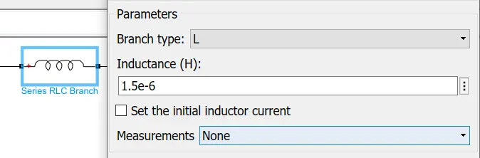
3) Now, we will choose a an inductor for 40% current ripple:
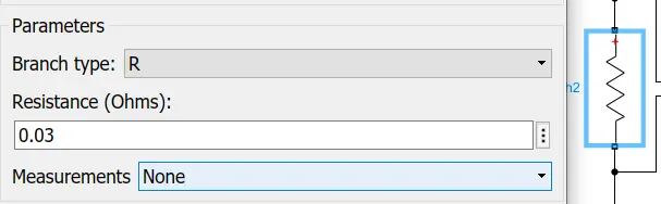
R=Vout2P=0.03">R=V2outP=0.03R=Vout2P=0.03
IL=VoR=100A">IL=VoR=100AIL=VoR=100A
L=VoutFs⋅ΔIl⋅(1-D)">L=VoutFs⋅ΔIl⋅(1−D)L=VoutFs⋅ΔIl⋅(1-D)
L=1.5e-6">L=1.5e−6L=1.5e-6
4) Now we are calculate the Cpacitor:
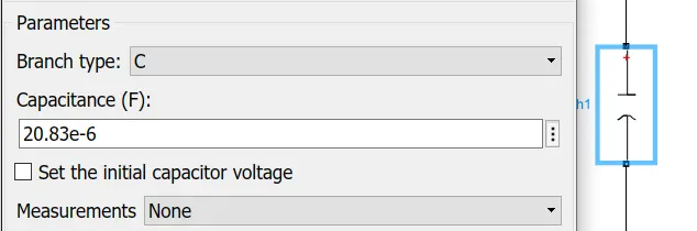
C=1-D8L⋅FS2(ΔVOVo)">C=1−D8L⋅FS2(ΔVOVo)C=1-D8L⋅FS2(ΔVOVo)
C=20.83e-6">C=20.83e−6C=20.83e-6
From all the above All calculation we are model now the interleaving DC/DC converter:
The recent development of battery-powered applications is improving the need of efficient step-up dc-dc converters. Nowadays, step up conversion is widely used in many applications like Electric vehicles, Photovoltaic (PV) systems, Uninterruptible power supplies (UPS), and fuel cell systems. By paralleling the converters, the input current can be shared among inductors so that high reliability and efficiency in power electronic systems can be obtained. In this paper, the conventional boost dc-dc converter and interleaved boost dc-dc converter are simulated using MATLAB/SIMULINK and MULTISIM software. The converters are tested by varying the input voltage with a constant duty cycle in Continuous Conduction Mode (CCM). The performance parameters of the converters are compared. The converters are controlled by interleaved switching signals, which have the same switching frequency but the shift in phase. Using interleaved converter we can get improved efficiency, reduced ripple voltage, reduced inductor current ripple, fast switching speed.
As for high efficiency we used multiphase system to increase the efficiency
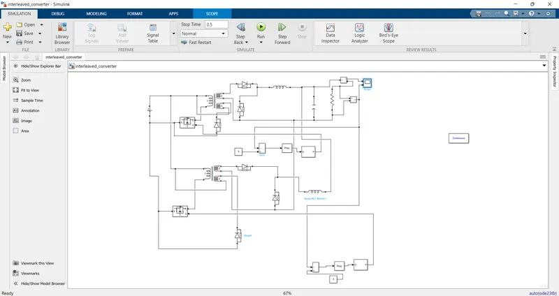
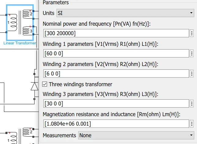
In this model, we are using the following parameters which we calculated:
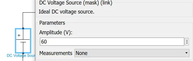
1) Input Voltage:
2) Transformer Capacity:
3) Inductor value:
Capacitor:
Output Load:
Gate pulse:
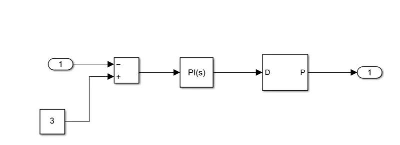
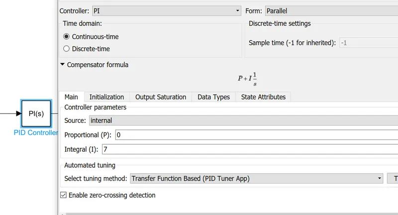
As we required the 3V so we were given the reference as the Constant 3 and PID get the tunned so PID value are as follows:
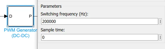
The frequency is chosen is 20000hz :
Now we run the model for 0.5 sec and get all outputs :
Output voltage:
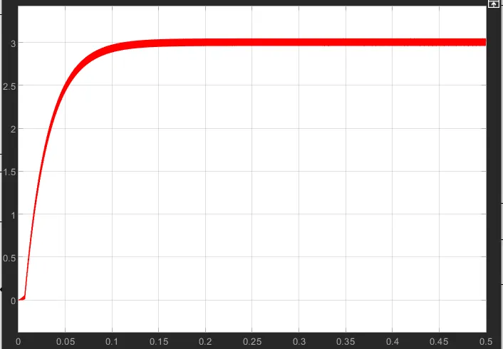
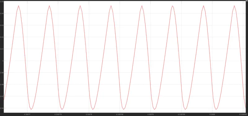
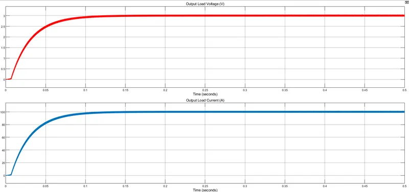
As we output voltage is getting 3 Volt same as we required with some ripples and ripple also same as we calculated which is shown in the following graph.
The ripple of output Voltage:
Output Current:
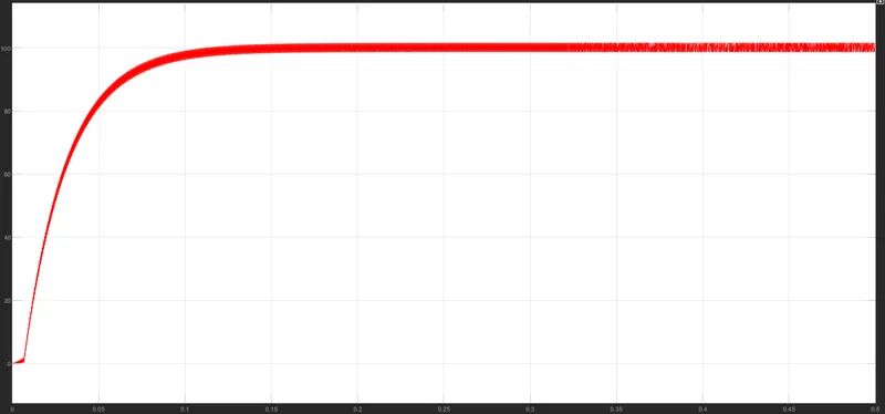
Current is 100A this is because of the isolated system and multiphase system getting the perfect as same as requirements.
Output Voltage and current:
Input Voltage:
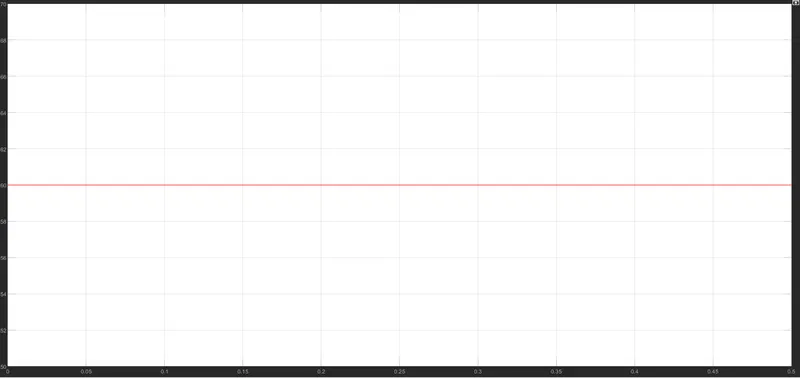
As our input voltage is 60V given to the converter.
Input current:
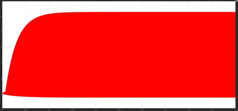
Because of switching action of MOSFET input current is looking like this if zoom it, it will look like step voltage which is shown in the following graph
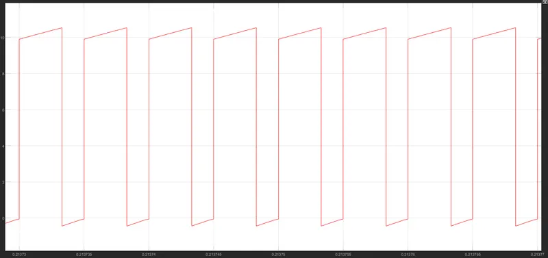
The current amplitude is max is 10 volt and the minimum voltage is near to zero so as calculate the average value then ware getting the 4.7A approximately.
Inductor Voltage:
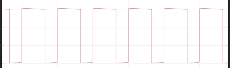
VOltage is as plus and magnitude are 2V and -4 V.
1)The main aim is to get efficiency as higher as possible and as you see in our requirement are getting approximately same.
so we can say that our efficiency is above / more than 90%.
1) As efficiency is calculated from output power/ input power so as we calculated for this converter as following:
Input voltage = 60V
Input current = 5A
Output Voltage = 3V
Output Current = 100A
from all the above data, we get the Input power is 300W and output Power is also 300W
so our efficiency is 100% without considering the ripple in voltage and current, if we consider the ripple also we can get the eifficiency more than 90%.
B.
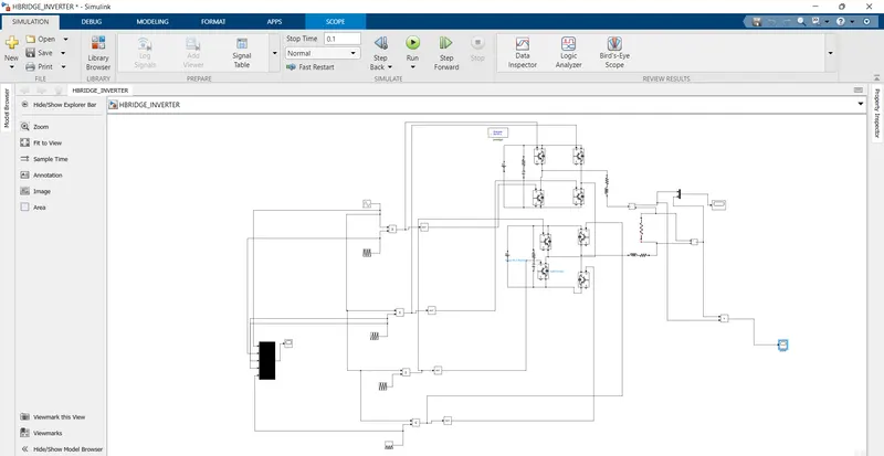
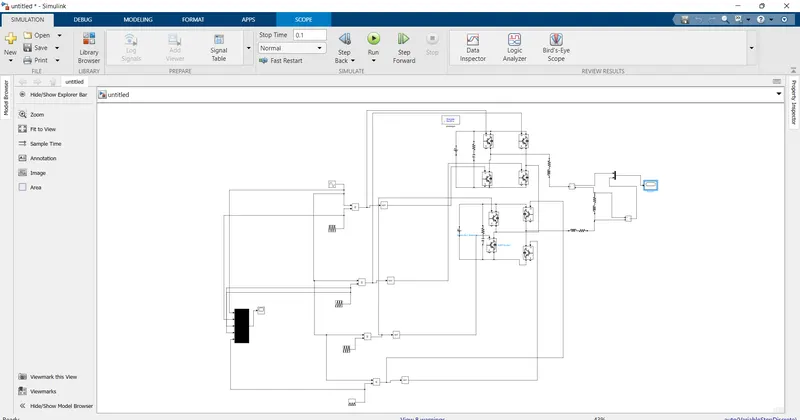
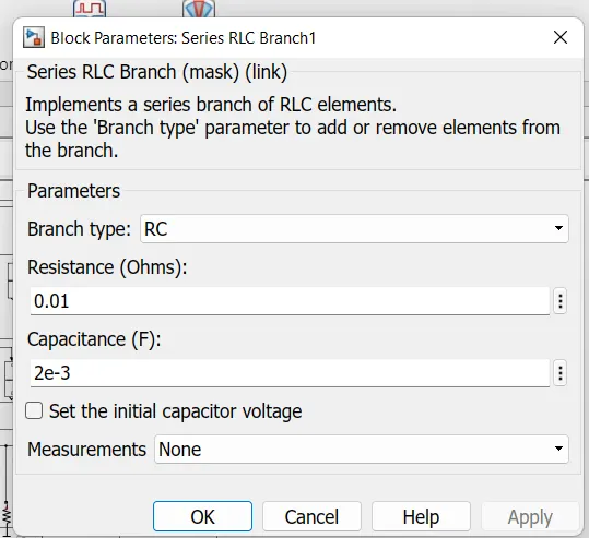
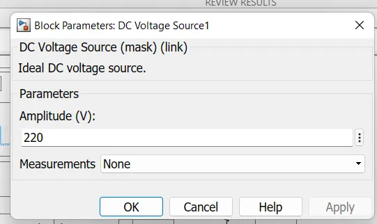
2. Two DC/AC H-bridge inverters are connected to a point of common coupling of a micro-grid system. The inverters are fed from voltage sources and are importing power to the micro-grid, to feed an AC load of 5 kW & 2 kVAR. The micro-grid AC voltage amplitude is set at 170 V, while the micro-grid operating frequency is 60 Hz. The DC sources (V_s1 and V_s2 ) operate at a DC voltage of 220 V. Inverters 1 and 2 have capacities of 4 kVA & 3 kVA respectively. While C_1 &〖 C〗_2 are sized at 2 mF. R_1,L_1,R_2 & L_2 represent the line impedance and can be ignored in this problem.
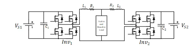
Figure 1. Micro-grid System for two parallel inverters.
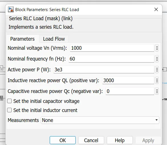
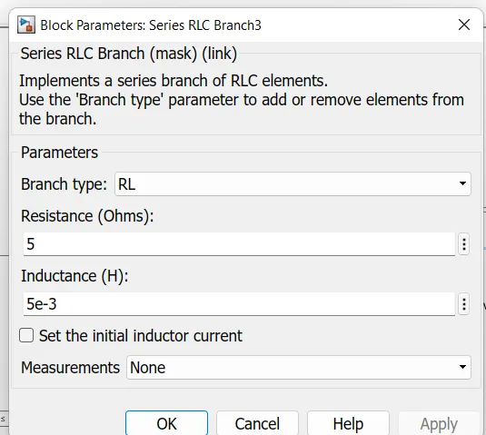
- What are the values of the passive components (R, L and⁄or C) that you can use to model the active and reactive loads?
- Design the droop control parameters of the inverters to ensure that the micro-grid operating voltage and frequency are within 0.5% of their respective nominal values at the aforementioned load conditions.
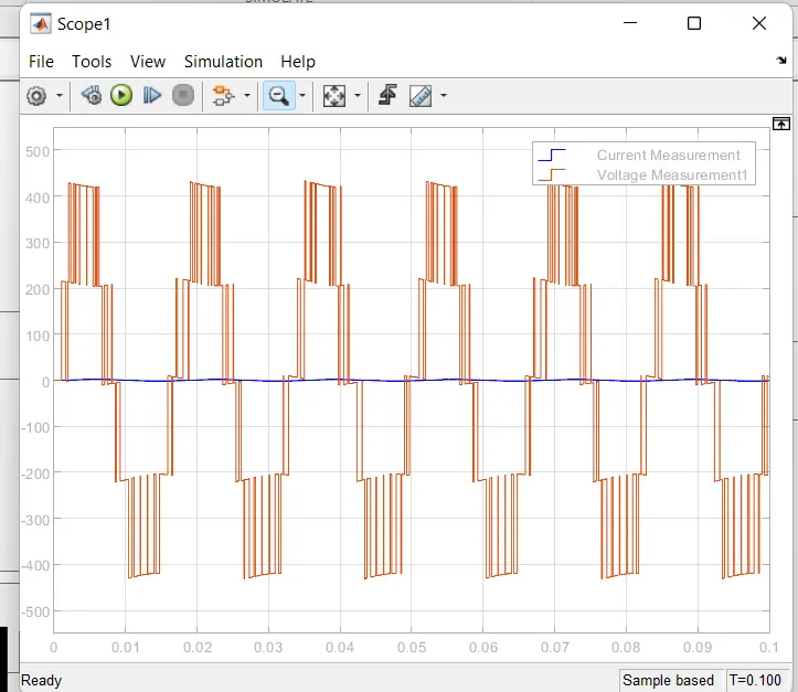
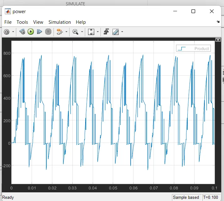
- Simulate the circuit and show complete results including the delivered load active and reactive power, the micro-grid operating frequency & voltage, the active and reactive power sharing of every inverter, etc.…
- Apply a sudden change in the active power load by dropping it 3 kW after it reaches steady-state and verify that the power-sharing between the two inverters is maintained.
- Show the simulation plots for the above case and comment on it.
- Apply a sudden change in the reactive power load by increasing it to 3 kVAR after it reaches steady-state and verify that the power-sharing between the two inverters is maintained.
- Show the simulation plots for the above case and comment on it.
ANSWER:
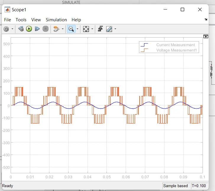
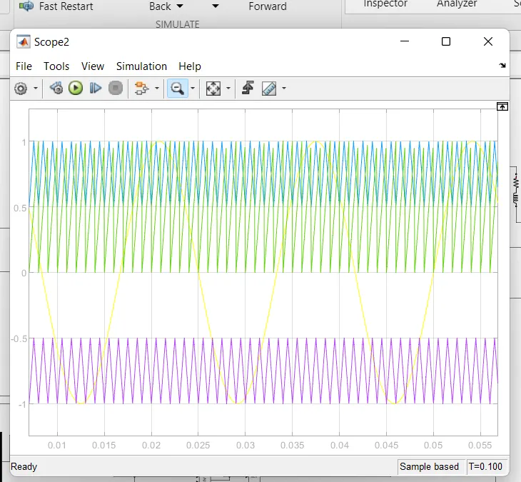
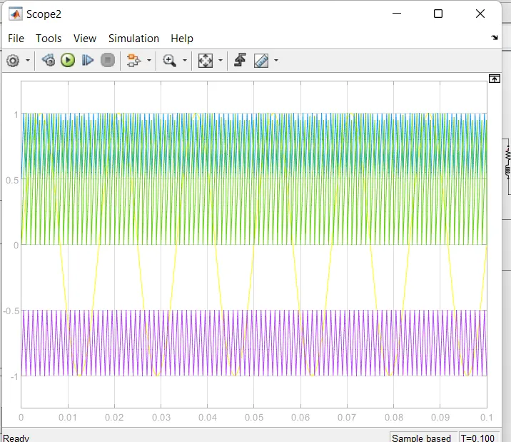
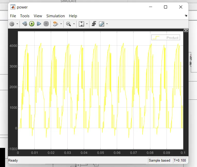
- Apply a sudden change in the reactive power load by increasing it to 3 kVAR after it reaches steady-state and verify that the power-sharing between the two inverters is maintained.
load: