Meshing of Spare Tire Well using HyperMesh
Aim:
The main aim is to extract the mid surface, mesh the component, and give the thickness to the given component.
Methodology:
The methodology for the given model is as follows.
- Opening the File.
- Performing the Geometry Clean up
- Extracting the Mid Surface.
- Giving the Quality Criteria.
- Generating the Mesh.
- Clearing the Errors.
- Giving the Thickness (Automatic).
Theory:
Spare Tire Well:
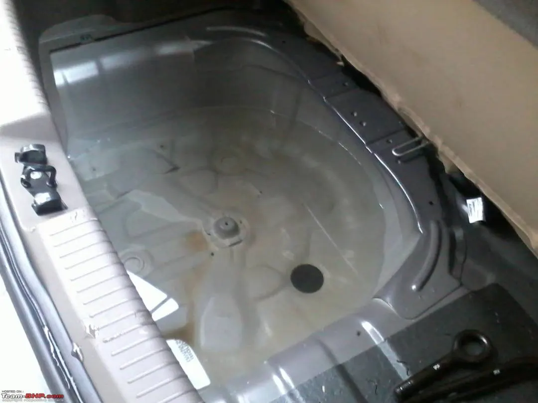
A Spare Tire Well is a recessed area in a car-truck where the spare tire is placed without affecting the Boot space. In Most of the Cars the Spare tire well, the storage space for the Spare tire, jack, and Lug wrench is given. Previously, they were made of steel but recently due to the advancement of technology, aluminum is used. The looks of the Spare tire well is tube-like component. Recently, a Big Company used a glass pelletized Thermoplastics for the Spare tire Well in one of its sedan car and is expected to represent a new level of functional integration and weight reduction in this application. It is said that the structure is a hybrid.
Switching from metals to composites for this type of component does benefit the automakers and the consumers. If the Spare Tire Well component is changed from metal to composite, the Weight is reduced which in turn increases the fuel economy. The composite generally cost 10-15 percent less than the normal metal cost (general survey).
Procedure:
- Opening the File:
- The File given is a ‘.hm’ File. It can be opened directly by following the steps.
- In the Main Bar, Select File >> Click Open >> Click Model>> Select the File to open >> Click Open.
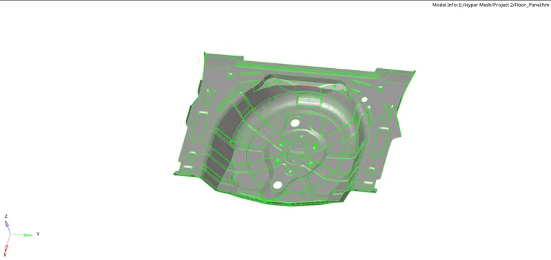
- The file is opened. To view the Model (if the Screen is empty), Click ‘f’ on the keyboard to fit the model on the screen.
- Performing the Geometry Clean up:
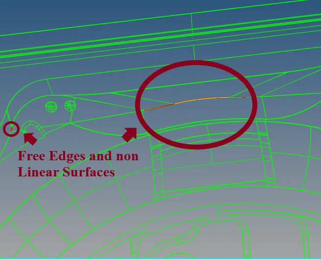
- The Initial model has some CAD errors which need to be fixed manually so that the mid surface extraction will be smooth.
- The CAD errors can be changed using the Quick edit tools.
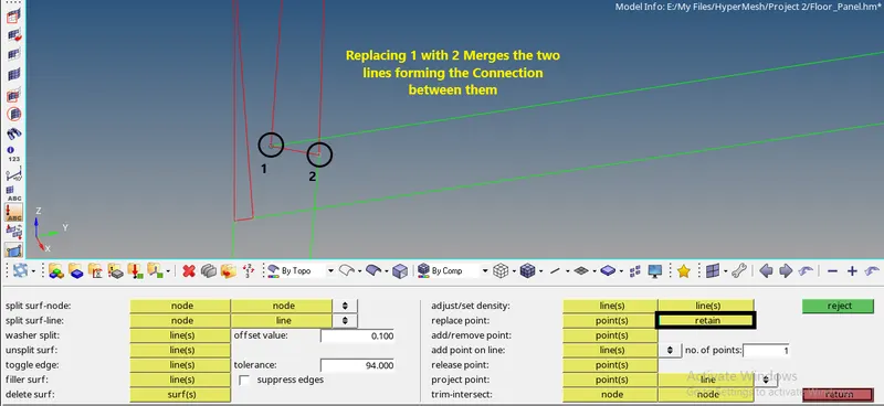
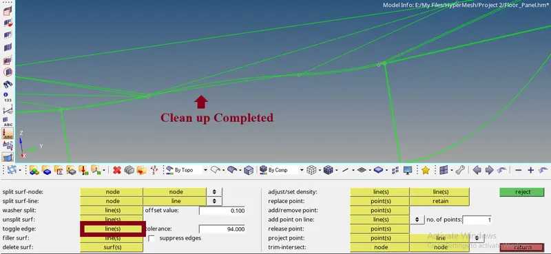
- If the CAD is coming out the shape showing the free edge ( can be seen as the red line ) then the points attaching to it can be released and then again toggling the line makes it double cons and hence, making a connection between them.
- If the Shape is disturbed badly then the surface should be deleted and the changes should be done and then create a new surface using the Ruled option in surfaces Panel or just clicking the Fillet surfaces in quick Edit Panel (Note: Fillet Surfaces only works for the Closed loops).


- Extracting the Mid Surface:
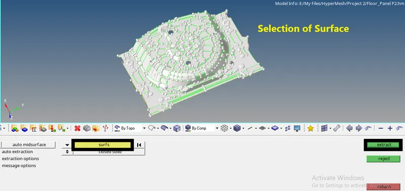
- To Extract the Mid Surface, the Auto mid surface option is used as the model has an almost uniform thickness.
- For Auto mid surface, Go to the mid surface panel in the Geom Tab >> Select the Surface >> Click extract.


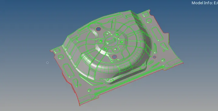
- The Midsurface is created.
- Giving the Quality Criteria:
- The Quality Criteria is an important task which is to be used to get the required outcome of the mesh.
- This helps to retrieve the mesh with the given criteria. To give the criteria,
- Go to the Preferences tab in the Main Menu >> Click Criteria file settings >> Give the values as given >> Click Apply. >> Click Ok.
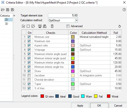
- The Quality Criteria are given.
- Generating the Mesh:
- To mesh the model, either the whole model is selected at a time or a part of the model is selected separately.
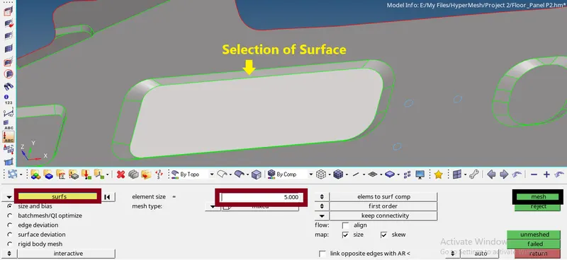
- Go to the 2D window, Click auto mesh >> Select the surface to mesh >> Give the Element size >> Keep the mesh type as mixed >> Click mesh.

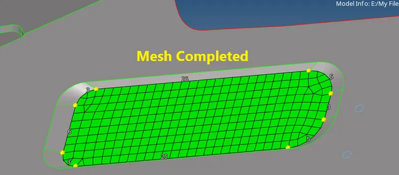
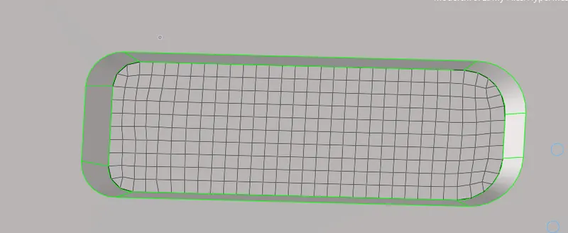
- The mesh is created.
- If the mesh flow is not good, select the down arrow beside surfs to change it to elements >> select the elements to remesh >> click mesh the software gives the optimal mesh.
- Clearing the Errors:
- The errors occur when the elements fail to meet the given quality criteria.
- To clear the quality criteria, Go to the 2D panel, Select quality Index >> Click cleanup tools >> Select the tools you want to use to clear the Errors.


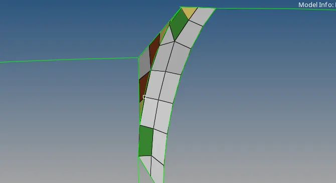
- The errors will be cleared.
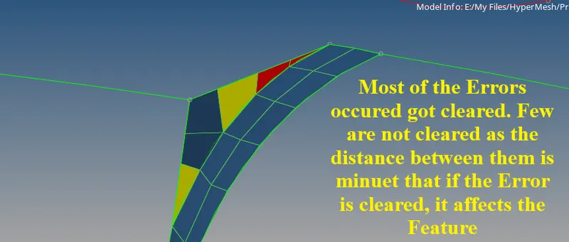
- Feature Capturing is an important aspect while performing any FEA operation. Sometimes, the given Model may fail to capture the feature. Sometimes a compromise must be done to complete the task that is either to go with the feature capturing or to go with the clearing of errors without bothering about the Feature. But the usage of either should be done wisely to get a better result. If not the model may not be suitable for analysis.
- Adding the Automatic Thickness:
- The Automatic Thickness gives an auto-calculated thickness by using an algorithm in the software itself, by calculating the surface distance and the FE Elements.
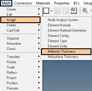
- To add the automatic thickness, Go to the Mesh bar in the Main Menu >> Click Assign >> Click Mid Mesh Thickness. >> Select input from Entities >> In Solid Geom/mesh, Change from Solids to surface >>Select the Surface >> In Mid Mesh, Select Elements >> Select the Elements to Generate the Mid Surface >> Check the Minimum and Maximum thickness boxes >> Give the Minimum and Maximum thickness (Note: Maximum can be left as is but the minimum should be less, preferably 0.1, so that the thickness range will be better.) >> Check the 3D Element Representation box >> Click on Calculate thickness.
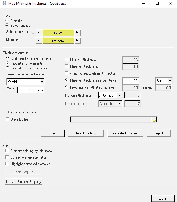
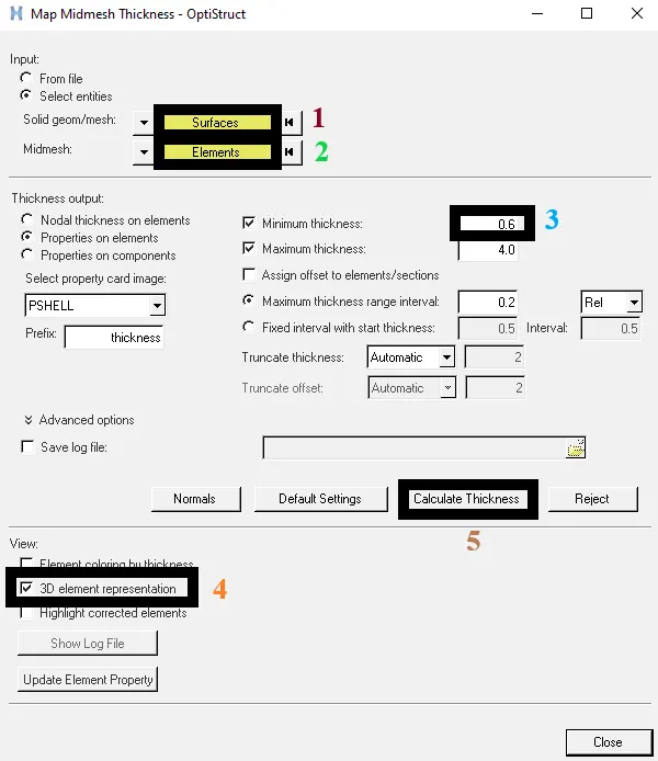
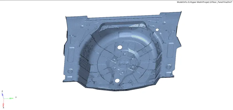
- The Thickness is assigned and the properties are automatically created with the thickness number.
- This is an easy way to give the thickness to the component.
Tools Used:
Mid Mesh Thickness:
The Mid Mesh thickness is the thickness that is assigned to the mid mesh either on node card, element card, nodal thickness on element card, or as properties on elements or components. The assigning and calculating the thickness is done inside the HyperMesh. The Property assigning is calculated based on the inputs given.
Result:
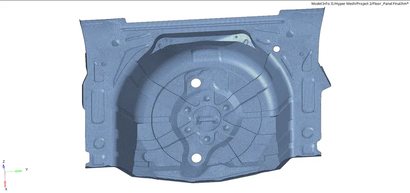
The mid surface is extracted properly and the Mesh is generated properly along with the thickness assignment.
Final Meshed Component:
Final Meshed Component Showing Errors:
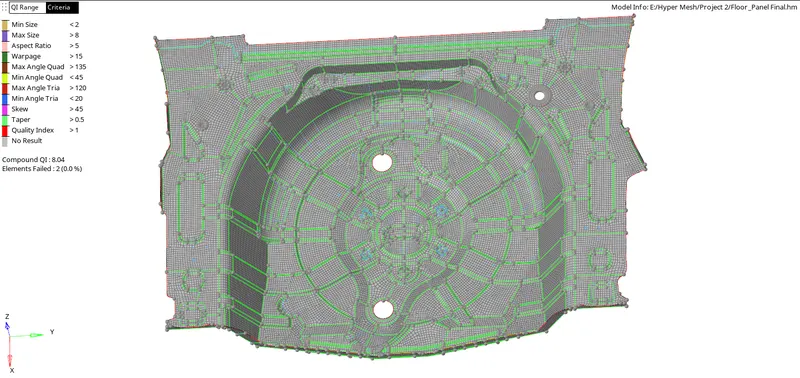
- The image above shows that there are 2 errors remaining. The Errors are kept as is to maintain the feature as disturbing the Feature affects the simulation.
Final Meshed Component with Auto Assigned Thickness:
Learning Outcomes:
The Learning outcomes are not that much in this project but honing the skills learned helped to complete the task effectively.
- Learned to use automatic Thickness assigning tool.
Links: