Project 2
*Project 1 is the choice of simulation.
-Expectation.
Design an interleaving DC/DC converter system for a data centre application with the following specifications:
• Input voltage: 45 – 60 v
• Output voltage: 3 V
• Output current: 100A
• Efficiency > 85%
Simulate the system using a Spice-based software simulation tool such as LT-Spice, Pspice, PowerSim, TINA, etc...
Show your design in details (most probably, you will need to use an isolated system to achieve this low voltage conversion ratio, you might also need to use a multiphase system to increase the efficiency).
Show the input voltage, the output voltage, the input current, the output current, the system efficiency and any other simulation plots necessary to evaluate your design.
Calculations
*The system will be simualted using matlab simulink.
-Input values for this simulations are
Vin = 45-60V
vout = 3V
output current = 100A
P = 300W
fs = 100KHz
-To achieve this low rate of voltage level convertion, an isolated system with help of a transformer will be needed.
-Before going into the calculations some certin absumtions will be made. first the convertion ratio of both transformer windings are 1:15 mean N1 = 10 and N2 = 150.
-The following formular is used to calculate the Duty cycle of the circuit
`(Vout)/(Vi n) = (D)/(1-D)*(N1)/(N2)`
Vout=3V
Vin = 55V
N1 = 10
N2 = 150
Subytituting and looking for D.
from here we see that
D = `(450)/(1000)`
This gives us a value of 0.45 for duty cycle.
R = 3V/100A = 0.03 ohms
Lmin = `((1-D)^2 * R)/(2*fs)*(N1)/(N2)`
This gives us a minimum magnetising inductance of 18.5uH but a grater inductance cooled still be used.
Cout = `D/(R*fs*((triangleVout)/(Vout)))`
This gives a capacitance of 300uF.
Simulation
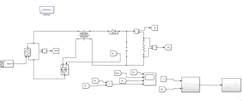
The circuit is set up as shown above with a feedback for voltage control. all above values are entered (R,C,L) the reullts is as shown below.
Results:
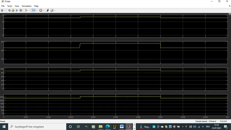
-the first plot is that of the output voltage which is somewhre below 3V.
-The second plots shows the input voltage which varreis between 50 and 60V
-The thrid plot is that of the output current which close to a 100A
-The third plot shows the reulsting output power which is just a multiplication of output volatge and current.