Project 2
Aim:
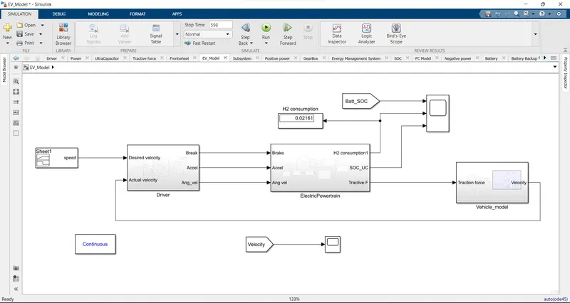
To design the complete working model of Hybrid Fuel cell Electric Vehicle with battery and Ultracapacitor and to analyze fuel consumed, current, Load sharing and state of charge of battery and ultracapacitor.
Blocks used:
- Repeating sequence
- Memory
- Integrator
- Derivative
- Add
- Subtract
- Product
- Divide
- Abs
- Square
- Square root
- Greater than
- Constant
- Switch
- Saturation
- Gain
- Goto
- From
- To workspace
- Max
- Min
- OR
- AND
- In
- Out
- 1-D lookup table
- 2-D lookup table
- Reciprocal
- Interval test
- Zero order Hold
- Transfer function
- Stop
Driver Subsystem:
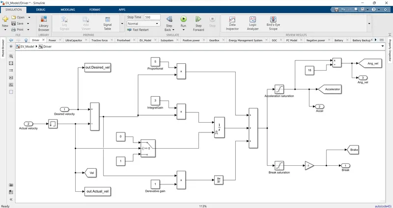
- This input desired velocity is given to driver subsystem to produce accelerator and brake command by comparing with the feedback actual velocity.
- These accelerator and brake command are then converted to the tractive force through sequential calculation in the electric powertrain subsystem.
- Then the tractive force is given to the vehicle dynamics subsystem to convert it to actual velocity of vehicle.
- Input to this system is desired velocity and actual velocity.
- Driver subsystem is actually a PID controller.
- Error signal is calculated by comparing the desired and actual velocity.
- This error signal is then is then fed to proportional, integral and derivative controller.
Electric Powertrain subsystem:
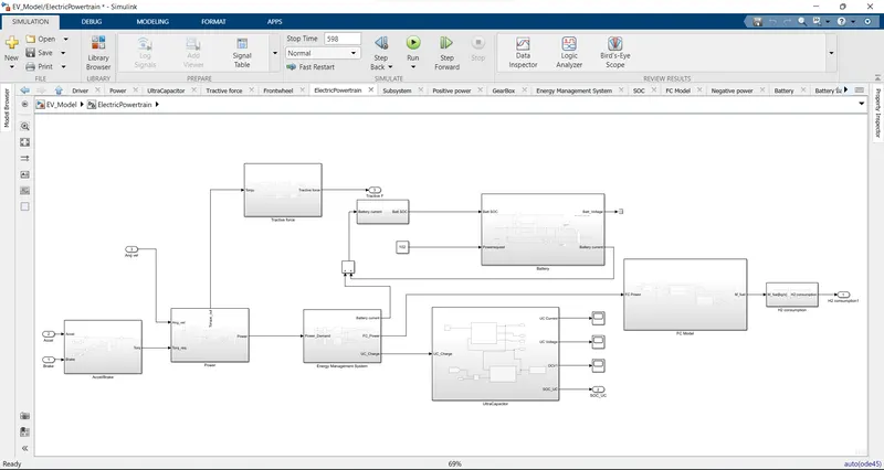
- Input to the subsystem is accelerator and brake commands.
- This consists of controller, torque/power, tractive force, Energy management system, fuel cell system, H2 consumption and energy storage system.
- The output of the subsystem is tractive force, hydrogen consumption, SOC of battery and ultracapacitor.
Accel/Brake:
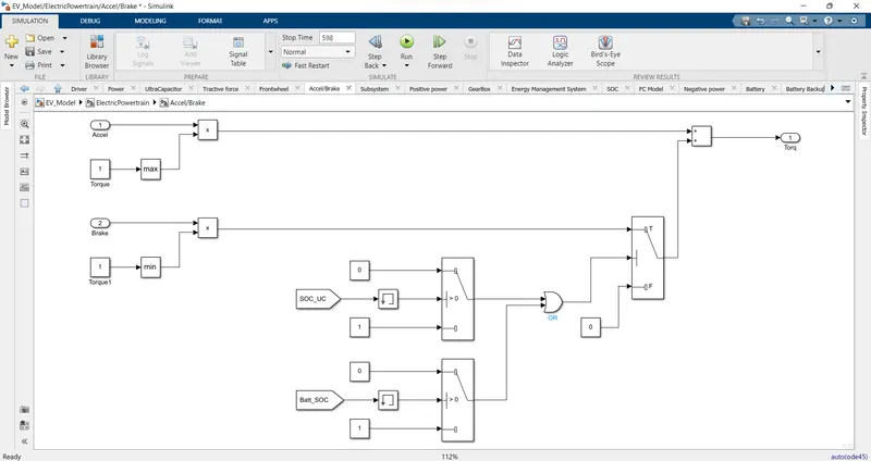
- The input of the subsystem is accelerator and brake command and the output is torque request.
- The accelerator command is multiplied with the maximum torque value of the electrical machine to produce the Positive torque request.
- The brake command is multiplied with minimum torque value of the electrical machine to produce negative torque request.
- And the negative torque is requested if the any one of state of charge of ultracapacitor and battery is greater than 0.8.
- If the SOC of Battery and ultracapacitor is less than 0.8 then the negative torque request is 0 goes for regenerative braking.
- Both positive and negative torque request is added to get the total torque request.
Power subsystem:
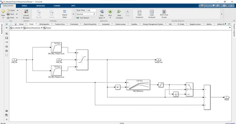
- The input of this subsystem is torque request and output is Torque out and power demand.
- According to the Electrical machine angular velocity, the maximum and minimum torque is set by using lookup table (Max torque curve and Min torque curve) and if the torque request is within this limit, then the torque is given as output.
- The power is calculated from the Torque and angular velocity.
P = T*w
Energy management subsystem:
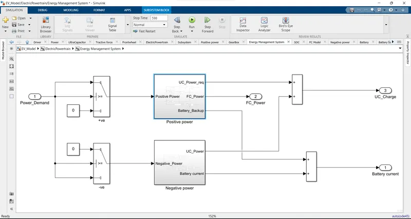
- Energy management system is used for load sharing among the energy devices to efficiently operate the vehicle by operating in the optimum region of Battery, ultracapacitor and fuel cell.
- The input to the subsystem is Power demand.
- The output is Fuel cell power, ultracapacitor power and Battery power.
- If the power demand is positive, that is used for propulsion.
- If the power demand is negative, that is used for regeneration.
- The load demand sharing algorithm has to be used to deliver the load.
Possitive power subsystem:
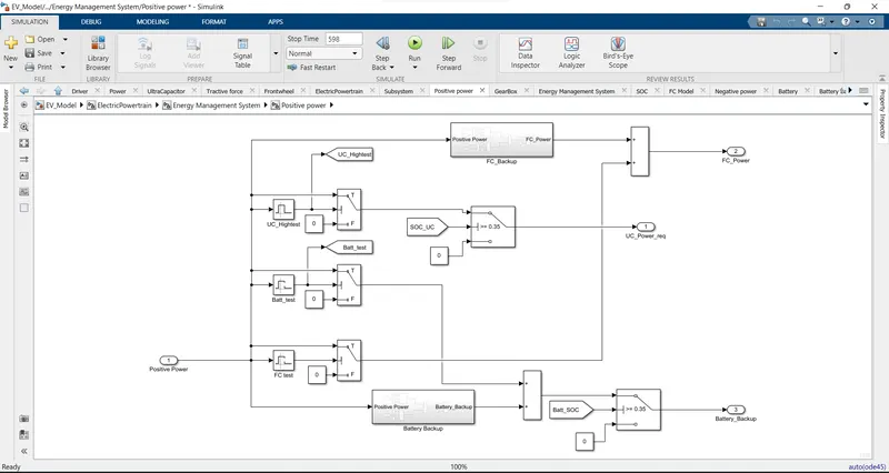
- The operating range for the fuel cell is 23kW to 55kW. It is derived from the polarization curve. This power is delivered by fuel cell.
- If the power demand is low i.e., in our case if it is less than 23kW and if SOC is greater than minimum value of battery then this power has to be delivered by battery.
- If the power demand is high i.e., in our case if it is more than 55kW and if SOC is greater than minimum value of ultracapacitor then this power has to be delivered by ultracapacitor.
Fuel cell backup system:
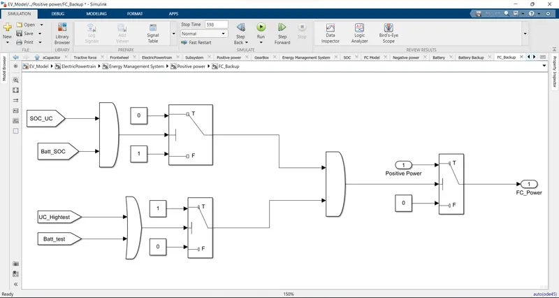
- If the power demand is above 55kW and if SOC of ultracapacitor is greater than minimum value then this power has to be delivered by ultracapacitor.
- If the SOC of Ultracapacitor is less than minimum value, then this power has to be met by battery.
- And if both SOC of battery and ultracapacitor is less than the minimum value then that power has to delivered by fuel cell.
Battery backup subsystem:
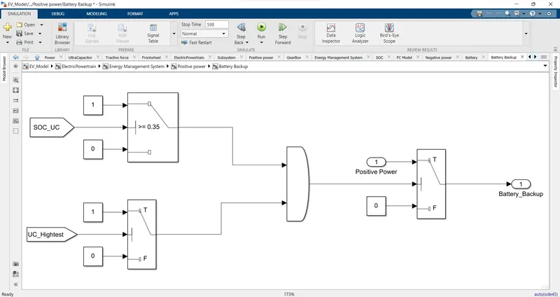
- If the power demand is high i.e., in our case if it is greater than 55kW and if SOC is less than minimum value of ultracapacitor and if the SOC of battery is greater than minimum value then this power has to be delivered by battery.
Negative power subsystem:
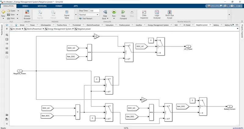
- For the negative power i.e., regenerative braking, if the SOC of ultracapacitor is greater than battery then the regenerative power is used to charge the battery.
- If the SOC of ultracapacitor and battery is equal then 0.5C charging is done for both ultracapacitor and battery.
- If the SOC of Battery is greater than ultracapacitor then the negative power is used to charge the ultracapacitor as the same way as battery.
- The Ultracapacitor power from the positive and negative power subsystem are added to get the total Ultracapacitor power.
- The battery power from the positive and negative power subsystem and the battery backup power are added to get total Battery power.
- The Fuel cell power and fuel cell backup power is added to get total fuel cell power.
Fuel cell subsystem:
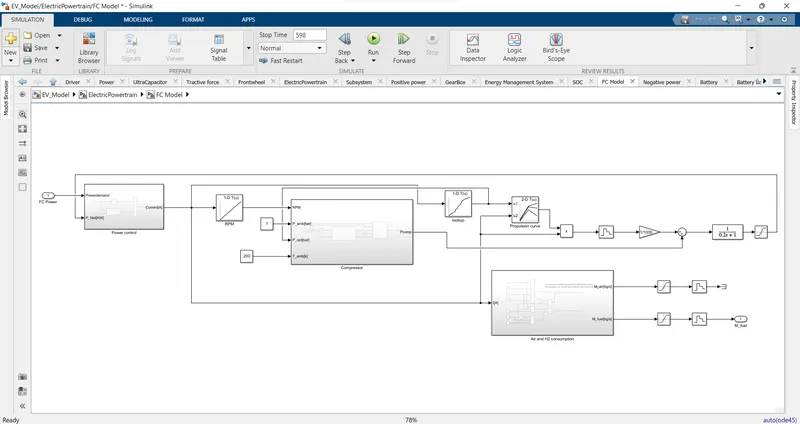
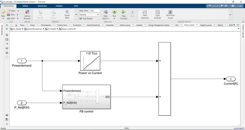
- According to power demand, the current is obtained from the Power-Current curve.
- This is then added with the controller output.
- The controller is PID controller which process the error signal and gives current as output.
Power subsystem:
PPID control:
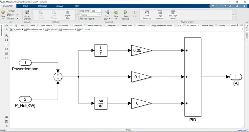
- According to power demand, the current is obtained from the Power-Current curve.
- This is then added with the controller output.
- The controller is PID controller which process the error signal and gives current as output.
Compressor subsystem:
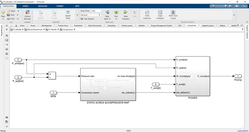
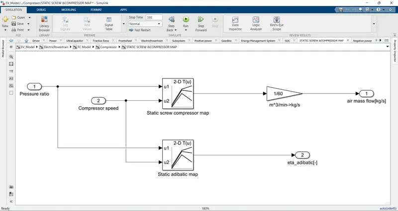
- The compressor is used in cathode side to maintain the optimum pressure for the oxygen from air to enter in the fuel cell for the proper working and efficiency.
- The input to the subsystem is the ambient pressure and optimum pressure from the lookup table.
- From this pressure ratio and compressor speed, the airflow is obtained and is converted to kg/s from static compressor map and the eta adiabatic is obtained from the static adiabatic map.
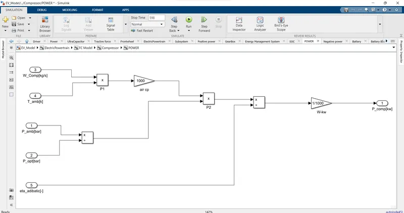
- The input to the power calculation for compressor subsystem is air mass flow, ambient temperature, ambient pressure, eta adiabatic and optimum pressure.
- The output of the subsystem is compressor power.
Air and H2 consumption system:
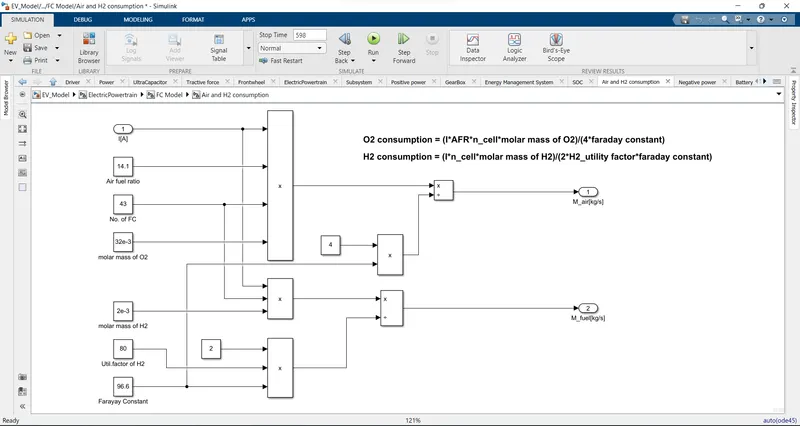
- The input to this subsystem is current and other parameters inputs are air fuel ratio, number of cells, molar mass of oxygen, molar mass of hydrogen, hydrogen utilization factor and faraday constant.
- From current obtained from the fuel cell, oxygen and hydrogen consumption is obtained by using the formulas.
Oxygen consumption = ( I * AFR * n_cell * molar mass of O2)/( 4 * faraday constant)
Hydrogen consumption (kg/s) = (I * n_cell * molar mass of H2)/(2 * H2_utility factor * faraday constant)
Hydrogen consumption subsystem:
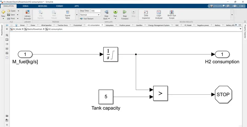
- The input to the system is hydrogen consumption in kg/s.
- It is then integrated to get the total hydrogen consumption inn kg.
- If the total hydrogen consumption is greater than the tank capacity of the hydrogen the simulation has to be stopped.
Battery subsystem:
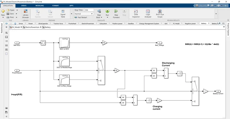
- The energy storage system consists of ultracapacitor and battery.
- The input of the subsystem is ultracapacitor power and battery power.
- The output is state of charge of Ultracapacitor and Battery power.
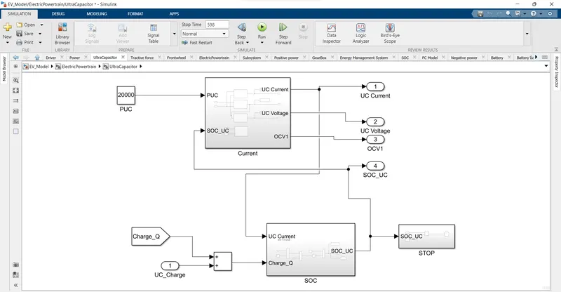
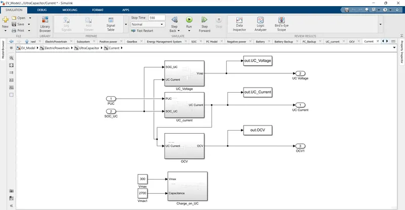
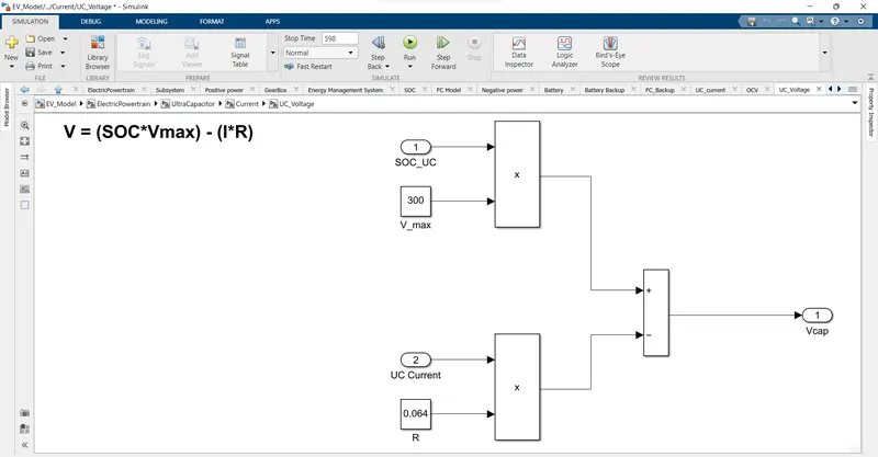
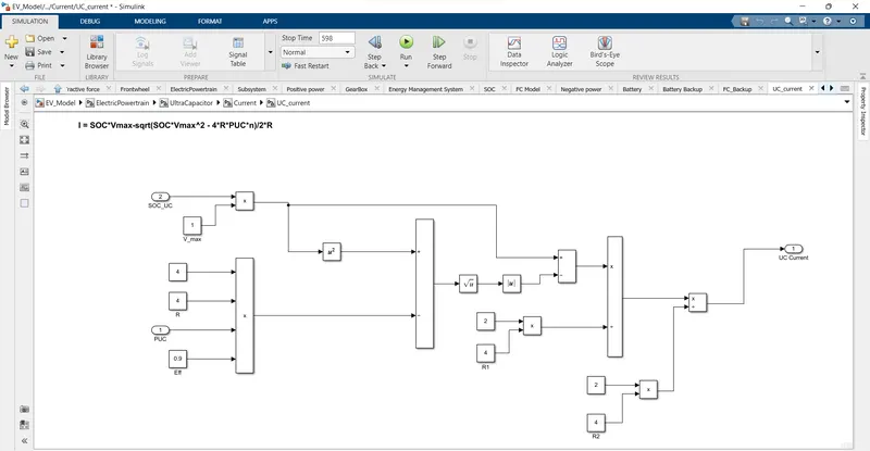
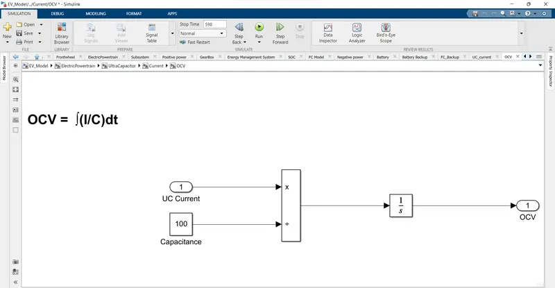
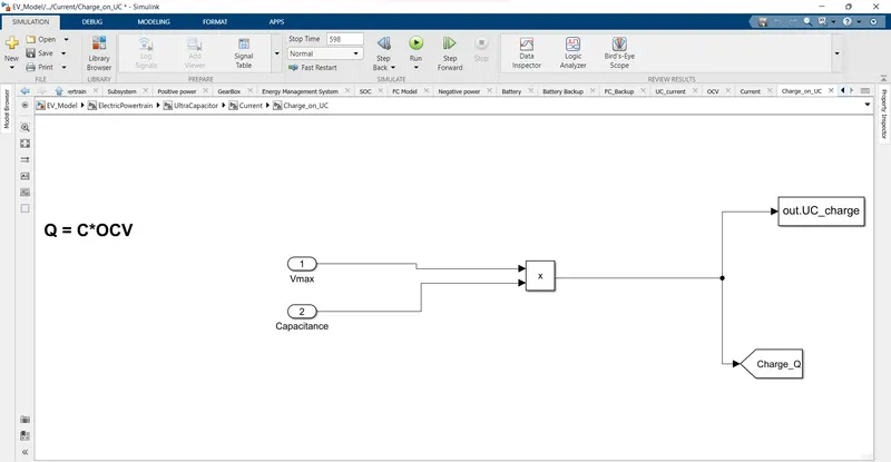
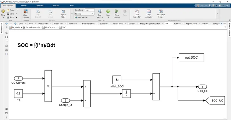
- In the charge and voltage calculation subsystem, the current, voltage, open circuit voltage and charge calculation subsystem is formed.
- The current calculation is done by using the formula,
I = ((SOC*V_max)-sqrt((SOC*V_max)^2-(4*R*P_uc*eff))/(2*R)
Tractive force:
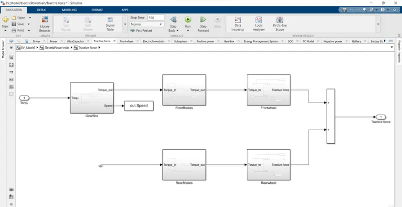
- The input to this subsystem is Torque.
- The torque is converted to force and is given as output.
- This subsystem consists of Front brakes, front wheels, rear brakes and real rear wheels subsystems.
Gear Box:
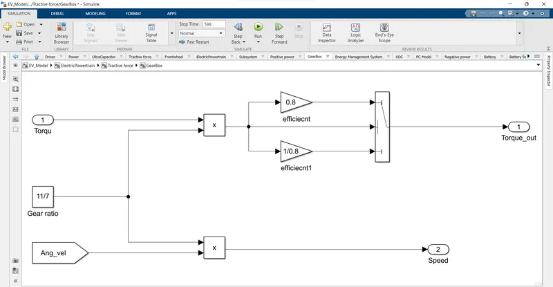
- The torque from the electrical machine is multiplied with gearbox ratio and gearbox efficiency to get the torque.
- The Angular vehicle velocity is then multiplied with gearbox ratio to get EM speed.
Front Brakes:
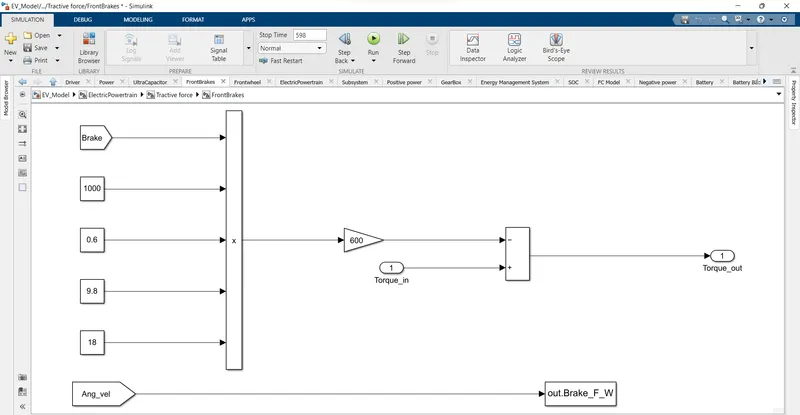
- Vehicle brake torque value is added to the input torque to get the Output torque.
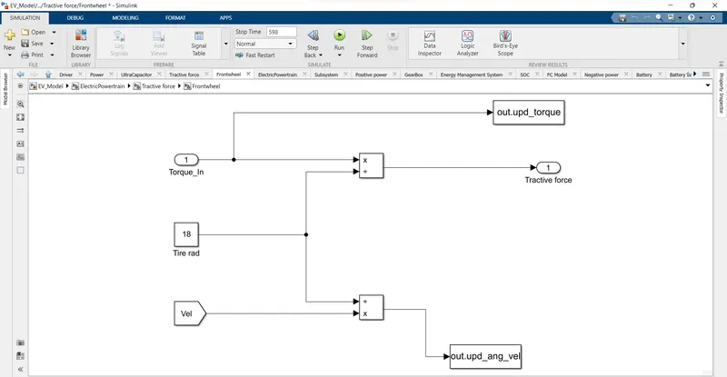
Front Wheels:
- The tractive force is calculated by dividing the vehicle tire radius from the torque value from the Front brakes.
- This force is used to drive the vehicle.
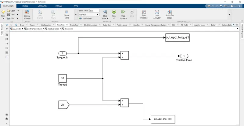
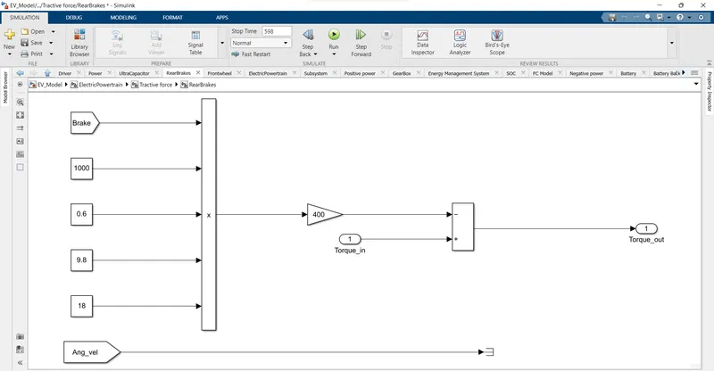
- Rear brake subsystem is similar to the front brake but the only difference is input torque is grounded because we consider Front wheel drive only.
Rear wheel:
Rear Brake:
Vehicle Dynamic model:
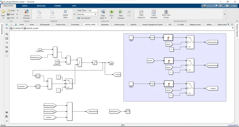
- The input to this subsystem tractive force which is converted to velocity and is given as output.
- The Opposing force is reduced from the input tractive force and acceleration is calculated by dividing with vehicle mass.
F = m*a.
- The acceleration is then integrated to get the actual velocity of vehicle.
- But due to the integral windup the overshoot occurs.
- This occurs because initially the error between the actual and desired velocity is more. In order to overcome this error, the overshoot occurs.
- Then due to this overshoot, another fluctuation less than desired velocity to overcome the error due to overshoot.
- This windup can be overcome by using anti windup. This is obtained by using external reset.
- When the acceleration and velocity is not equal to zero, then external reset is set.
- When the acceleration and velocity is zero, then the external reset is reset.
- By considering the initial condition of vehicle which is zero, in order to reject the unwanted errors, the memory is used.
Result:
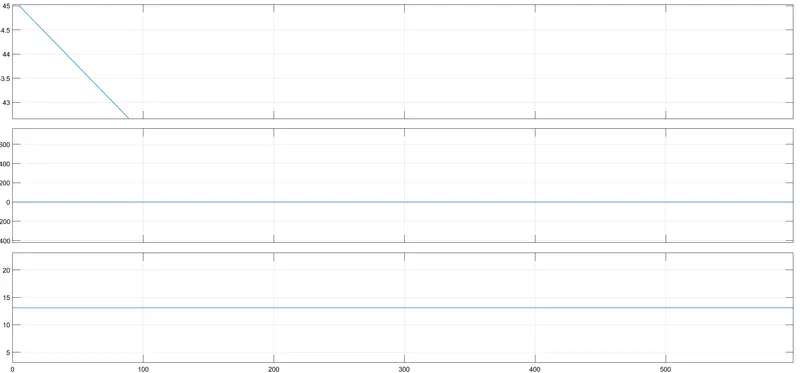
UC_Current:
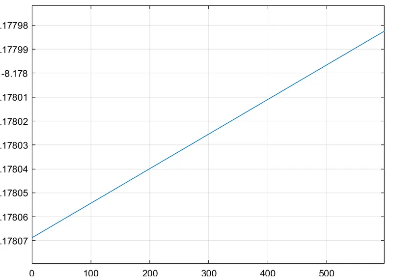
UC_Voltage:
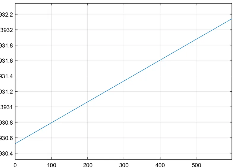
OCV: