Week - 4
Q1.
The image below shows the condition when the powersupply is not given to the system i.e 0.
Theere are two inputs that we have given to the syste namely Powersupply and Watersupply.
Below that are lamps for it.
The outputs for flow chart are rinsing having data point as c, dryer having data point d, watersupp(watersupply) as w, soaking as a, washing as b, over as e, powersupp(powersupply) as p.
There are lamps indicating the conditions for powersupply, watersupply and over.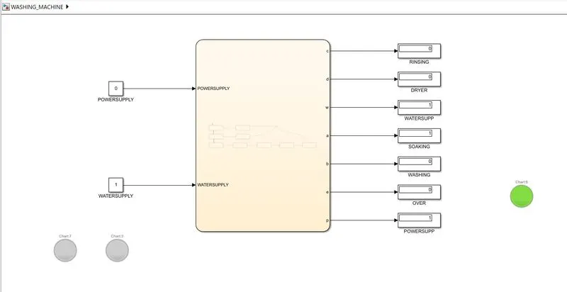
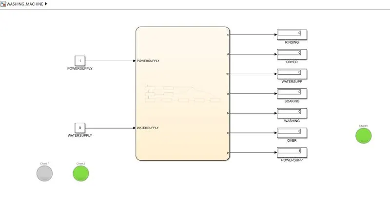
The below diagram shows the condition when the powersupply is given but watersupply is not given.
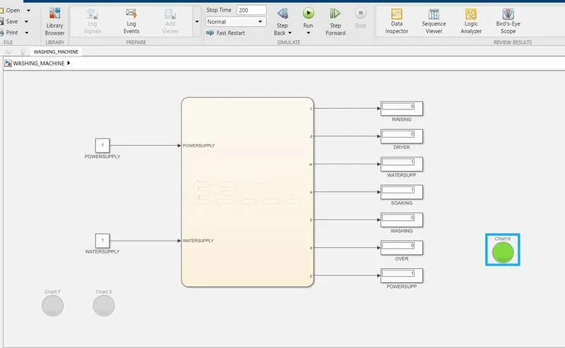
After first 200sec's the condition shows that soaking is done when both power supply and watersupplies are available.
After 300sec's machine stays in ON condition for 100 sec's i.e washing process is compleated at 300th sec.
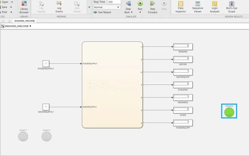
After 300 sec's rinsing starts and goes on for 20 sec's at normal condition. Thus the watersupply also wont be available.
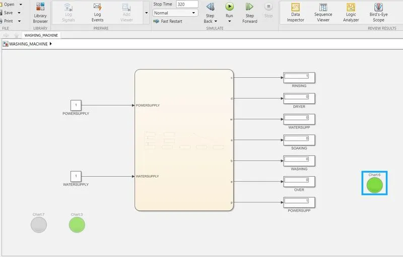
When rinsing is done dryer starts for 50sec's.
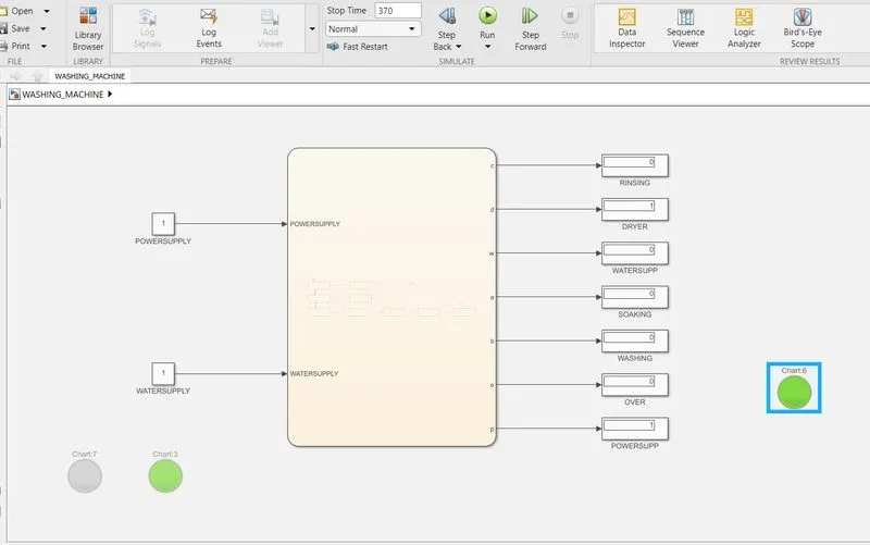
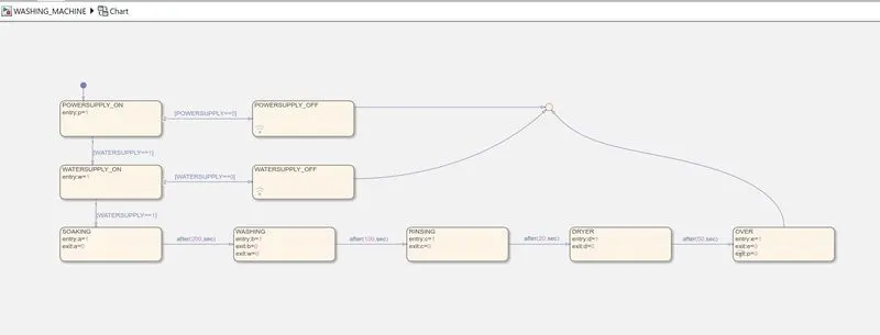
Below shown is the flow chart logic for the system.
The logic states the following conditions:
1. The powersupply is denoted by variable p. It means it is ON when p=1 and OFF when p=0.
2. The watersupply is denoted by variable w. It means it is ON when w=1 and OFF when w=0.
3. When watersupply is available Soaking starts at a=1 and stops at a=0.
4. After 200sec's of soaking, washing starts for 100sec's at b=1 and ends b=0.
5. After 100sec's of washing, rinsing starts for 20sec's at c=1 and ends c=0.
6. After 20sec's rinsing, dryer starts for 50 sec's at d=1 and ends at d=0.
Q2.
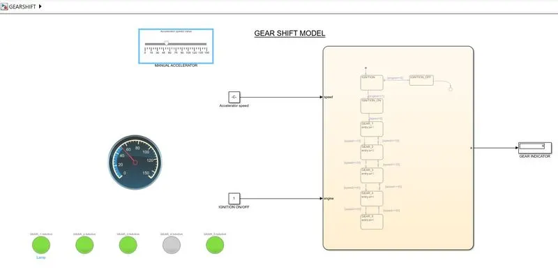
Below shown is the stateflow chart logic for gear shifting at different speed intervals.
At first the ignition condition is checked whether it is ON or OFF.
When ON condition is detected it will detect the speed given as a user input.
For speed range of 0 to 15 the output display will denote as 1st gear.
For speed range of 16 to 25 the output display will denote as 2nd gear.
For speed range of 26 to 40 the output display will denote as 3rd gear.
For speed range of 41 to 60 the output display will denote as 4th gear.
For speed range above 60 the output display will denote as 5th gear.
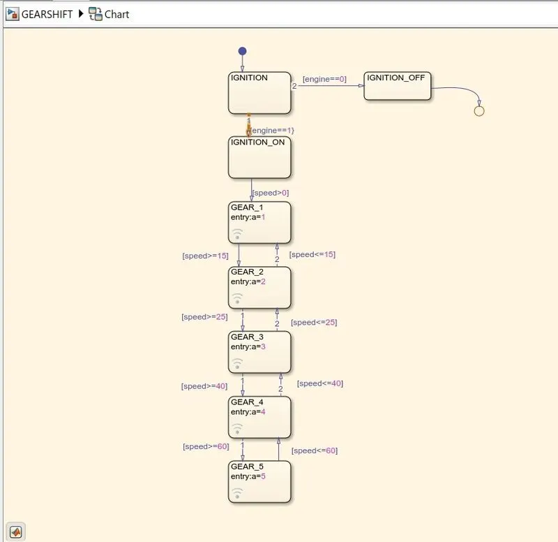
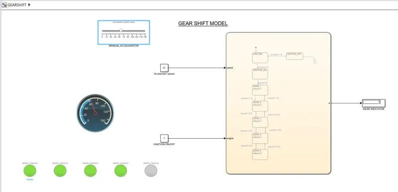
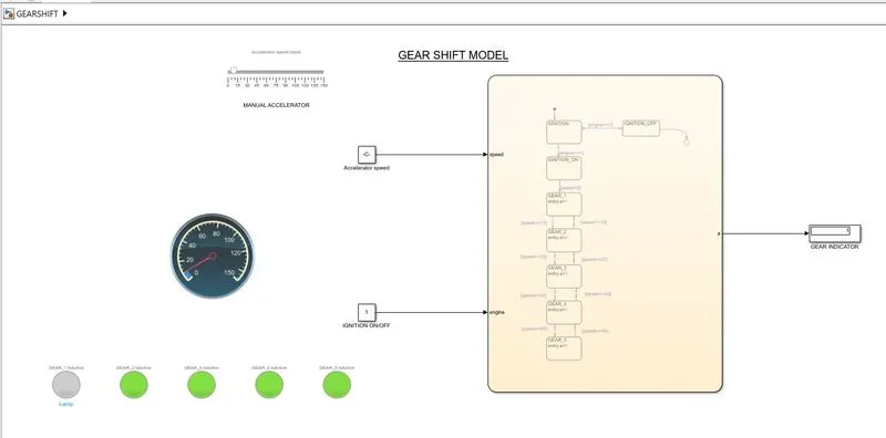
Image shown for 1st gear condition.
Here constant block denoted as accelerator speed is connected to slider and speedometer.
Below it are the lamps which blinks according to the gear conditions respectively.
Ignition block gives 1 to the input which means the ON condition.
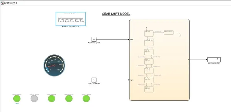
Condition of 2nd gear.
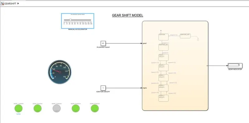
Condition for 3rd gear.
Condition for 4th gear.
Condintion for 5th gear.