Project 2 - 2D meshing on the instrumental Panel
2D MESHING ON THE INSTRUMENTAL PANEL
Aim : Using ANSA pre-processing software check for the geometrical errors and mesh the component with the given element Quality criteria. After meshing the component the thickness has to be assigned.
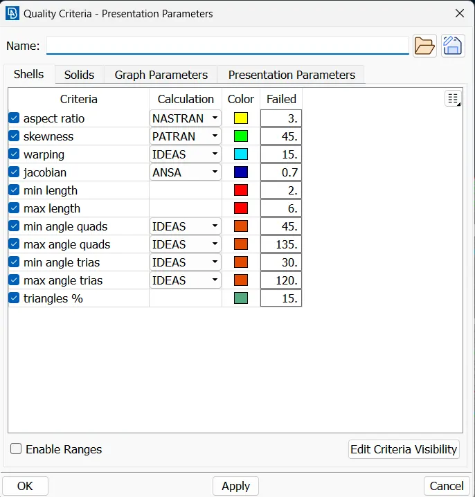
Given Quality requirements :
| S.N | Quality Criteria | Value |
| 1 | Aspect Ratio | 3 |
| 2 | Skewness | 45 |
| 3 | Warping | 15 |
| 4 | Jacobian | 0.7 |
| 5 | Min. Length | 2 Units |
| 6 | Max. Length | 6 Units |
| 7 | Min angle Quad | 45 |
| 8 | Max angle Quad | 135 |
| 9 | Min angle Tria | 30 |
| 10 | Max angle Tria | 120 |
| 11 | Tria % | 15 |
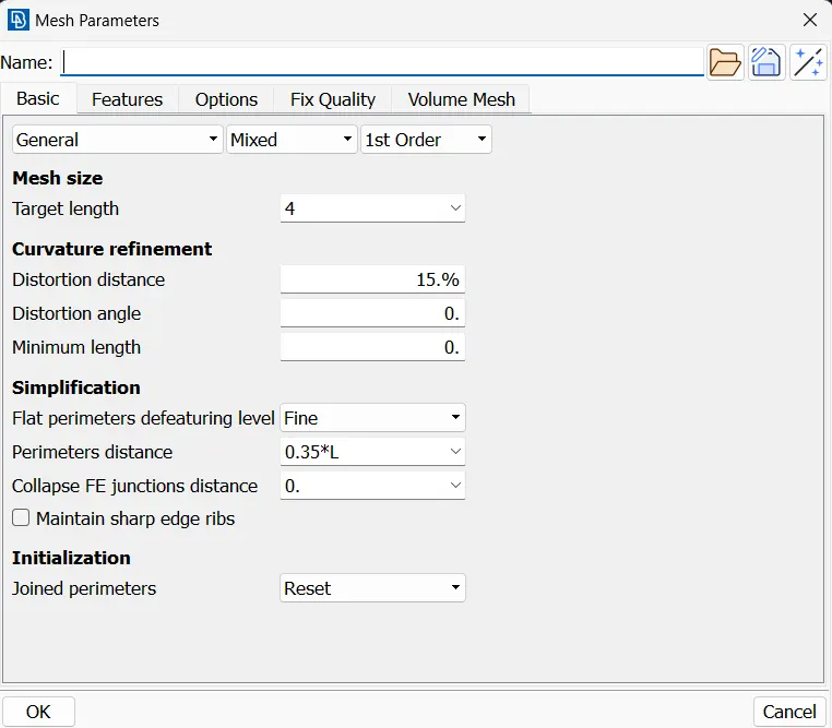
| 12 | Target Mesh Length | 4 |
Procedure :
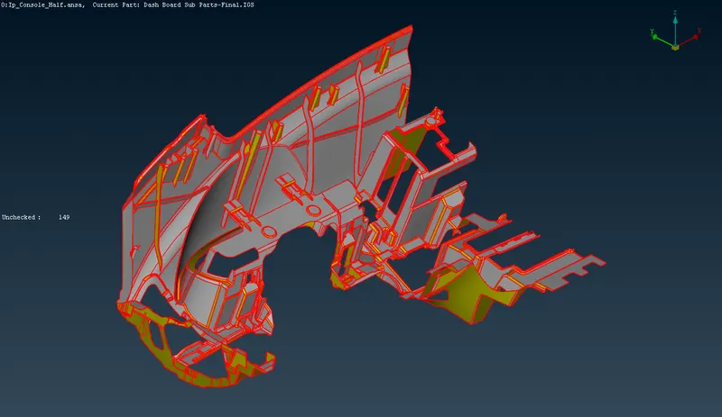
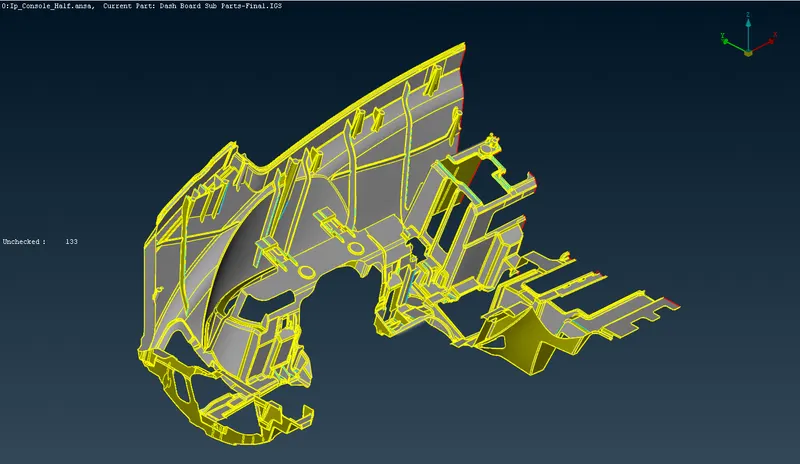
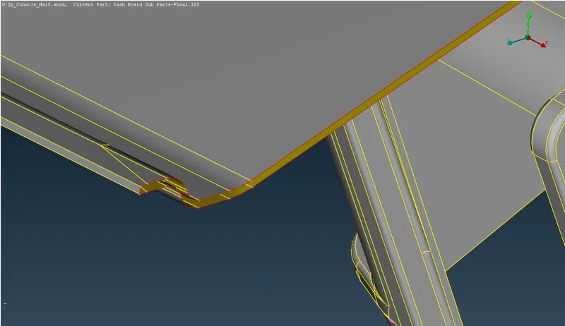
- The Instrument panel model is opened in the ansa software and the model initially contains only edges of 'single cons' indicating that the individual edges are not connected to their corresponding surfaces as shown in the figure below. The red color on the edges indicates the same.
- The 'Topo' option is used and the whole model is selected and by clicking the middle mouse button it connects all the corresponding surfaces making it a 'double cons' edges which is indicated by the color 'yellow'.
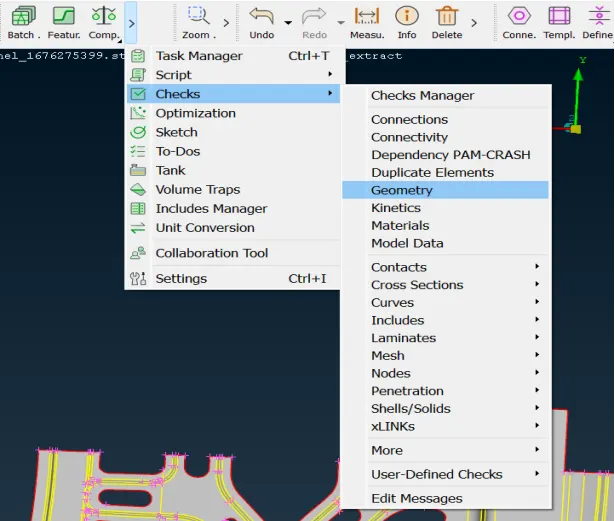
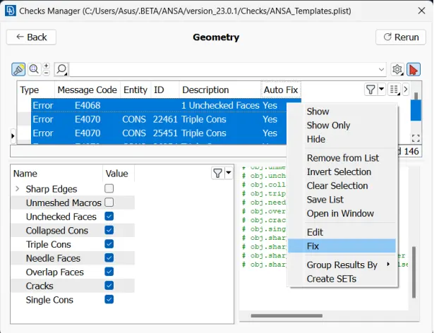
- The whole model has to checked for any geometrical error before the meshing can be started. The whole model is selected and the 'Check' option is clicked and the 'Geometry' option is selected which opens up a geometric check window, where all the required checks are selected and is executed as shown in the below figure. The single coons which is created in the model has to filled to obtain a solid model.

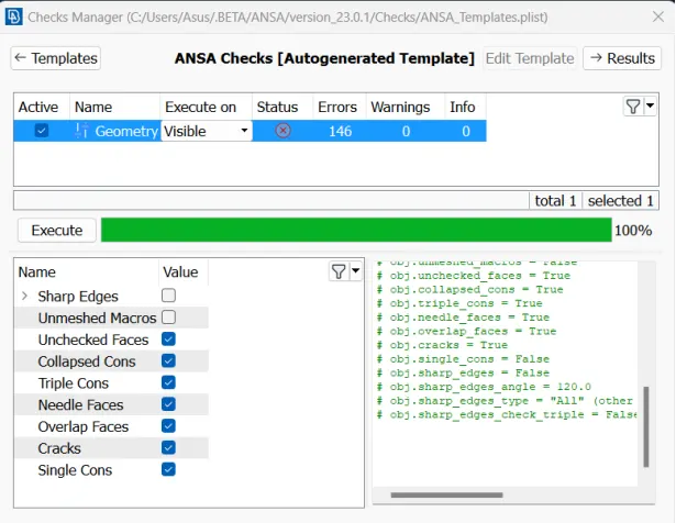
- All the errors obtained are selected simultaneously and with the right click of the mouse the fix option is selected.
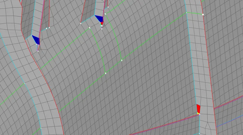
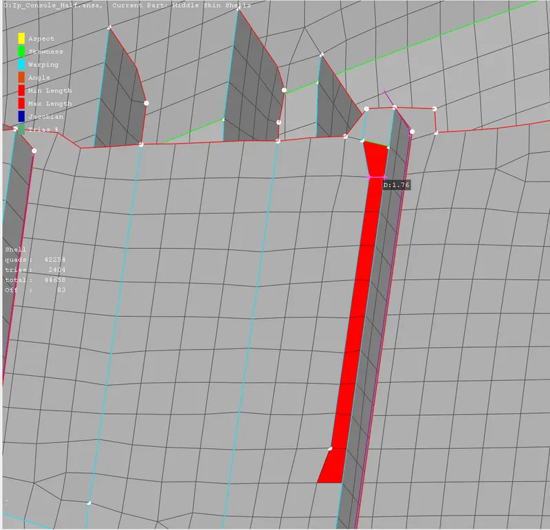
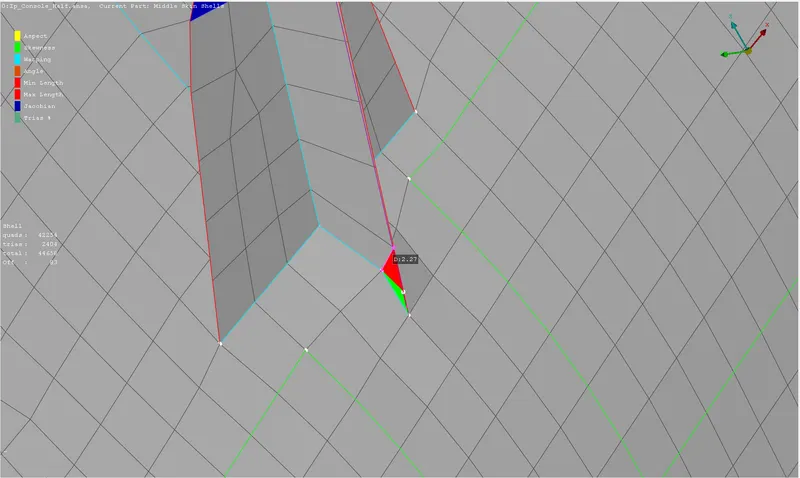
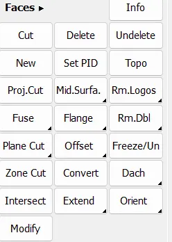
- The errors which are left are corrected manually using the commands like ‘Delete’ and ‘New’ in the Faces window.
- Once the Geometric correction is done, the F11 key is pressed and required Quality criteria is set.
- Similarly the required Mesh parameters are also set.

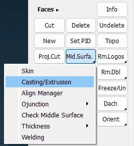
8. Once the Geometrical errors of the model are corrected, 'Casting' command is used to generated the Mid surface and the Mesh flow as per the required parameters.
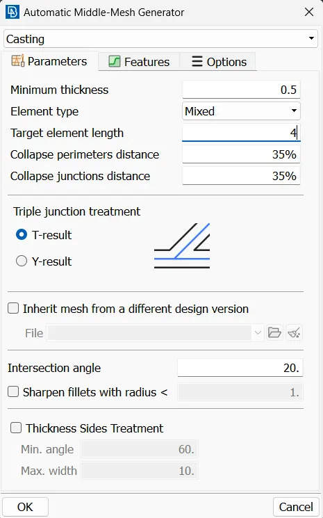
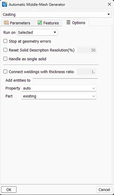
9. The command opens up a pop-up window where the minimum thickness in the whole part and the Target mesh length is specified, also since the Geometrical errors are rectified the option to stop the mesh generation on the these errors is unchecked.
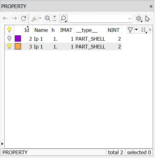
10. The Mid surface and Mesh is generated once the OK button is clicked which is as shown below. New property is created for the mid surface generated.
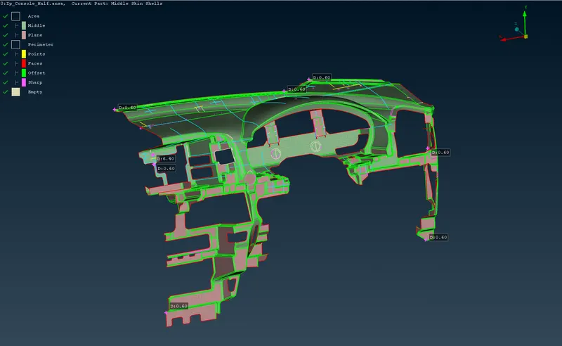
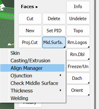
11. The 'Align manager' option is selected and the mid surface obtained is divided into further categories as shown below.
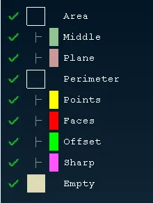
The sections are as follows.
Area -
- Middle - define Surface as a curvature (Green colour)
- Plane - Define as a Flat or plane surface (Pink Colour)
Perimeter-
- Faces - (Red colour)
- Offset - (Green)
- Sharp - (Dark pink)
Empty - they are avalilable in both Area and Perimeter. It will not define any surface and perimeter and it should be eliminated by defining the surface properly.
12. The errors obtained in the mid surface is corrected using the 'Align manager' command.
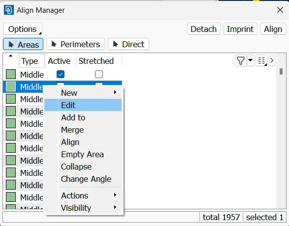
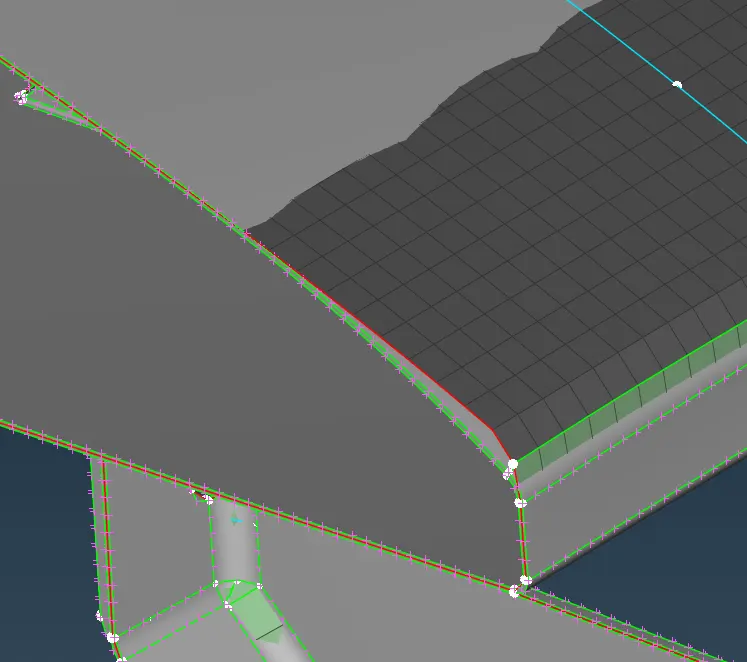
13. The section is edited to align the mesh between the model with respect to the model faces selected. The process is shown in the images below.
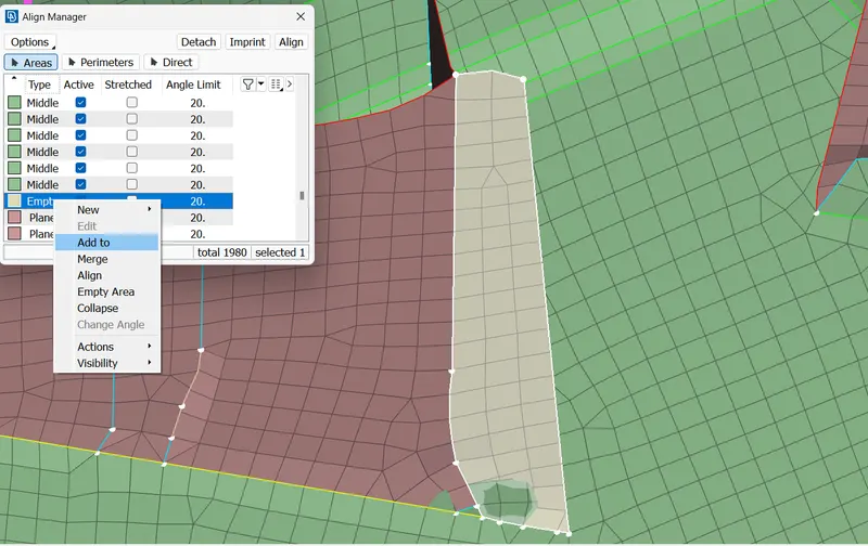
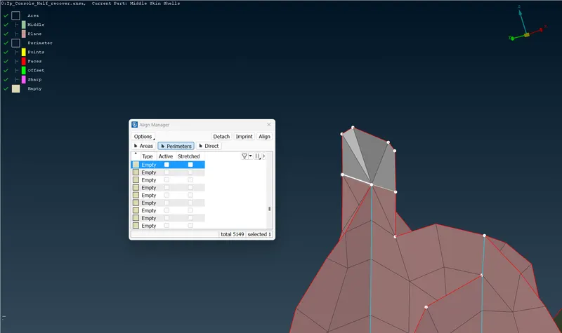
14. The Empty surfaces or the perimeter are added to the adjacent surfaces or the perimeter as shown in the figure below.
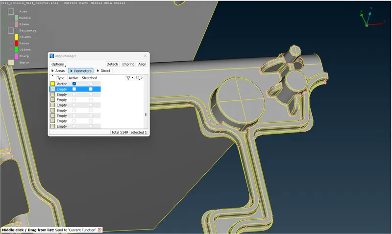
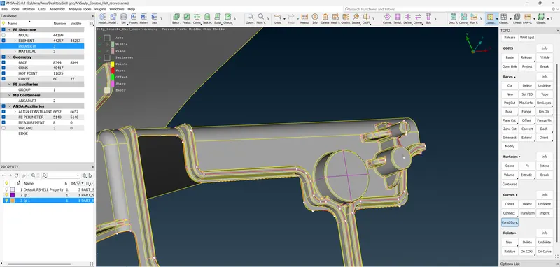
15. Creating the new mid surfaces on the surfaces shown below. The faces are cut on the surfaces and the cuts are converted into the curves using the 'Cons2curve' command as shown in the below figure.
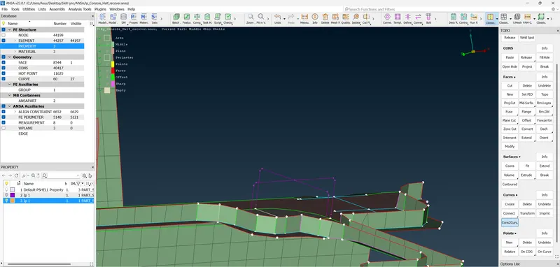
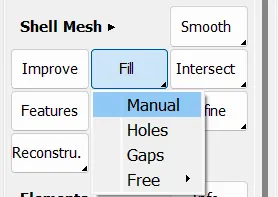
16. The gap is now filled with the mid surfaces using the 'Fill' command in the classic mesh window. The perimeters are selected and the fitted option is selected to create the mid surface as shown in the figure below.
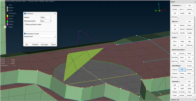
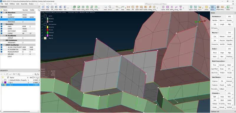
17. The newly created area are added to the adjacent areas using the Align manager and selecting the faces of the model as shown in the figure.
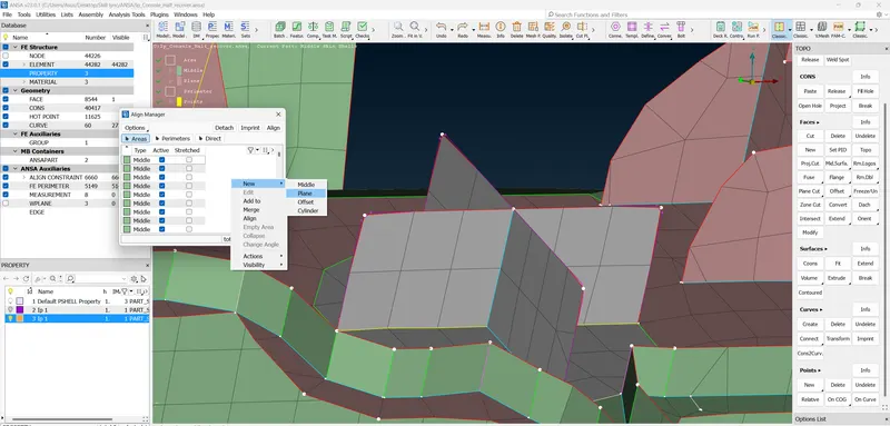
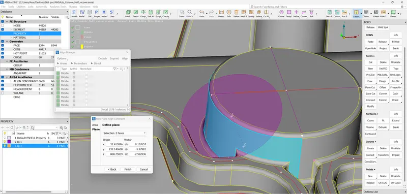
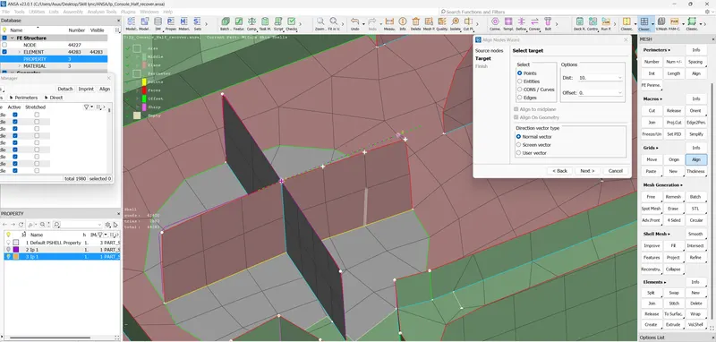
18. The newly created surface has to be aligned with respect to the surface of the model, so 'Align' command is selected in the classic mesh window and the respective nodes are selected the alignment nodes are selected as shown in the figure below.
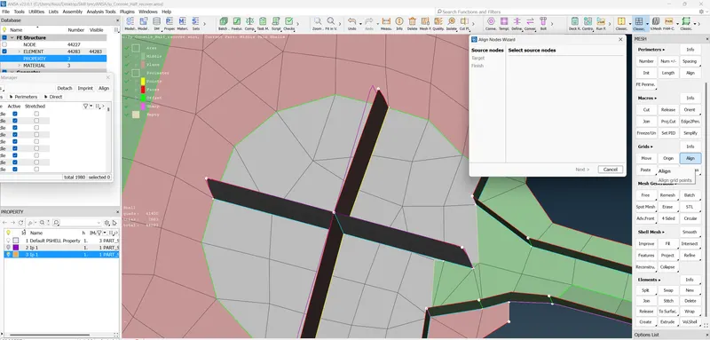
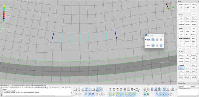
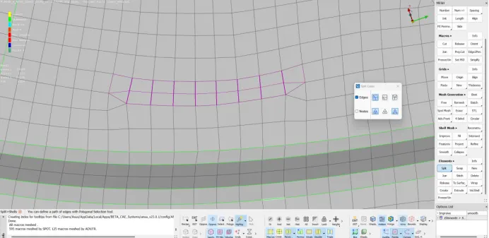
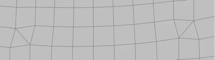
19. The Generated Mesh is optimized to meet the Quality criteria using the ‘Reconstruct’, ‘Collapse’ and ‘Smooth’ commands in Shell Mesh window, also the trias are reduced using the ‘Split’ , ‘Join’ and ‘Swap’ commands in Elements window.
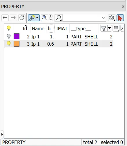
20. Once the model optimization is completed the thickness is assigned to the Mid surface in the Property window. The Quality criteria window is opened and in the Presentation parameters the ‘Draw shell as solid’ option is checked and is applied on the model.
21. The final model will have meet the Quality criteria with the minimum trias with the good mesh flow as shown in the below figure.
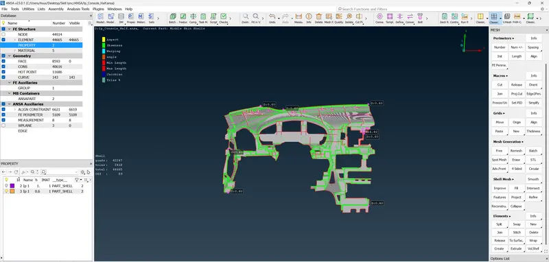
22. Since the thickness between the two surfaces is less than the minimum mesh length the quality errors around these areas cannot be eliminated. The areas are shown in the figure below.