Project 2 - 2D meshing on the instrumental Panel
AIM:
To perform FE modelling of an Automotive IP trim component by considering the given element Quality criteria.
KEYWORDS: Mid-surface Extraction, Shell Meshing.
OBJECTIVE:
- Introduction to shell meshing i.e. 2D meshing
- Geometry check & Topological error clean up
- Mid surface generation
- Meshing the geometry
The quality criterion to be followed:
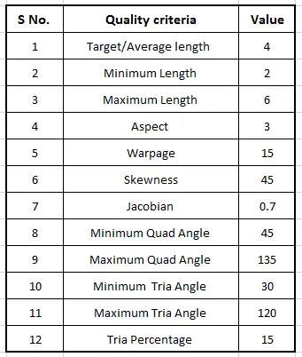
ABSTRACT: In this project, the instrument panel of the car dashboard is taken for the pre-processing stage of CAE. The pre-processing of this model is done using BETA-CAE-ANSA software. The mid surface extraction and shell meshing are mainly demonstrated here in this project. Also, the good practices to be followed during shell meshing are discussed here.
METHODOLOGY:
- Import geometry
- Topological error cleanup
- Mid-surface extraction
- Quality criterion setup
- Meshing and Mesh improvement
Introduction:
The instrument panel, as the largest inner trim part which is directly shown to the passenger, have not only beauty and function requires but also NVH and safety request. The vibration and the noise on the dashboard can be directly felt by the passenger. Thus FEA analysis of the instrument panel plays a very important role in the NVH character of the whole vehicle.
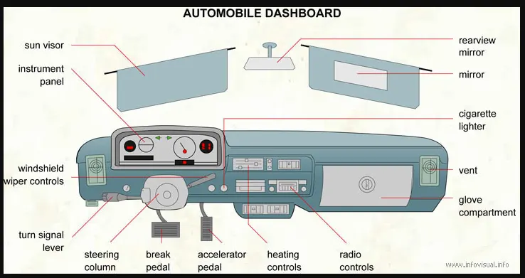
Figure. 1 Labeled automobile Dashboard
The above figure.1 shows the labeled car dashboard with the location of the instrument panel. The instrument panel assembly is installed on CCB (Crossed car beam). CCB is a structural member located under the instrument panel fixed at both ends.
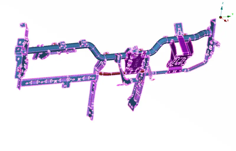
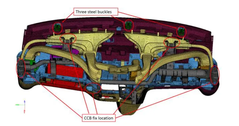
figure.2 CCB assembly
The following are some of the various types of components that are intricately arranged behind the IP surface to provide the requisite functionality:
- Substrate (usually plastic): This conceals the underlying structure, ducts, modules, etc., and is sometimes covered with foam and skin (for "soft" look and feel).
- Structural beam and supports (usually steel or magnesium): For robustness in durability, Noise/Vibration/Harshness (NVH), and crash performance.
- Ducts, nozzles, and other air handling components: For climate control of the vehicle interior.
- Miscellaneous brackets: to support wiring, components and electronic modules, and safety devices such as airbags.
- Steering column supports: The IP system is also responsible for supporting, partially or completely, the steering column. Owing to the tactile nature of the steering column response, this requirement of the IP cannot be taken too lightly.
- Other components: such as wire bundles, glove box bins, bumpers to reduce squeak and rattle, etc
Mid surface extraction
Before we discuss mid surface extraction we should know about 2D elements and why should we carry out on mid-surface?
2D Element
when two of the dimensions are very large in comparison to the third one. 2 dimensions out of 3 are known by creating a 2D element and 3 dimension data is provided by the user as additional input data
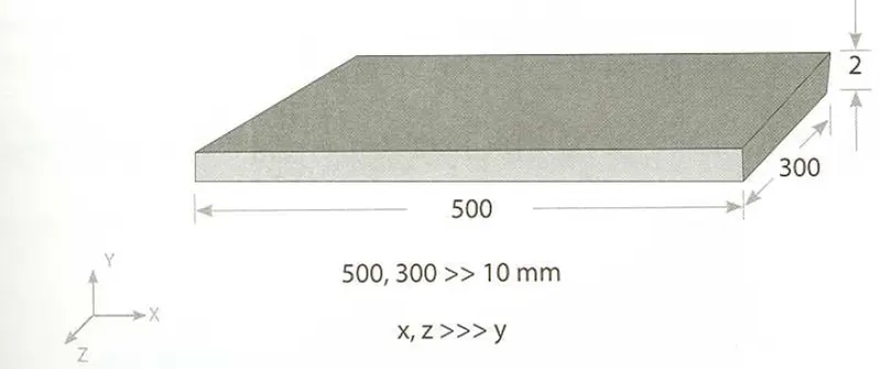
why should we carry out on mid-surface?
Element thickness specified by the user is assigned half on the top and half on the bottom side. Hence in order to represent the geometry, it is necessary to extract the mid surface and then mesh.
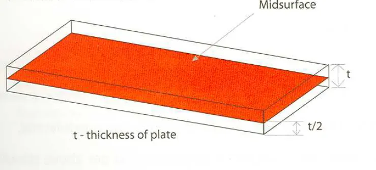
All sheet metal parts, plastic components like instruments panel, etc. In general 2-d mesh is used for a part having width/thickness ratio>20.
PROCEDURE:
Import model
Firstly, we need to import the model and study geometry.
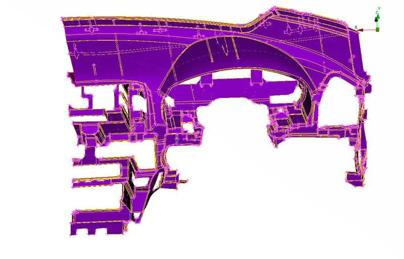
Figure. 3 Imported IP CAD model
Geometry cleanup
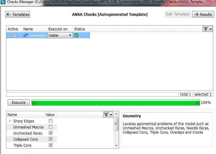
After importing geometry into the ANSA environment we observe many topological errors while doing the geometry checkup as shown below.
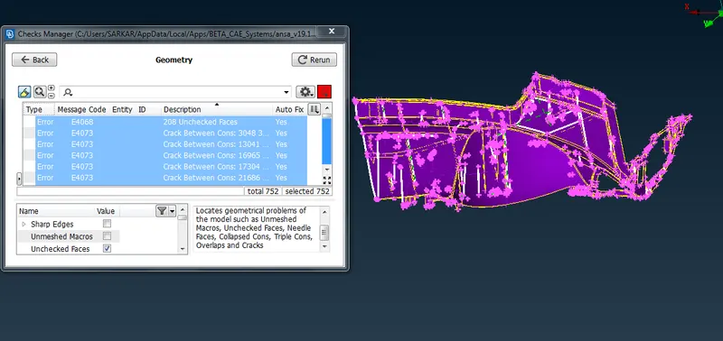
Figure. 4 Geometry checks of the CAD model
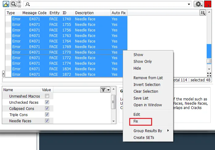
keeping the feature as a single con, triple con, crack, needle face checked, etc. click the execute button, you will see many errors. For proceeding further we need to get rid of these errors. There two options you can follow i.e. 1) manual fixing of these errors one by one or by just telling ANSA to fix by itself. If you want to fix the errors by the manual method you need one by one approach the error area and fix it by either deleting the small redundant surface, releasing the triple cons, deleting hot points, repairing surfaces, etc.
otherwise, you can use the hybrid option to minimize your time consumption by auto fixing most of the areas and rest manual fixing. The reason since mesh needs to be generated it not enough that CAD model just looks correct but instead involves cleanup aspects as well as topological aspects.
Next, we have to measure the thickness throughout the part & assure uniform thickness across the entire part. If thickness changes are observed then all alike thickness has to be kept under a separated property ID.
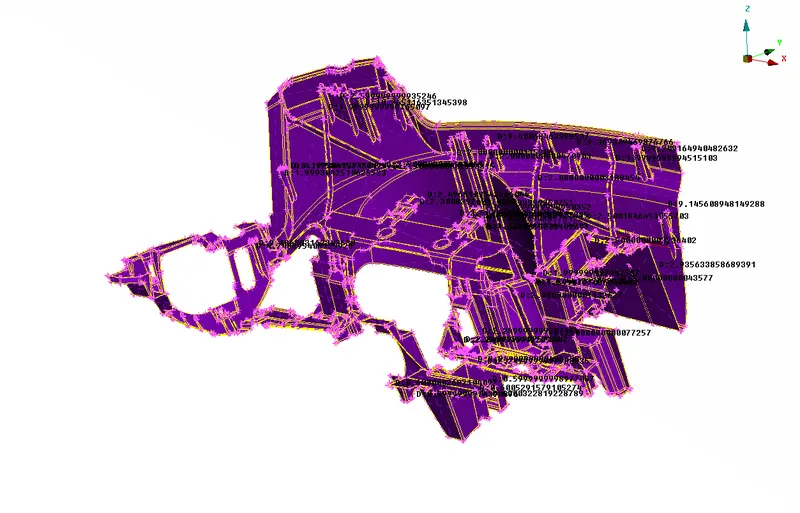
Figure. 5 Measurement of the thickness of the CAD model all over the geometry
So by measuring and storing data for thickness for sub-parts such as main panel substrate, ribs, pillars, etc.can be done so that we can extract the mid surface.
Orientation
Orientation must be checked thoroughly by the user every time working on a model. All models should have the correct orientation because the orientation issue will cause the final time issue when you merge the model with a complete vehicle. It is always preferred to maintain the continuity over the surface either grey or yellow throughout the face.
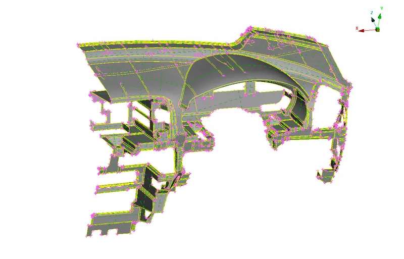
Figure. 6 Grey orientation continuity over the CAD model
There are two way to extract mid surface
1) The manual mid surface method
2) The Auto mid surface method
Manual mid surface generation
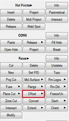
This can be done by manually selecting the surface and giving an offset option in the direction opposite to the grey surface
Note:
1) While giving the offset make sure you do not press YES or else you can delete the parent geometry
2) use Fine option under the auxiliary section in TOPO mode to get a better resolution. (select fine and click on the curved and circular areas)
Auto mid surface generation
If the geometry is closed then we can go for auto mid surface generation option but it will auto-delete the parent geometry.
steps 1) press the mid surface tab under face 2) select the full geometry 3) confirm the mid location
Here I have used the manual offset method extract mid surface as the surface thickness varies and ANSA is unable to segregate separated surfaces for auto mid surface generation.
Note:
- your parent geometry will be deleted but can be recovered back by using an undelete option. (you have to select the geometry again and do topo )
- Also, check for geometry after the completion of mid surface generation as there may be faulty surfaces created.
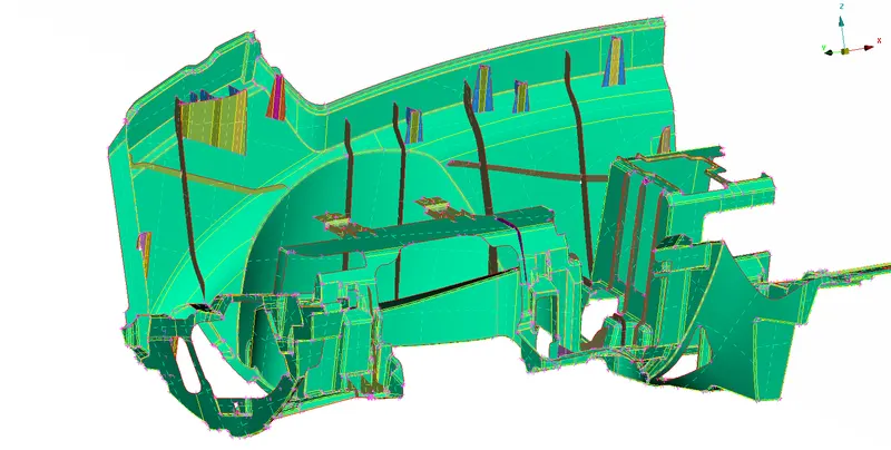
Figure. 7 Mid surface extraction of the Instrument panel
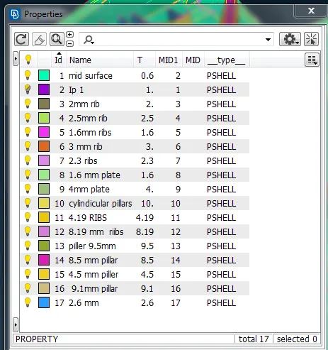
Figure.8 Property ID with different thicknesses of the Mid surface extracted.
Quality Criterion Setup
We can say that result quality is directly proportional to the element quality. The parameters like skew, included angle, Jacobian, warpage, etc. are the measure of how far a given element deviates from the ideal shape. If we talk about a square which means 90 degrees and equal side similarly equilateral triangle 60 degrees and each side equal. so we will discuss the quality criterion and try to understand them before assigning them into ANSA environment.
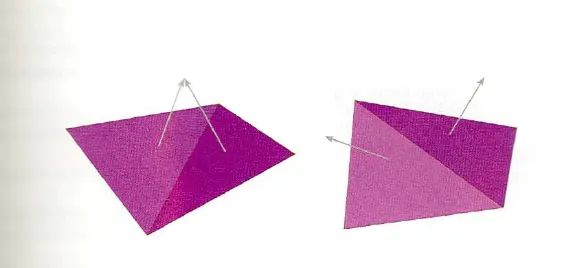
1) Warp Angle: it is defined as the angle between the normal of the two planes by splitting the quad element along the diagonal. so the maximum angle allowed between the two possibilities is called wrap angle. wrap angle is not applicable in the triangular element. the ideal value is 0 degree but less than 10 degree is acceptable as good practices.
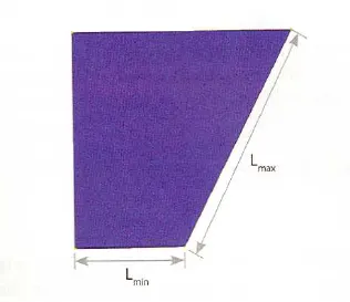
2) Aspect Ratio: It is defined as the ratio of max element edge length to the minimum element edge length. the ideal value is 1 but less than 5 is acceptable.
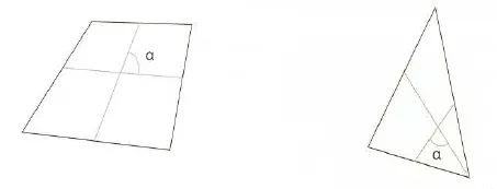
3) Skewness: If the quad element is not square and has deformation then the skewness defined for as the 90 minus the minimum angle between the two lines joining the opposite mid sides of the element and similarly for the triangular element it is 90 minus the between the line from each node to the opposing mid-side. The ideal value is 0 but less than 45 degree is acceptable.
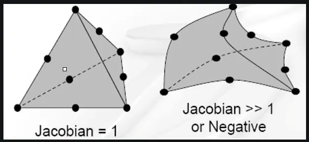
4) Jacobian: it is the scale factor used in the transformation of the co-ordinated system.(global to a local coordinate system). This is used for a faster analysis point of view. The ideal value is 1 but greater than 0.6 is acceptable.
5)Minimum element length: It is very important to check for crash analysis(time step calculation). it is also done to avoid the presence of any zero-length element.
6) Target element length: It is the size of the element by which we can get the most nearer approximate value of the result compared to the experimental result.
To set up the quality criteria press the F11 key and check the boxes of the parameters of the required quality with required values and apply
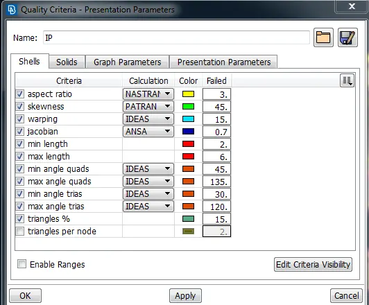
Note: At least once again check the orient and do geometry check. if all good proceed further for meshing.
Meshing and Mesh improvement
Change the mode from 'Topo' to 'Mesh' mode
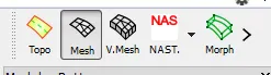
Before starting the mesh we need to set the element length. To do so we have to click the 'length' button under the 'parameters section'. After clicking the select in the pop-up window parameter and select the whole geometry and confirm enter the value 5 and confirm do the same for macros option. This alters the element length in the geometry by altering the no of hot points at the periphery as well as at your macro areas.
Also, set the meshing parameters before proceeding to mesh
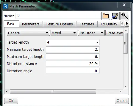
so now we can start meshing the component individually but before we start meshing we will know about the 2D meshing and its good practices to follow to get a good mesh flow.
2D Meshing/shell meshing
The type of element allowed in 2D meshing are
- Quad Elements
- Tria Elements
- parabolic Tria
- parabolic Quad
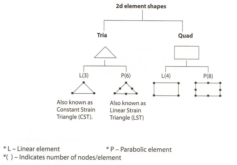
As we know that the quads elements are better than triangular elements and parabolic elements are better than linear elements
But if the quads are better than tria then what is the need for using tria elements?
- For better mesh transition
- Avoid poor quality element in a complex geometry
- better mesh flow
- Tetra meshing (trias to tetra length)
- Mold flow analysis
Best practices to follow to get better mesh flow.
1) Back to back tria element are avoided 2) on a planer surface tria should be avoided by merging them using split
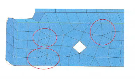
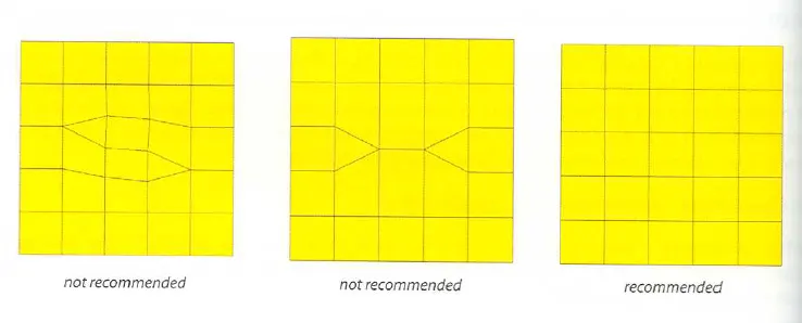
3) no mesh transition on radius fillets/Curvatures (carried to planer surface ) 4) Hole feature should be even-numbered equally spaced
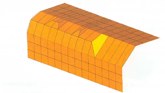
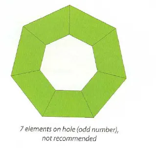
5) Avoid Trias at edges and on the features and construction lines
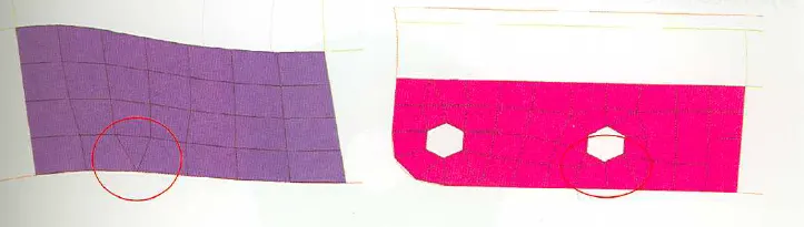
6) Avoid zig -zag distribution preferred smooth mesh(straight aligned nodes) 7) Rotating Quads are not preferred
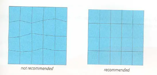
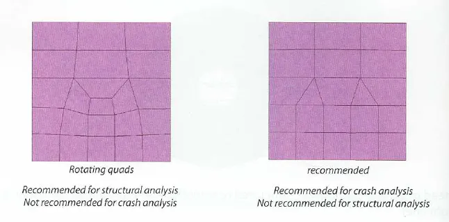
8)constant mesh size (by using tries) Is preferred due to min. element length and time step criteria
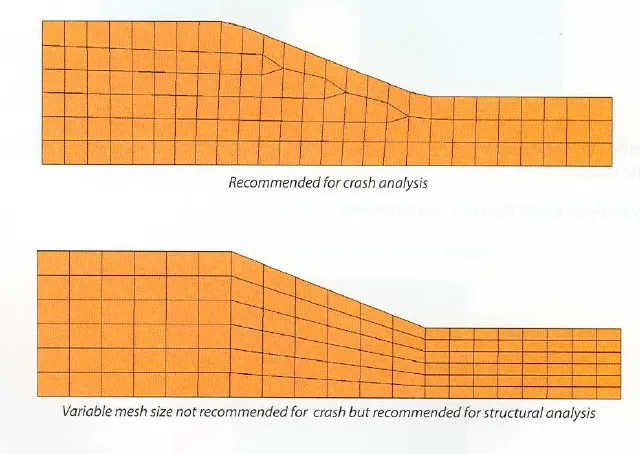
9) Remove the redundant and excess construction line to get uniform mesh flow.
10) Divide the surface near the feature into to get better mesh flow pattern
11) Defeature the areas which are going to fail the quality criteria.
12) Mesh density near the critical areas ( features) is preferred.
so as we are now aware of what are the good practices for getting a better mesh flow. Now we can start our meshing process on ANSA
We should remove all redundant and unnecessary construction lines in order to get better mesh flow.
Now we can finally start meshing the component and can get the better mesh flow by keeping in mind the best practices followed in meshing
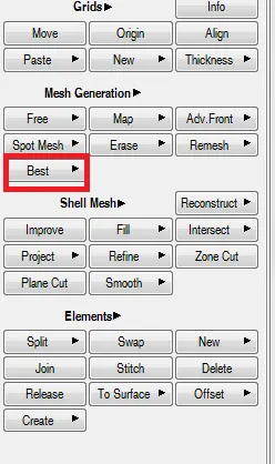
We have multiple options to mesh (shell mesh)
- Best mesh
- Spot mesh
- Free mesh
All three works on the different algorithms but here in this model, we will use the best mesh algorithm. Also after creating the best mesh we can reconstruct and smooth the mesh to get better mesh flow. ( shown below)
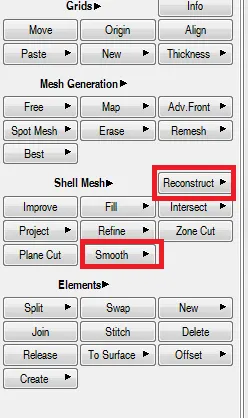
Note:
- It is always advised to select the elements for reconstructing in a square pattern rather than an irregular pattern (algorithm works best in square selection )
- It is also advised to macro area select the patch for smoothening the mesh.
Meshed Parts Results
All the parts have meshed as per quality requirement and had good mesh flow (Smooth)
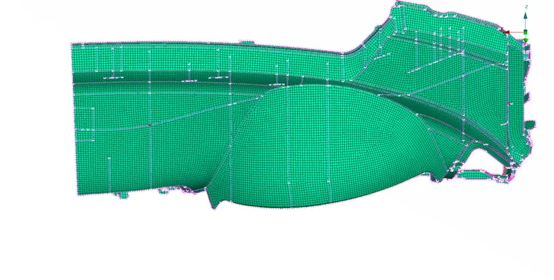
figure.9 Front view of meshed Instrument panel
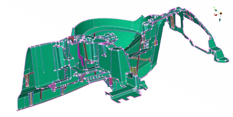
Figure. 10 Isometric view for the meshed Instrument panel
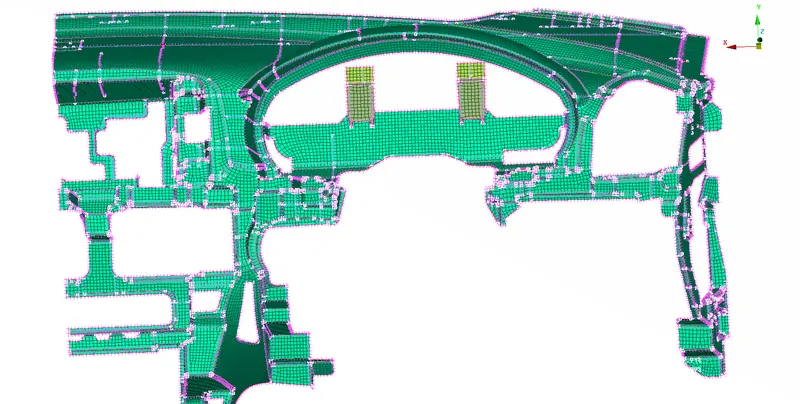
Figure. 11 Top view for the meshed Instrument panel
Difficult to capture feature and failing elements
1)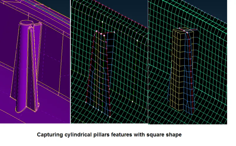
Figure. 12 Feature capturing
2)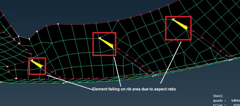
Figure. 13 Failing Rib areas
3)
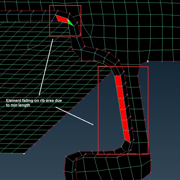
Figure. 14 min length failure near ribs
4)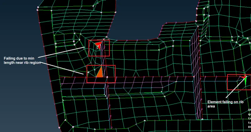
Figure. 15 Element failure near the rib region
5)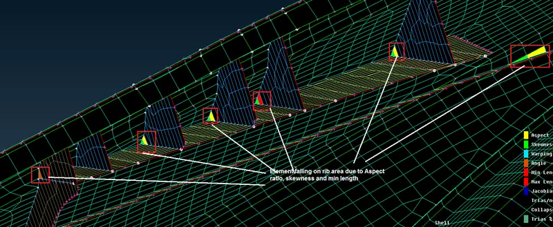
Figure. 16 Element failure near the extended rib region
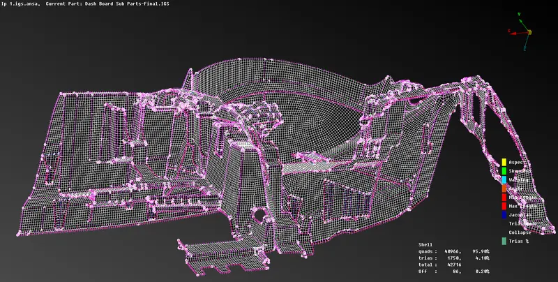
Figure.17 Hidden mode view
CONCLUSION:
The panel had been captured quite a well-using shell mesh. The total element 42716 out of which 1750 are Tria element and 40966 are Quads which makes 4.10% which is a decent percentage of Tria element(as shown in figure.17). Also, the 86 no. of elements are failing as shown above report. Most of the areas of fillets are captured using dach options and defeaturing is done in areas where construction lines are too close. The mesh flow is smooth nearer to target length as 4 mm and within the quality parameter.
LEARNING OUTCOME
- Able to fix topological error
- Able to generate mid surface for any complex geometry
- Aware of the 2D elements and shelling meshing( Quads and Tria importance)
- Aware of the quality parameters and there meaning during mesh generation
- Able to understand and implement good practices of meshing any complex geometry
- Competent in 2D meshing/ shell meshing even for complex geometry by achieving better mesh flow.