Project 2 - 2D meshing on the instrumental Panel
Objective:
For the given instrumental panel (half the size of the original instrumental panel), geometrical errors needs to be checked, and proper meshing is to be done with the help of casting method and align manager.
The following quality criteria is required for the meshing.
|
S.No |
Quality Criteria |
Value |
|
1 |
Target/Average length |
4 |
|
2 |
Minimum Length |
2 |
|
3 |
Maximum Length |
6 |
|
4 |
Aspect |
3 |
|
5 |
Warping |
15 |
|
6 |
Skewness |
45 |
|
7 |
Jacobian |
0.7 |
|
8 |
Minimum Quad Angle |
45 |
|
9 |
Maximum Quad Angle |
135 |
|
10 |
Minimum Tria Angle |
30 |
|
11 |
Maximum Tria Angle |
120 |
|
12 |
Tria Percentage |
15 |
Procedure:
To complete the required objective, following steps are followed.
Step 1) The CAD file is imported into ANSA and Resolution is fixed by changing the length and macro parameter from the Toolbox “Mesh > Classic > Perimeter's > Length”.
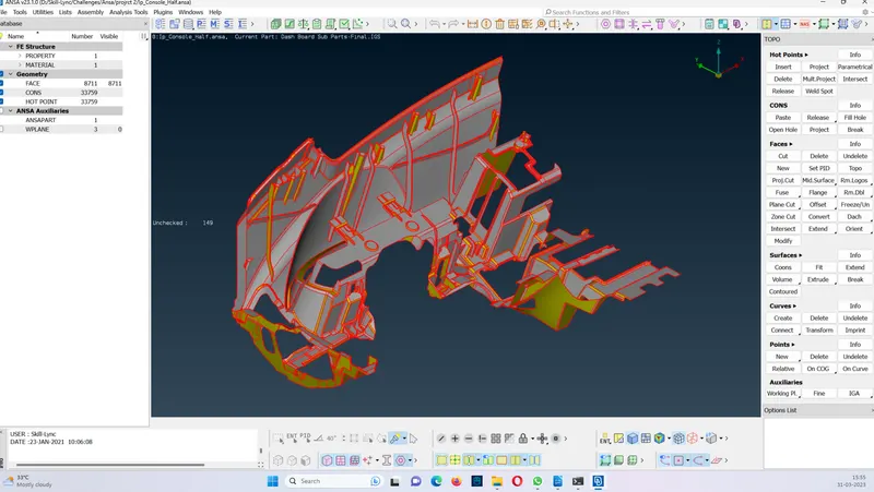
Step 2) Topo is done on the geometry from the toolbox “TOPO > faces > topo”.
And then check up for the geometrical error is done from the toolbox Check >geometry. The errors are than auto fixed.
Some of the errors were not fixed while doing the auto-fix. To fix these errors following tasks were performed as required.
1) Deleting unnecessary hot points
2) Releasing Cons and pasting them or doing a TOPO
3) Releasing the Cons and creating a face between them
4) Deleting a face and creating a new face
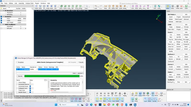
The given CAD geometry is half of the parent geometry, so to avoid the single con errors, the edges and corners are closed with new faces.
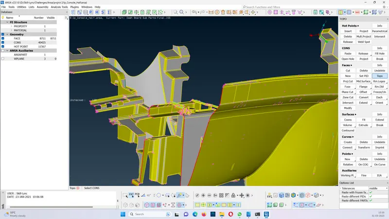
Figure: Geometry with open ends at the cut-off end
Step 3) In this project Meshing is completed with the casting method , where mid surface is not generated as an intermediate step. The tools for the casting are selected from the toolbox TOPO > Faces > Mid. Surface > Casting
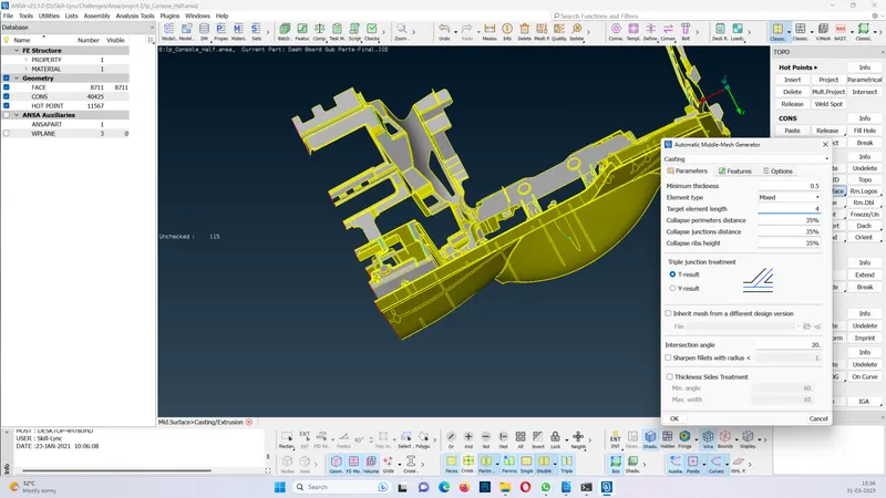
After fixing the given quality criteria, the mesh was then generated as below.
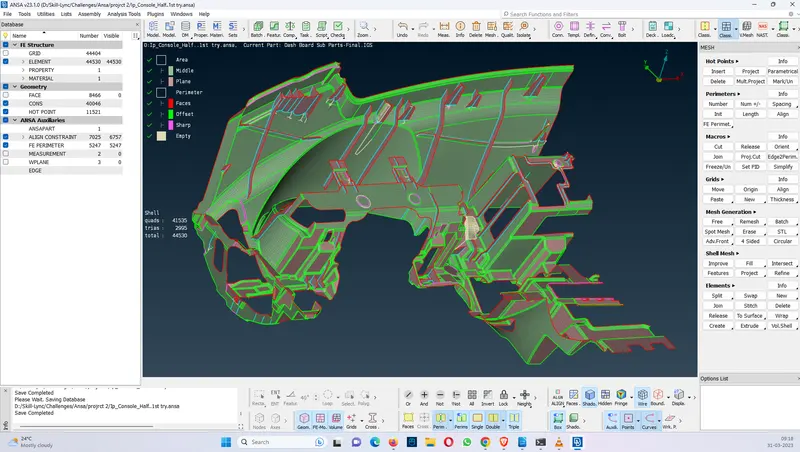
Figure: Mesh done with the casting process
Step 4: The corrections in the generated mesh with respect to the parent geometry is done with the help of Align manager.
Tools used to correct the shell mesh are:
a) TOPO > Faces > Mid.surface > Align Manager
b) Curves > create
c) Curves > connect
d) Shell Mesh > Fill
e) Hot points > Insert
f) Grids > Paste
g) Grids >Align
h) Macros > Cut
i) Macros > Join
j) Elements > Delete
k) Faces > Intersect
To use the align manager the shell area/ perimeter needed to be aligned with the parent geometry is first selected in the FE elements and then windows open up for selection of middle etc. The surfaces which are not uniform can be deleted and reformed using the fill option from the shell mesh, then the newly created FE element can be merged with the help of align manager.
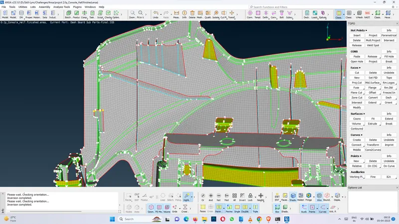
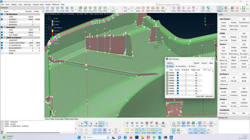
Conclusion: The Align manager helps improve the shell mesh with giving an option of deleting the unwanted or erroneous mesh and then manually creating it and re-aligning it to the parent geometry.