Project 1 - Meshing of Floor Panel
Objective:
The objective of this project is to perform pre-processing by importing given Floor panel CAD model in ANSA which includes geometry clean-up, mid-surface extraction and 2-D shell meshing.
The generation of mesh should full fill the following quality criteria,
|
S.No. |
Quality Criteria |
Value |
|
1 |
Taper |
0.5 |
|
2 |
Minimum length |
2 |
|
3 |
Maximum length |
8 |
|
4 |
Aspect |
5 |
|
5 |
Warping |
15 |
|
6 |
Skewness |
45 |
|
7 |
Minimum quad angle |
45 |
|
8 |
Maximum quad angle |
135 |
|
9 |
Minimum tria angle |
20 |
|
10 |
Maximum tria angle |
120 |
|
11 |
Tria percentage |
10 |
Floor panel CAD image:
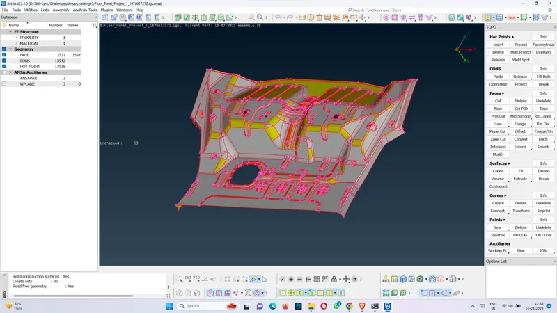
Fig. CAD model
Procedure:
1. First the Floor panel model is imported into ANSA software.
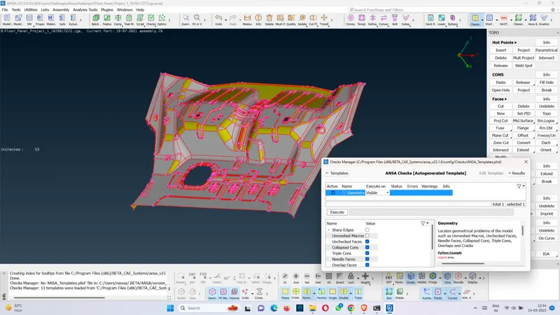
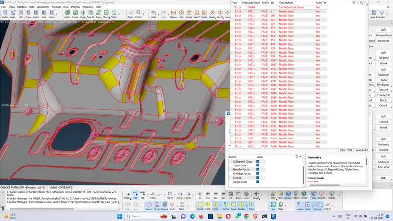
2. After importing the cad file into ANSA, the first steps are to check for the geometrical errors, as there might be several missing surfaces, intersecting surfaces etc. due to the format conversion process from importing it in ANSA from a supported or unsupported CAD file format, or inherent bad model. For the given CAD model I didnot correct all the erorrs which were not improved by using the fix option in check>geometrey tool box in the parent geometry because there were lot of errors and instead corrected the geometrical error of the mid surface obtained from the parent geometry.
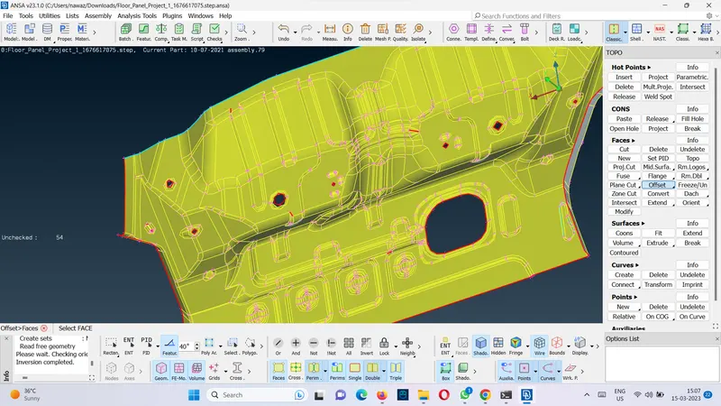
3. Extraction of mid surface
The mid surfaces are extracted here using the tool Faces>offset and choosing feature tool with angle 40 degree, which includes offsetting the surfaces of all the faces towards the middle section of the given geometry. Offsetting is done by clicking on the tool and then selecting one of the surfaces and then clicking the middle button.
Extracted mid surfaces are then primarily checked for geometrical errors and if any error is found then it is corrected as described.
The following steps are followed to clean up the geometry.
-
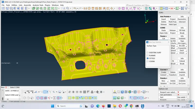
Faces>Topo – We first perform “topo” from the faces in ANSA to ensure that all the surfaces are connected properly.
-
Checks>Geometry- The next step is to perform geometry checks by going to checks toolbox and run it for parameters as shown in the image.
-
Fixing errors- Most of the errors can be fixed by selecting all and then chose fix from mouse-right-click option. Some errors are fixded by deleting the faces with errors adn then creating a new one form the toolbox faces.
-
Faces>Orient- The orientation of all the faces is modified by going to Faces toolbox. This ensures that all the faces are oriented similarly.
4. Mesh creation
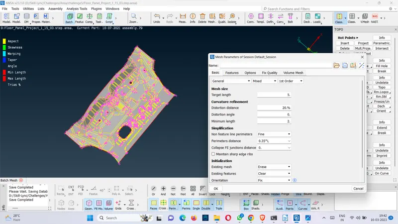
The next step is to create the mesh. First the mesh parameters are configured by going to utilities>mesh parameters. There the target length, minimum element length and maximum element length are configured respectively.
Secondly, the quality criteria as required in the challenge by going to utilities>quality criteria is fixed. And the quality criteria file is stored for future reference.
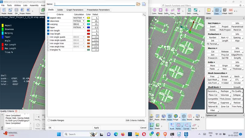
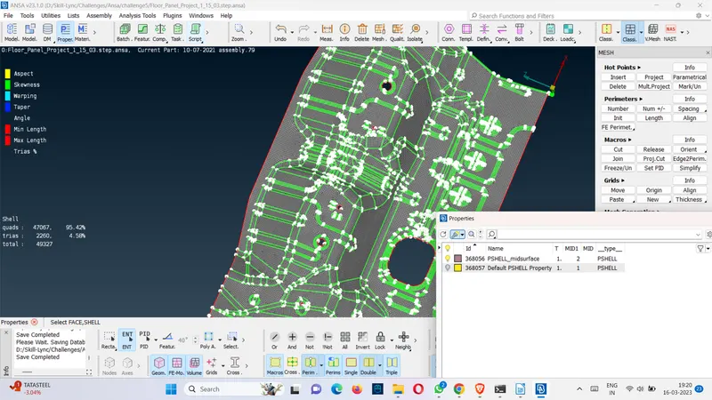
Now to create the mesh the mid surfaces are prepared by adjusting the value of length to 5 by going to perimeters>length in the mesh module. All the CONS are selected and target element length 5 is fed as length value. It’s “5” for all the Macros (surfaces) also.
Meshing is done using the Batch tool. In this a new meshing scenario is created for the selected mid surface and the mesh parameters and quality criteria as given in the objective is fixed. Then, the mesh is generated.
The created mesh is refined using the Shell Mesh>Reconstruct tool. It is ensured that there are no rotating quads. Also, trias are kept as low as possible. While dealing with trias, the following things need to be ensured.
-
No back-to-back trias touching each other
-
No opposite trias
-
No trias touching the edges
-
No trias on a feature
-
Low concentration of trias in a region
To deal with trias, the following tools are used,
-
Grid>Paste, to paste the nodes and move tria backward
-
Elements>Split, to split an element and move tria forward
-
Elements>Swap, to move the tria left or right
-
Elements>Join, to join two trias to make a quad
After modifying the mesh, Shell Mesh>Smooth tool is used to smoothen the flow of the mesh. Any elements failing for quality criteria are also fixed by either re-meshing or smoothing the elements.
Conclusion: The pre-processing of the given CAD geometry is achieved and the meshing with the required quality criteria has been achieved.