Project 2 - 2D meshing on the instrumental Panel
1.
For the given component, check for the geometrical errors and mesh with the given element Quality criteria. After meshing the component the thickness has to be assigned.
Write a detailed report on your meshing process and also mention which method you used to extract the mid-surface along with the reason.
|
S.No |
Quality Criteria |
Value |
|
1 |
Target/Average length |
4 |
|
2 |
Minimum Length |
2 |
|
3 |
Maximum Length |
6 |
|
4 |
Aspect |
3 |
|
5 |
Warpage |
15 |
|
6 |
Skewness |
45 |
|
7 |
Jacobian |
0.7 |
|
8 |
Minimum Quad Angle |
45 |
|
9 |
Maximum Quad Angle |
135 |
|
10 |
Minimum Tria Angle |
30 |
|
11 |
Maximum Tria Angle |
120 |
|
10 |
Tria Percentage |
15 |
- Procedure.-
- Import geometry:-
first of all model created by design engineer based on requrement but that engineer is not understand about this model is good or bed then ansa software required for the check the quality criteria.
First of all import a file of model_in ANSA softwere(ANSA V.22) (FILE>OPEN> MODEL)
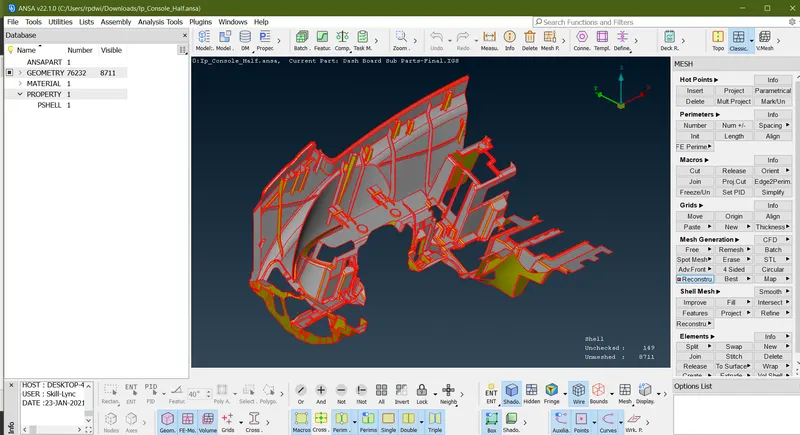
2) Perform a Geometrical clean up:-
- Here we will be doing some geometry checks on the parent component.
- To fix the geometry checks go to (Tool Bar >Checks>Geometry)
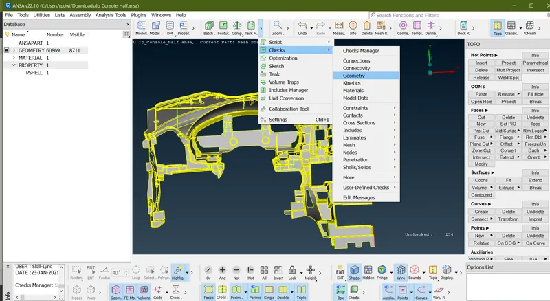
-
Terminologies for Geomerty Options -
- Unchecked faces - Faces that failed for the shadow operation.
- Needle Faces - Degenerated faces are faces that have their opposite CONS coincident.
- Collapsed Cons - A CONS where it's starting and ending position coincide.
- Triple Cons - Areas where three or more faces have a common boundary.
- Cracks - Red CONS at inner areas.[Holes are excluded].
- Single Bounds - Red CONs at outer areas.[Holes included].
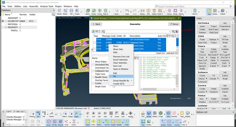
-
As shown in above image here it was 531 error present.
you have two method to fix this error either go mannual or go auto fix method.
Manual Method- First Go (check manager> check geometry> Execute)
In Above image here 531 error go triple cone and right click of mouse new option pop-up where click show only so in this operation wher this error persent that area highlighted than remove manualy this are and using topo.
Auto Fix Method-First G0(check manager> check geometry> Execute)
In This method Select all error's in Ctrl+A Or click left click of mouse and Drag mouse upword & downword direction and than a right click of mouse and than choose FIX option
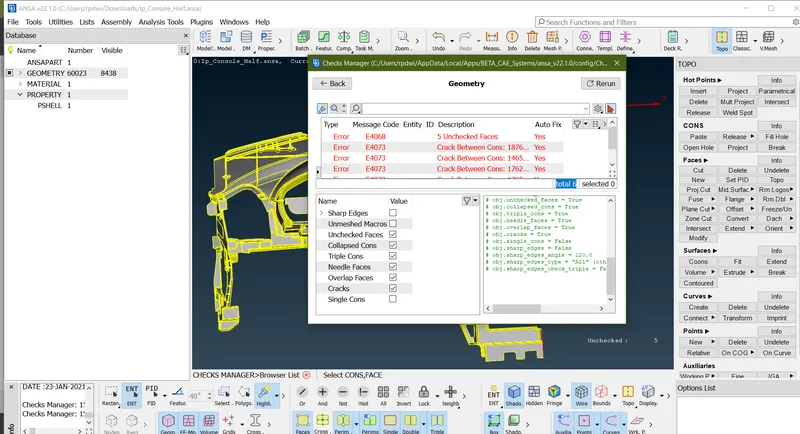
- As show in below image after performing auto fix only 6 error present in model, Errors that should be Fixed by Manually or once do auto fix thus that less error showing in the geometry.
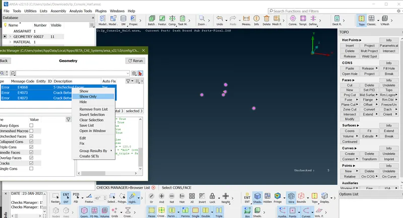
- Only 3 error present to solve this to go manually or delete the face and create new one with the help of (TOOL>FACES>NEW>Select the surface )
NO ERROR(Error Fixed By manualy method)-
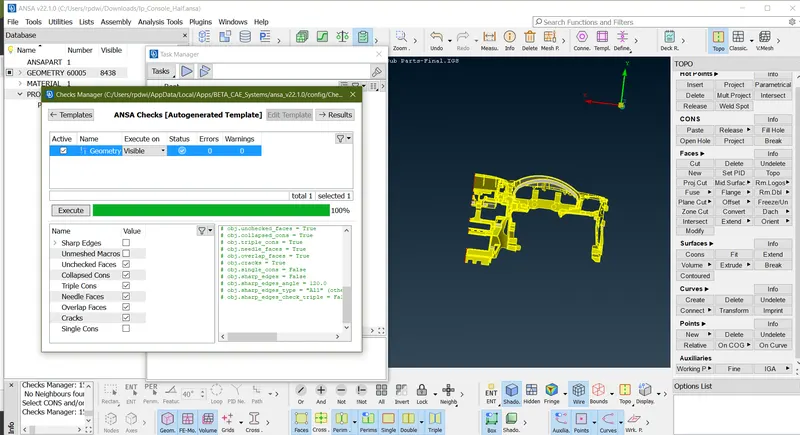
3) Quality criteria and parameter:-
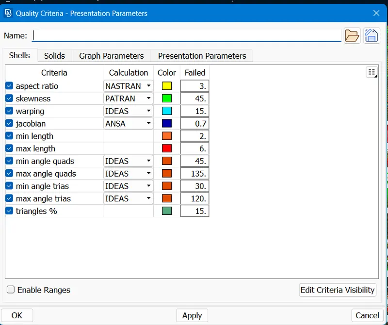
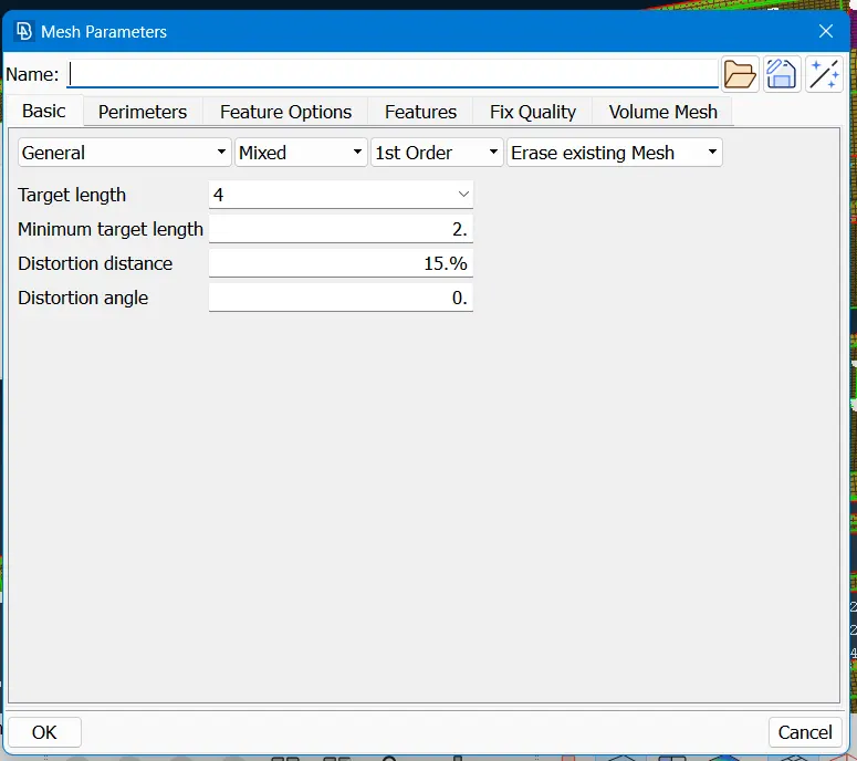
4) Generate mid-mesh by casting method:
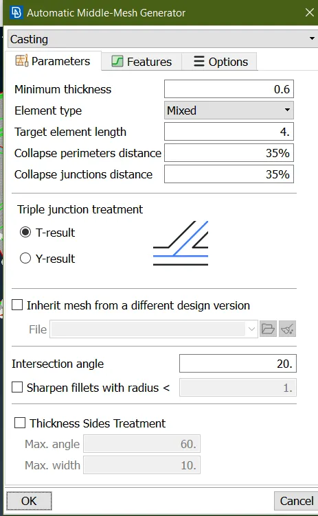
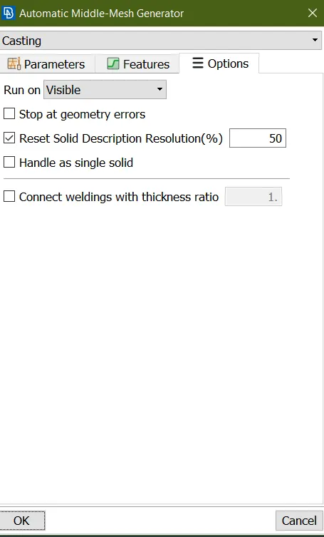
- This makes the component to get a desired shape,So it will be easy to extarct a mid-mesh without any errors.The possiblities of errors will be less.
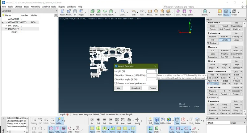
- To give perimieters and macros length on the componets,
- Go to (Mesh Module >Perimeters>Length.)
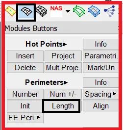
- Simillarly do the same thing for the macros also.
Why to Extract Mid Surface ?
- Before extracting the mid surface for every component,We should measure the thickness of the component and then we have to proceed to extract the mid surface.
- If the component thickness is less than 6mm then we will come to know it is a sheet metal component.
- For sheet metal and plastic components,Mid Surface extraction is must.
In this project i'm using Casting method to genarate MID-MESH.In this method Genarate Mid-Mesh taken Very less time as compare to other method.
30 min taken to genarate Mid-Mesh automatic by using Casting method.
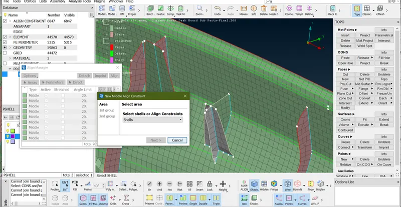
Below image represent once casting proces done. once cating is done mid-mesh are hidden in perent geometry to visible mid-mesh by using Faces off to switch to micro option and open align manager by (Topo>Faces>midsurface>Align manager)
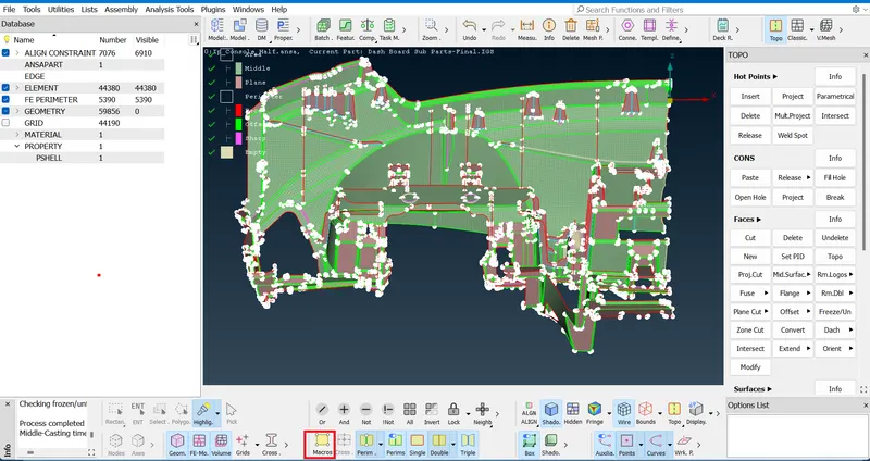
Switch Topo To Classic mesh showing mesh.
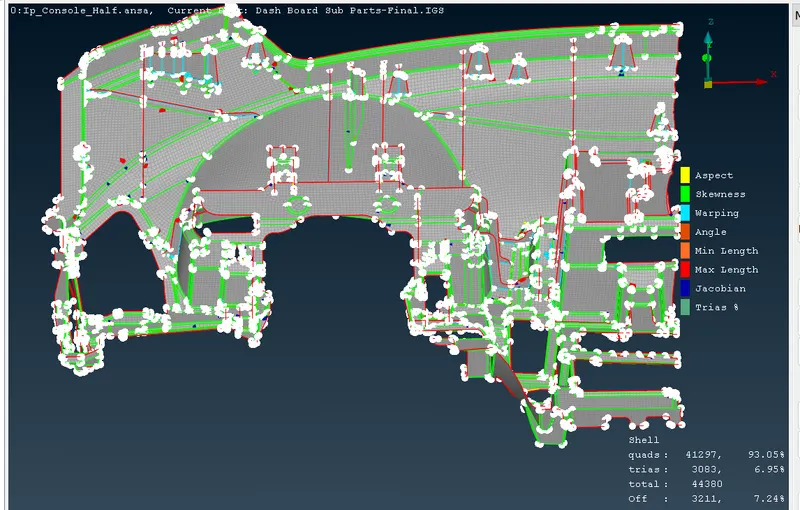
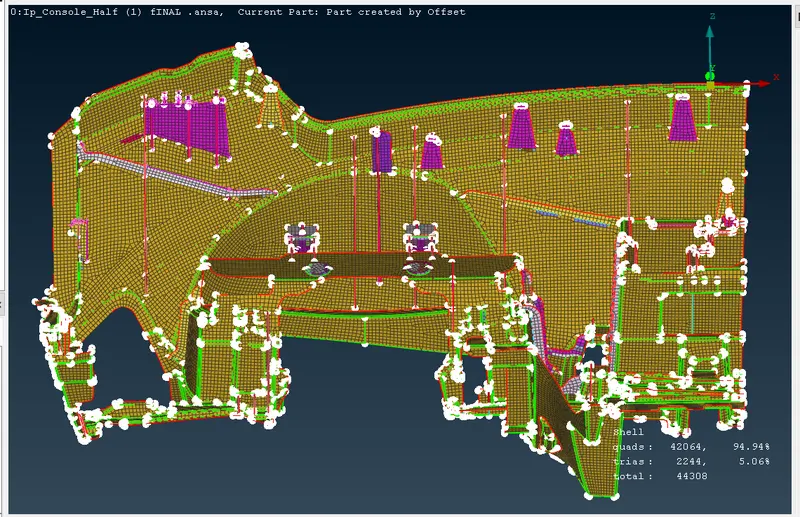
Below image once the meshg is done 3211 Off Element 7.24% And 3083 Trias 6.95% Abilable.
elemenate off element And Trias as much as i can.
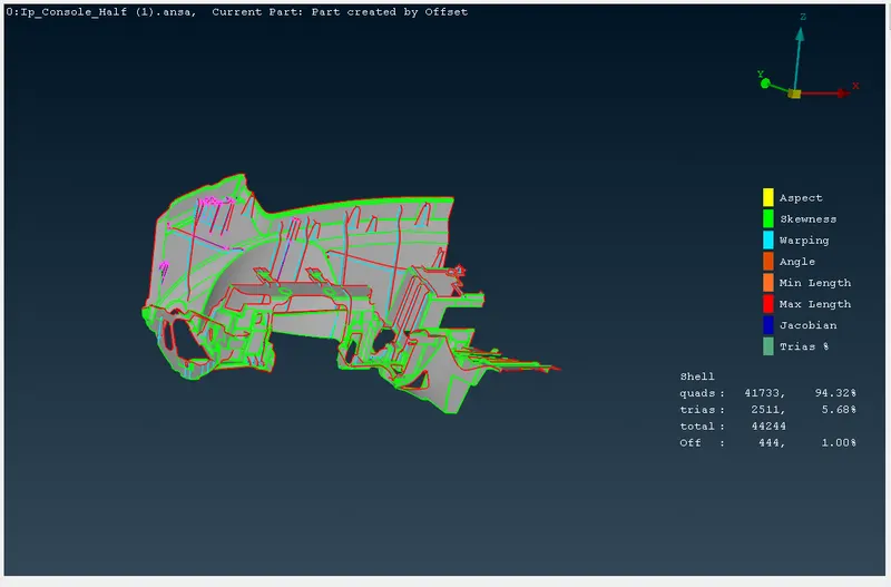
Below image result is approprate and achiving 1% off element and 5.68% of Trias.
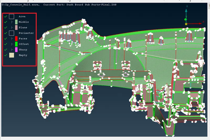
in Casting process Align manager defining Area And parameter
Area-
Middle- define Surface as a curvature (Green colour)
Plane - Defgine as a Flate or plane surface (Pink Colour)
Parimeter-
Faces-( Red colour)
Offset- (Green)
Sharp-( Dark pink)
Empty- this is not define Any surface and parameter it should be elemenate.
- showing Empty By (Select all empty>right click of mouse>Visibility>Show only)
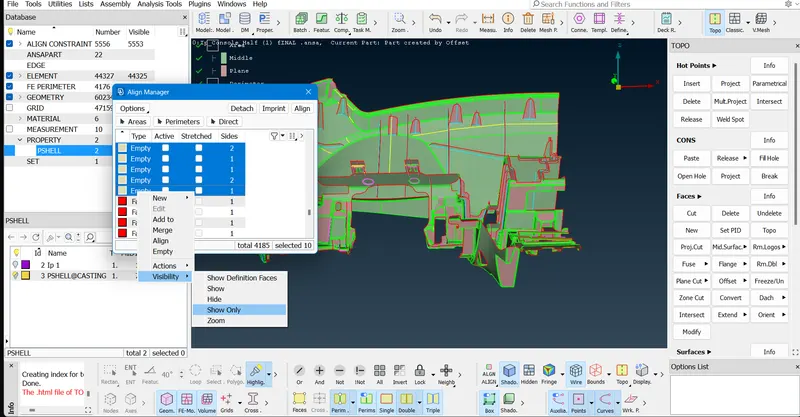
Here is empty surface as below image.
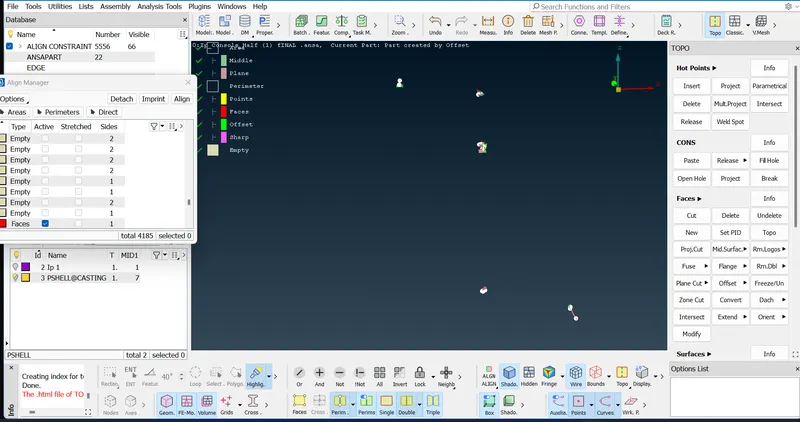
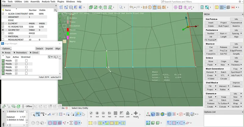
- to fix this kind of error by using paste option (Clasic mesh>Grid>Paste>Select one node and second node>middle click of mouse)
- Once the pasteing node is done than tongle the line which is not required by using Right click of mouse button.

Tongle the line by iusing (Clasic mesh>Macros>Join>Select the line)
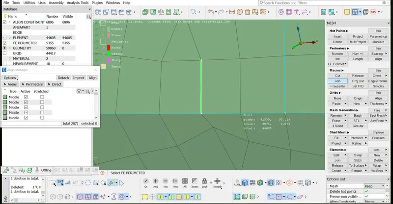
in below image having empty parameter first define as a parameter line by using (Topo>Open align manager>Select the empty line>right click in empty>edit >faces>middle click)
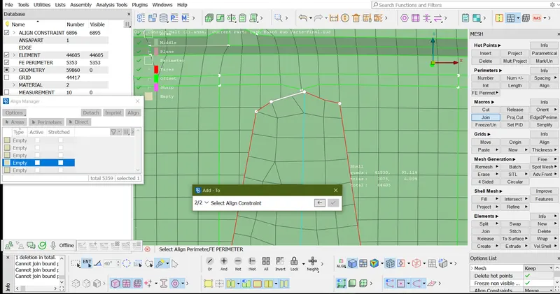
parameter assign. showing below image.
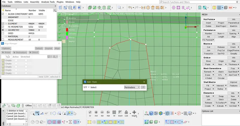
in below image dog house not in proper way because its having sharp edge first delete the surface and recreate the dog house by using delete option.
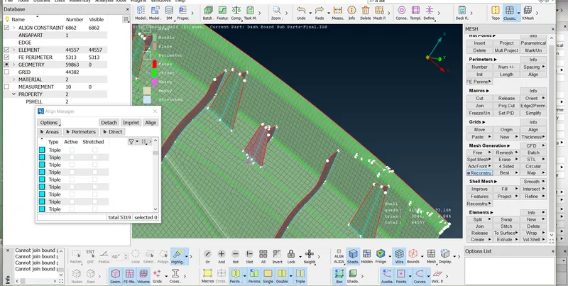
once the dog house surface deleted than tongle all the White or empty edge by using (Classic mesh>Macros>Join)
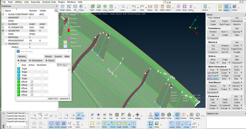
Tongle sharpe edge line
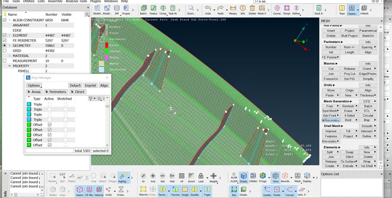
- tongle the line or doing above operation construction line not in a stright way so first achive straight line.
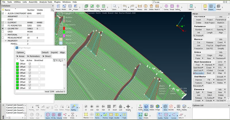
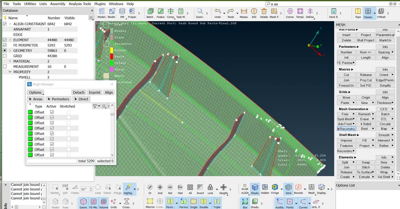
- Select the line and use Align manager,two point option
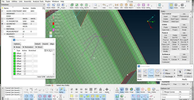
- To create the surface first by using (Topo>Curve>Create)
- To create the surface by using (Classic>Shell mesh>Fill>Select the curve/Parameter>middle click of mouse)
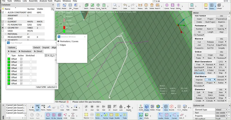
- Than Select method By Draft to coons> ok
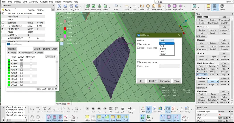
- Surface created as Showing in below image.
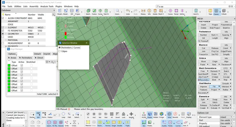
- Now the create second surface, first Go to (Classic>Shell mesh >Project>select the Shells by macro >Next)
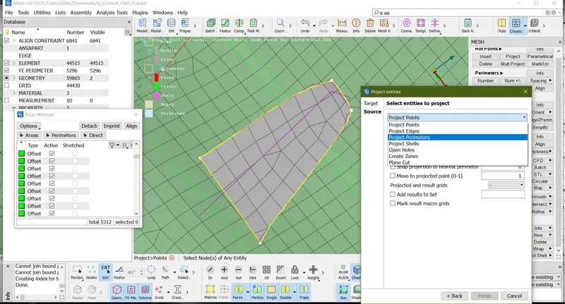
- Select entety to project Project Perameters>Finish.
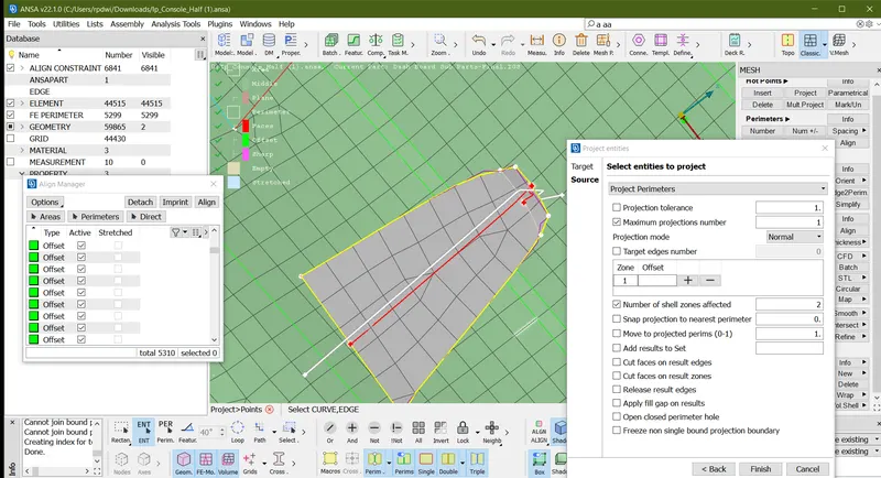
- Line projected as showing in below image.
- Once the line project tongle all the empty line. by using (Classic>Macros>Join)
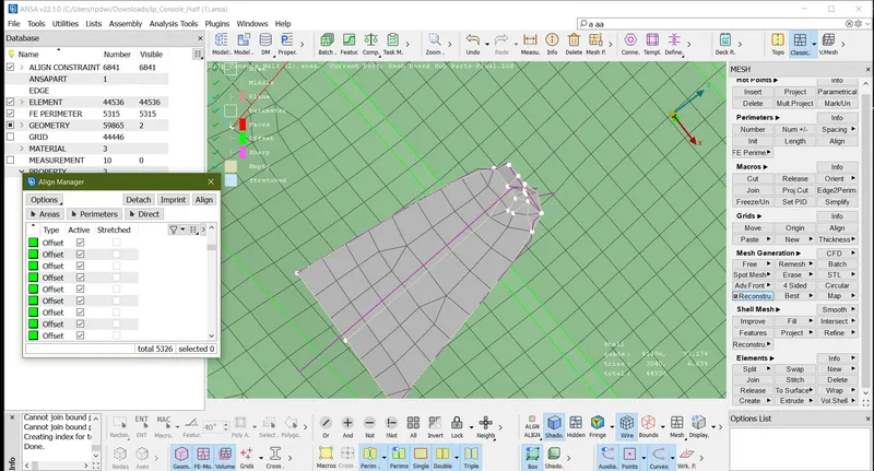
- Proper line projected and tongle unwanted line.
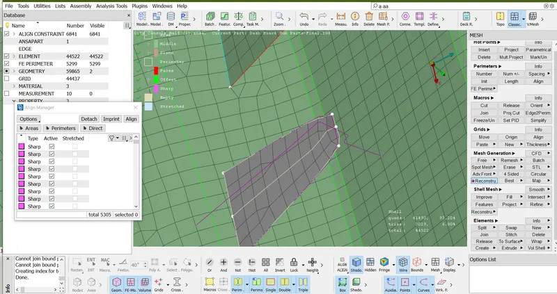
- Than create a surface (Classic>Shell mesh>Fill>Select the curve/Parameter>middle click of mouse)
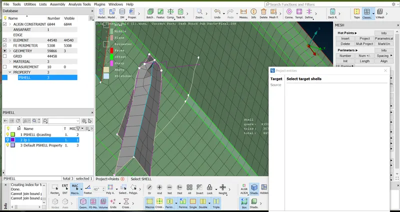
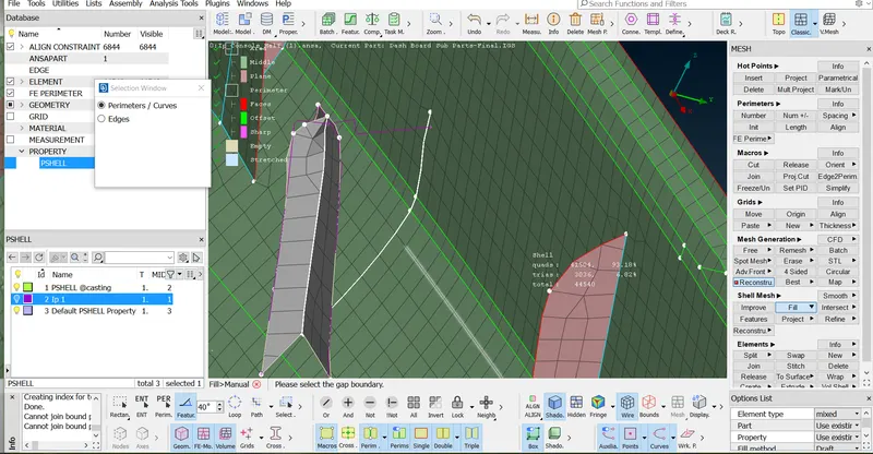
- Than create back rib surface By using (Classic>Shell mesh>Fill>Select the curve/Parameter>middle click of mouse)
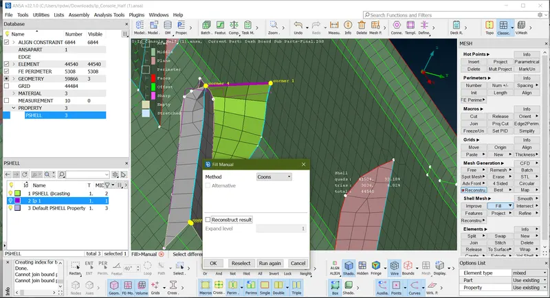
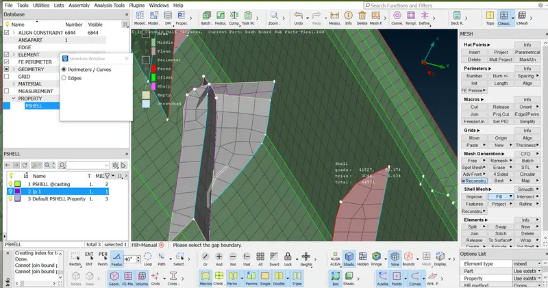
- Surface created and tongle all the unwanted line.
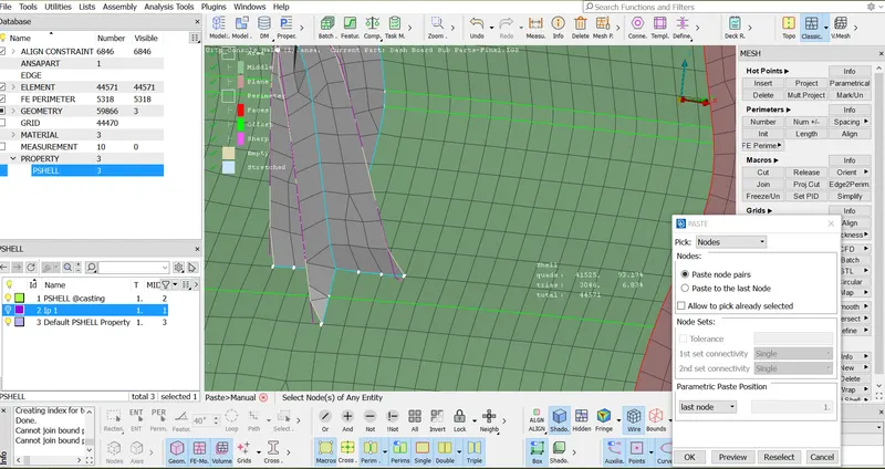
- When the dog house surface created but this dog house not attatched into base surface so first joint dog house by using Paste Option ((Clasic mesh>Grid>Paste>Select one node and second node>middle click of mouse)
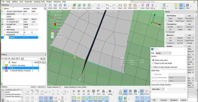
- Dog house attatched as showing below image.
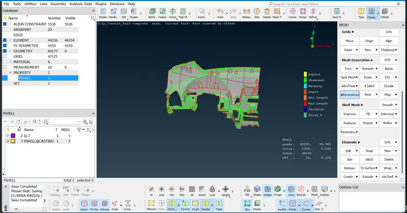
- Once the attatchment is done now assign these empty surface into a define Middle or plane accordingly.
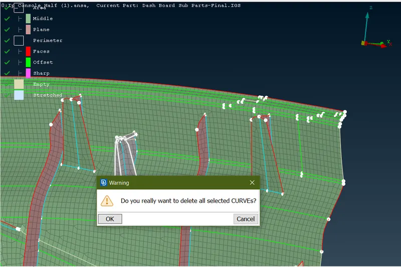
- or delete the curve by using (Topo>Curve>Delete)
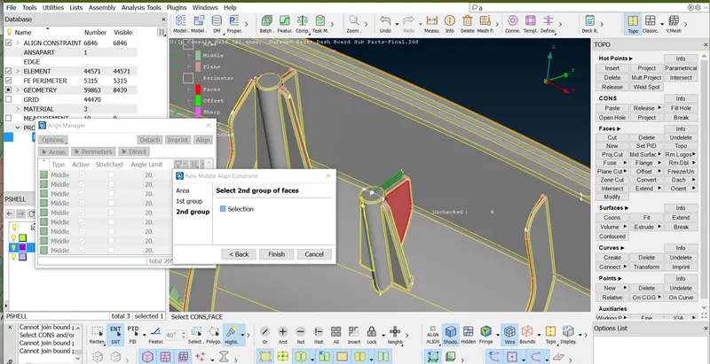
- Define Surface followingh stages
- Open align manager
- Select the Shell by macro.
- Right click of mouse on empty Area. anfd go to faces
- Select the red and blue surface as showing below image than finish.
- Area assign as showing below image.
- than assign every empty surface following same as above operation or align the constraints.
- similarly doing operation all the dog house and ribs.
-
- As below image this area not in a proper and part missing so first resolve this area by following stages.
- First tongle the unwanted line.
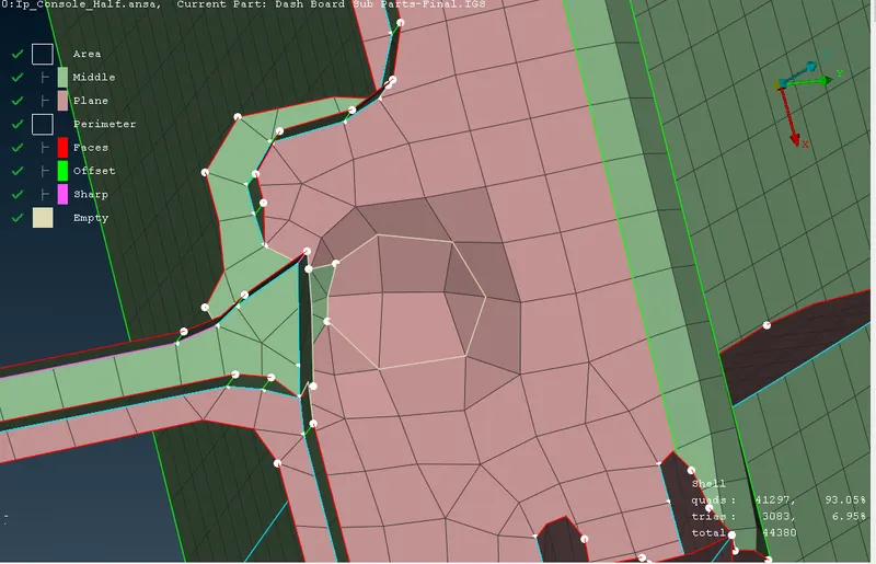
- Once the tongle the line Surface look like below image.
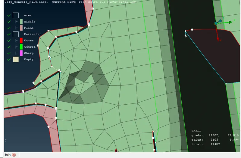
- Frist define this area as a middle by following stage's
- Open align manager Srelect the dented surface
- Pop-up this surface into a align mnanager or highlite tyhe arer where this surface exist.
- Right click middle area.
- Go to Edit
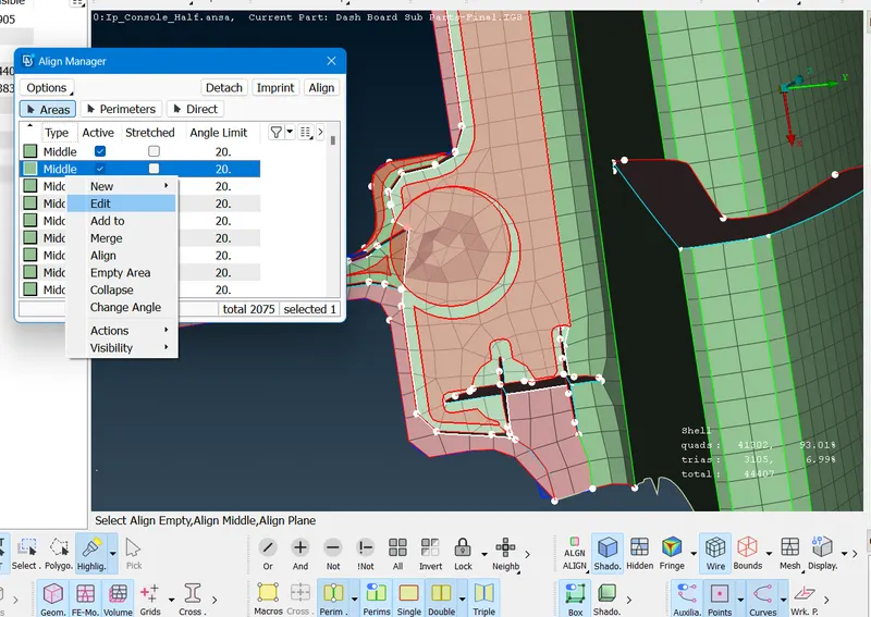
- Select red surface
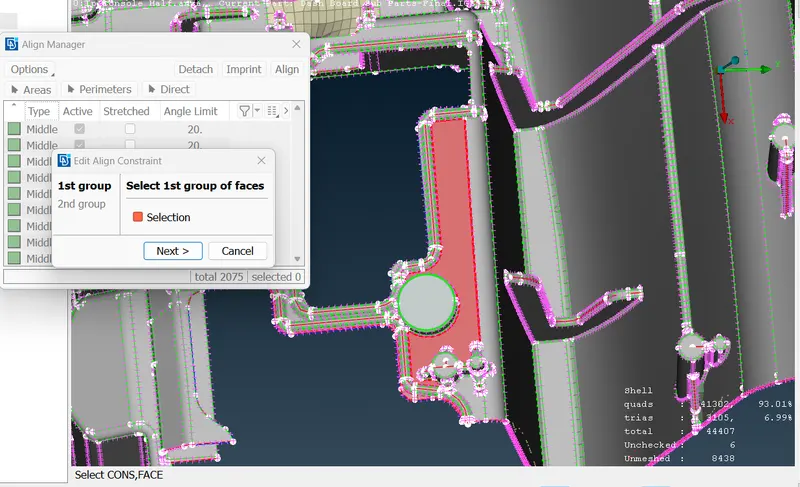
Select the blue surface.
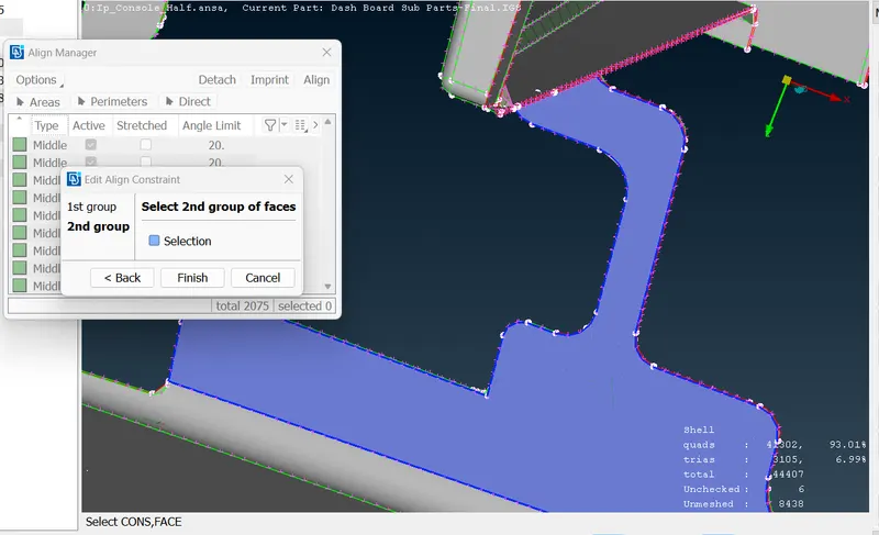
- Surface Flate As showeing below image.
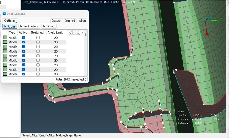
- Reconstract this area.
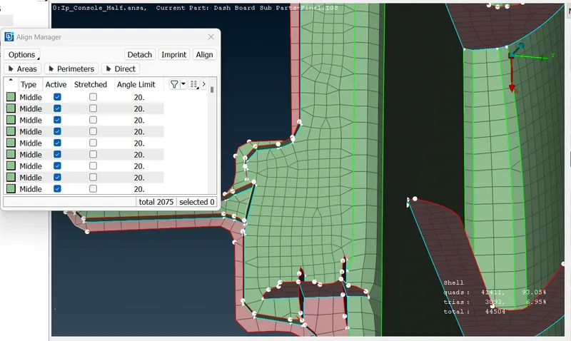
- Once the base surface achive flate than create cross surface by using below stage's
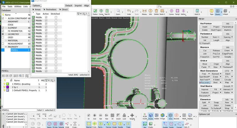
- To create the surface first by using (Topo>Curve>Create)
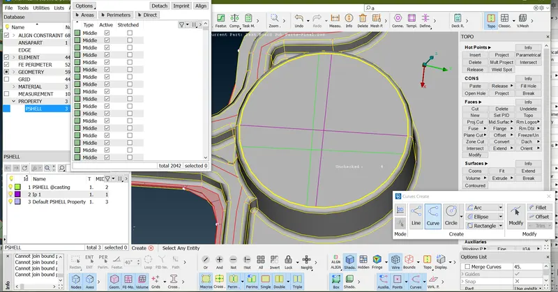
- Prtoject the curve line in base surface (Classic>Shell mesh >Project>select the Shells by macro >Next)
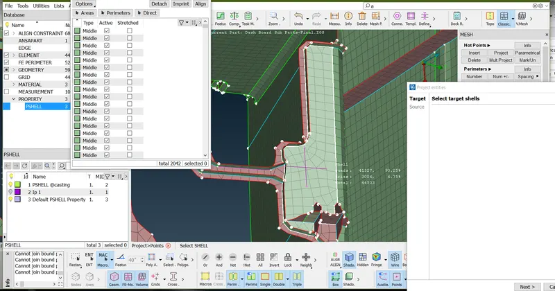
- Line projected
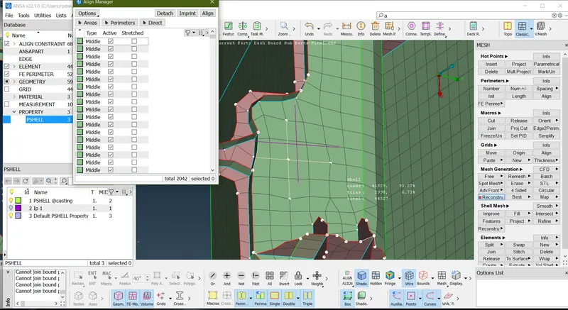
- To create the surface by using (Classic>Shell mesh>Fill>Select the curve/Parameter>middle click of mouse)
- To Attatchment this surfce into the base surface by using (Clasic mesh>Grid>Paste>Select one node and second node>middle click of mouse)
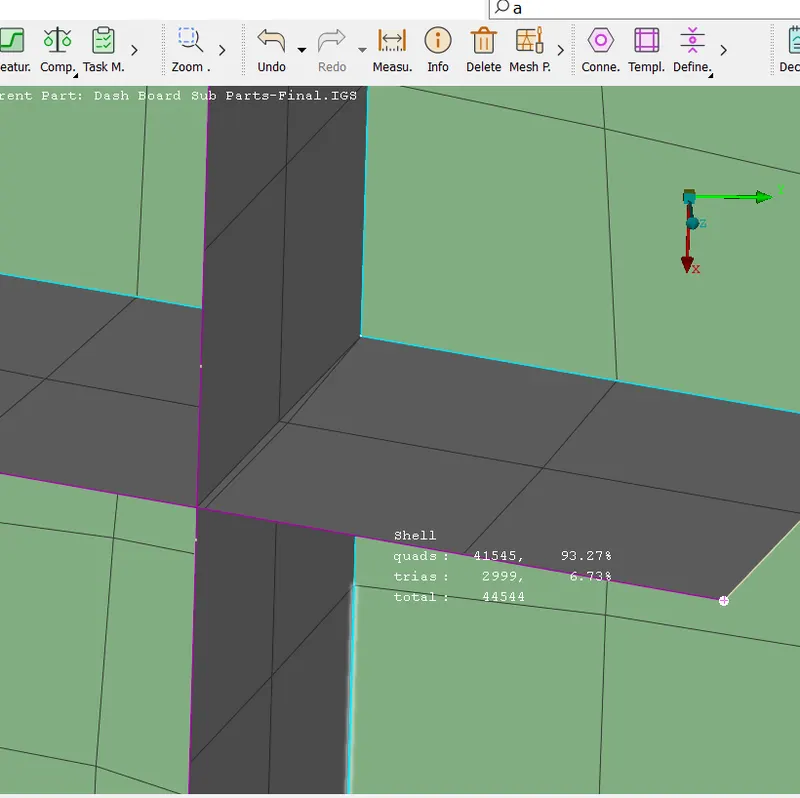
- As above image intersect two surface by using paste option.
- intersect surface as below image.
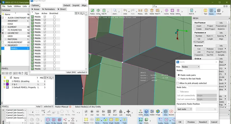
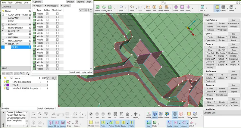
- Define this empty surface into a plane area by using Align manager>Add to function.
- final image of this surface and elemenate some trias as musch as can.
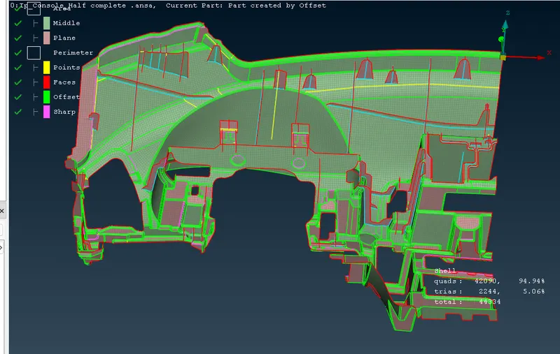
- Doing all the operation below is final image
- also elemenate all the empty area and parameter.
6) Assign Thickness to the Components:-
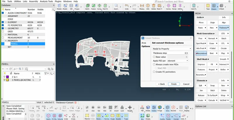
- Creating thickness by using (Classis >Grid's>Thickness>convertSelect all All the element>Finish)
7) Result -
- Generate mid-mesh by using casting method.
- Hence there are no surface deformations in the geometry.
- A well connectivity has been established between the surfaces.
- The features have been captured properly.
- A good mesh flow have been achieved.
- Hence thickness have been assigned successfully to the component.
8) Learning Outcome and Conclusion -
In this project i came to know,
- how to genrate mid-mesh by using Casting
- How to perform geometry cleanup for complex geometry.
- how to define middle and plane
- How to create surface while using casting method.
- How to extract mid-mesh for Ribs an dog house.
- How to achive less tria concentration with proper mesh flow.
- How to clear failing elements from quality.
- How to assign thickness by Automatic method.
9) Final image:-
By Mid-Mesh
Note- These 56 off element which is not elemenate because these element is in corner region so compromise those area.
By thickness
"C:\Users\ponnu\OneDrive\Documents\ansa models\instrumental panel\Ip_Console_Half_Final_Meshed.ansa"