Week 3 - 2D meshing for Sheet metal
1.
Objective:
The objective of this project is to perform preprocessing i.e. geometry cleanup, mid surface extraction, and 2D shell meshing for the hood component of a car. After meshing, component thickness and material need to be assigned to the mesh. And the mesh should follow the following quality criteria,
| S.no. | Quality criteria | Value |
| 1 | Target/Average length | 5 |
| 2 | Minimum Length | 2 |
| 3 | Maximum Length | 7 |
| 4 | Aspect | 3 |
| 5 | Warpage | 15 |
| 6 | Skewness | 45 |
| 7 | Jacobian | 0.7 |
| 8 | Minimum Quad Angle | 45 |
| 9 | Maximum Quad Angle | 135 |
| 10 | Minimum Tria Angle | 30 |
| 11 | Maximum Tria Angle | 120 |
| 12 | Tria Percentage | 15 |
Procedure:
First, the hood model is imported into the ANSA. The hood model contains five individual components as shown below.
For the given Hood model, Take the mid surface for all the components after checking the geometrical errors and mesh the mid surface with the given element Quality criteria.
COMPUTER AIDED ENGINEERING (CAE)
Computer-aided engineering (CAE) is the use of computer software to simulate performance in order to improve product designs or assist in the resolution of engineering problems for a wide range of industries. This includes simulation, validation and optimization of products, processes, and manufacturing tools.
A typical CAE process comprises of preprocessing, solving, and postprocessing steps. In the preprocessing phase, engineers model
the geometry (or a system representation) and the physical properties of the design, as well as the environment in the form of applied loads or constraints. Next, the model is solved using an appropriate mathematical formulation of the underlying physics. In the post-processing phase, the results are presented to the engineer for review.
1.HOW TO OPEN FILE IN ANSA:
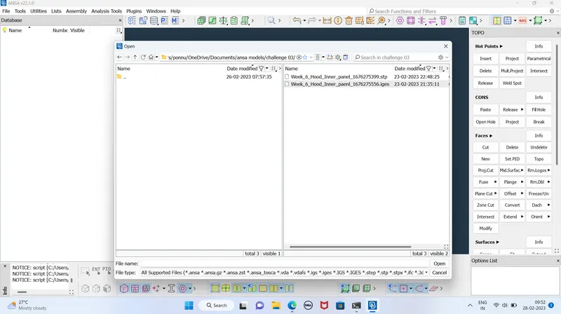
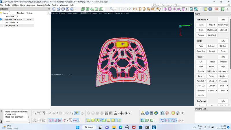
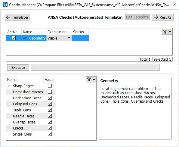
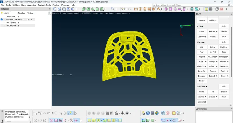
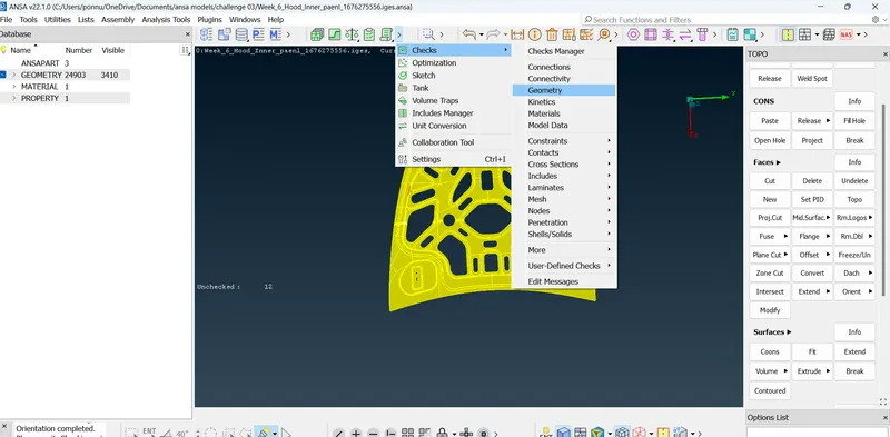
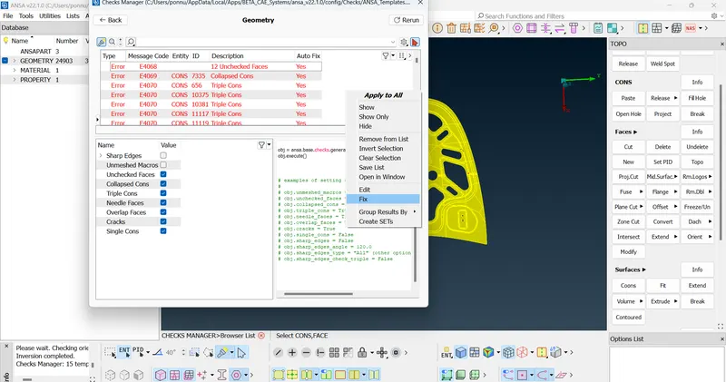
The first step after importing the model is to properly analyze and understand the geometry. When a CAD model is imported into the ANSA, there might be several geometrical errors like missing/distorted surfaces, intersecting surfaces, etc. due to the format conversion process or inherent bad model. And, it is important to clear all these errors before starting meshing. So, the next step is to clean up the geometry. To ensure that all the surfaces are connected properly Faces>Topo tool is used for all the edges of each individual component at a time. Next, geometry check is performed by going to Checks>Geometry and running it for parameters as shown in the image below. Another image shows the errors detected.
2.MAKE TO CONS RESOLUTIONS:
- Open the hood model from the files and it must be carried out for several operations .
- Check the geometry of the model from the 'checks' and execute the operation by selecting required check parameters .
- Fix the geometry manualy or by means of auto fix (geometry clean up ) .
We are provide with a hood containing 5 properties or components.
- After geometric clean up , we have to perform 'MID SURFACING' for each property .
- Mid surfacing can be done manualy by offset method or automaticaly .
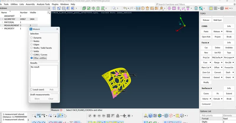
- Measure the thickness of the component by measure command .
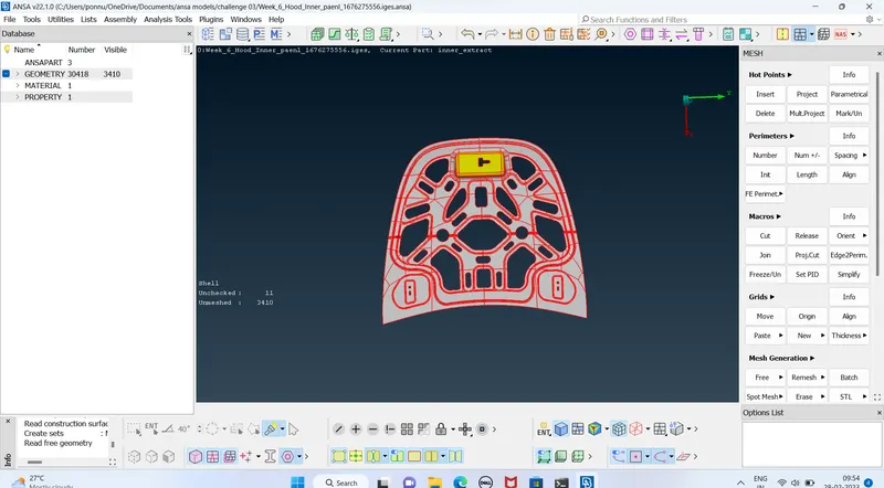
3. TO CHECK CONNECTIVITY OF SURFACES.
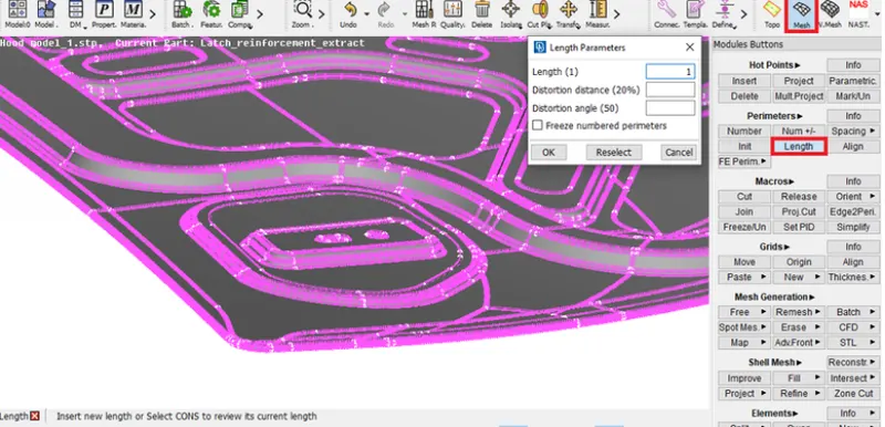
Initially, the part will not have proper resolution so to ensure proper detailing and viewing, we can use the length option which can be accessed through the Mesh module. This tool works in creating a finer representation of the model based on how finely the length of the feature lines is broken up into. All the surfaces need to be selected to use this tool.
4. TO CHECK THE GEOMENTRY.
The first step after importing the model is to properly analyze and understand the geometry. When a CAD model is imported into the ANSA, there might be several geometrical errors like missing/distorted surfaces, intersecting surfaces, etc. due to the format conversion process or inherent bad model. And, it is important to clear all these errors before starting meshing. So, the next step is to clean up the geometry. To ensure that all the surfaces are connected properly Faces>Topo tool is used for all the edges of each individual component at a time. Next, geometry check is performed by going to Checks>Geometry and running it for parameters as shown in the image below. Another image shows the errors detected.
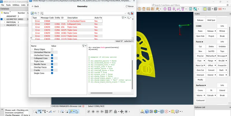
Select errors and give the FIX untill the errors will reduced..

5.TO CHECK THE THICKNESS THROUGHOUT EVERYWHERE THE SHEET,.
6. TO EXTRACT THE MID SURFACE BY USING THE MID SURFACE COMMAND.
Now, we shall generate the midsurface of each surface. This can be done using the 'midsurface' tool in the faces menu or using the 'offset' tool from the Topo module. The midsurface tool would be ideal here as the components have a constant thickness. The offset tool would be more effective in cases of varying thicknesses. For practice purposes, I went with the offset tool.
After selecting the offset tool, it will ask us to select the surfaces to offset. We can select the surfaces on one side of the component. After that, we can assign the offset value (half the thickness).
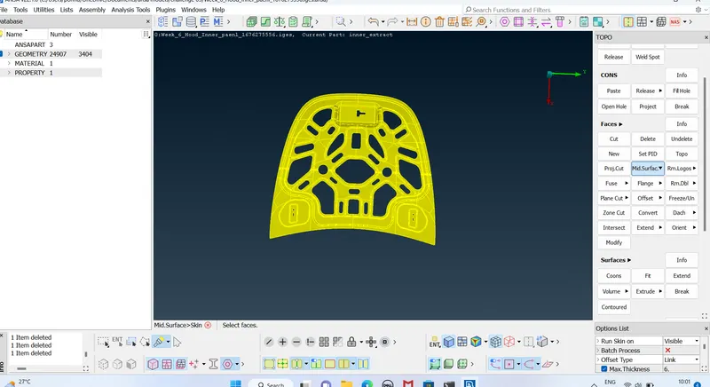
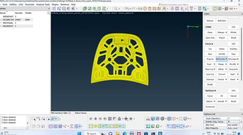 SELECT THE DELETE ORIGINAL FACES SWITH OFF,
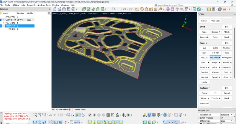
7.TO CHECK THE PROPERTY PID:
To keep the min surface and hide or switch off the parent surfaces.
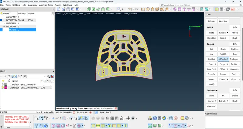
8. To give the quality createria:
Next, quality criteria are configured by going to Utilities>Quality Criteria. And, the quality criteria file is saved for future reference. The created quality criteria parameters are shown in the image below.
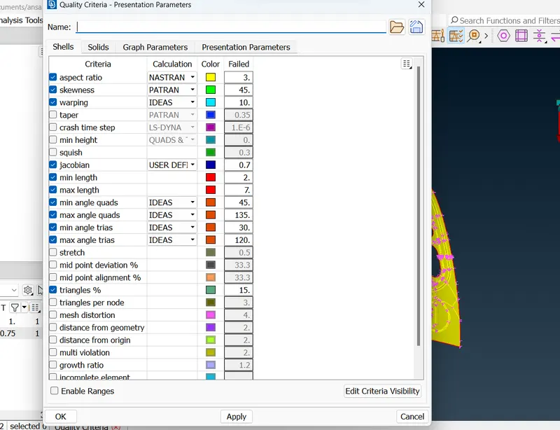
after that change the target length which given 5.
and min lenth 2, max length 7.
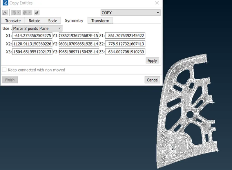
9.DIVIDE THE HALF DUE TO SYMMENTRY.
Due to the symmentry divide the half of surface into two and delete one half side mesh the half side as per the quality createria
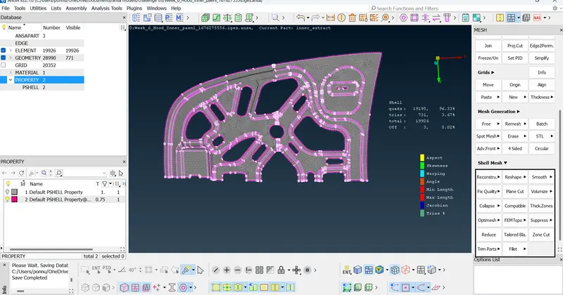
For generating the better mesh flow we have to avoid the Trias at the basis on;
- Avoid the trias which are forming opposite to each other.
- Avoid the trias,near fillet regions.
- Avoid the trias,near the circular holes.
- Avoid the trias,edges of the geometry.
- Avoid the trias,back to back trias.
Which will effect the results of the model and these can handled by some tools such as split(use in multiple ways are spilt,swap,join and dividing the quads),paste(use in movement of backward direction of trias).
Finally you will see the top surface of the latch part is left with free edges forming.
These free edges (Red Cons) can be converted to Double Con (Yellow Cons) by carrying out a Faces > Topo operation.
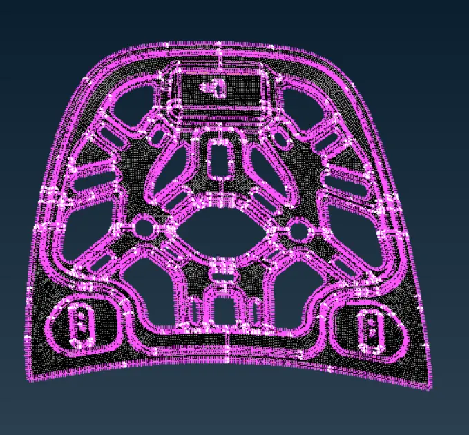
Here we can property of a inner component, Drawing styles > Select the Drawing mode tool bar , were we can find pid option and set the pid mode and click on it.
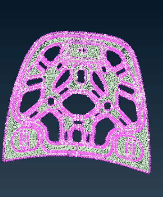
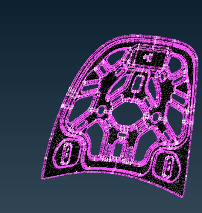
CONCLUSION;
- Before the performing the mesh on the model component, first model should ready with all topological cleanups.
- In order to acheive good mesh, remove the trias at edges, opposite trias, back to back trais, trias at the circular sections and fillet regions need to avoided.
- Use smooth option, for smoothing the mesh in an uniform manner.
- Mesh should passes all the Quality criteria parameters.
- Meshing the symmetrical axis of the compenets, saves a lot time.