Project 2 - 2D meshing on the instrumental Panel
Aim:- Mesh the model using casting method and align the component using align manager.
Procedure:-
1. First do a geometry checkup of model. If any error occurs, then fix it.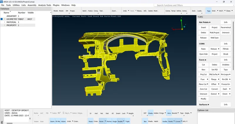
2. Then measure minimum thickness of model.
3. After that go to FACES, click on midsurface and select casting.
4. In casting parameter, enter minimum thickness, target element length. And in option enable 'handle as single solid'.
5. After that mesh is generated. Due to complex model, we need to use align manager tool for alignment of component to parent geometry.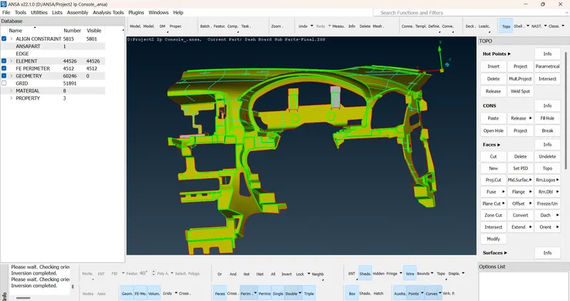
6. Improve base area:-
a] Go to align manager, select area tab then select required area. then right click on area type and select edit.
b] To edit align constraint, select 1st group of faces and then select 2nd group and hit middle click of mouse. Base area get aligned properly.
7. Alignment of fixtures i.e. dog houses and ribs
a] Delete the middle surface if necessarry.
b] Then create curve around the dog house using create option in CURVE.
c] After creating curve, go to classic mesh and select fill option in SHELL MESH.
d] After creating surface, use project option in SHELL MESH. Then select target shells and then select entities to project and click finish. Again go to fill and create surface.
8. After creating surfaces, connect the surface to base area as per parent geometry.
9. Provide reference to area.
a] To provide reference or defination to area right click in empty space in align manager window. Then click on new and select one option from middle, plan, offset, cylinder.
b] If middle is selected, select area then select 1st group and 2nd group of faces. and click finish. The reference is given to this area.
10. Provide reference to perimeter.
a] To provide reference to perimeter, right click in empty space under perimeter tab in align manager window. Then click on new and select 'faces' option.
b] Then select perimeter and then select face which reference to be given. Then click on finish. The defination is given to perimeter.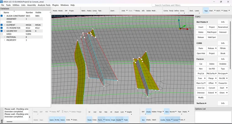
11. Then open quality criteria, enable criteria and click on apply. And then go to mesh parameters. Enter target length.
12. After that remove a off element using various commands i.e. Reconstruction, Smooth etc. Neglect the trias, rotating quads for better mesh flow.
Conclusion:-
Hence we use casting method for auto mesh generation on middle surface. And with align manager, align the components and elements according to parent geometry.