Project 2 - 2D meshing on the instrumental Panel
AIM:-
To Batch Mesh the given Casting Model of the IP panel for the given quality criteria’s without any failure in the elements.
Project description:-
The Casting Part:-
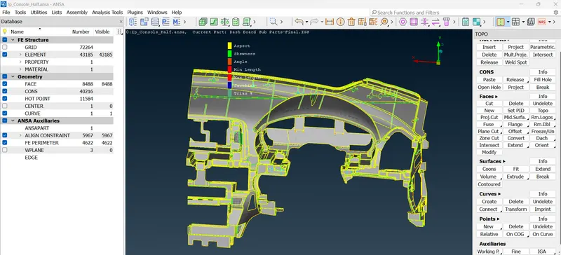
Procedures for Meshing a 2D component:-
Importing the CAD model into ANSA:-
The cad model is imported into the Ansa software.
Geometry Checks:-
Then the important step is to check the geometry of the CAD model. This will helps us to clear all the surface errors, unwanted cons and also for any disruptions placed in the CAD model. ANSA will check for the geometry and some of the errors will be thrown out by ANSA.
And hence all the CAD models were check for clean geometry and all their surface imperfections are fixed in the geometry check.
After that We need to give Topo to perform tropology.
Some of these errors can be automatically resolved by the ANSA by using the command Right click + Fix in the geometry check dialog box. After that we need to check all the faces some face we need to delete and recreate.
After when all these errors were fixed, the component is again checked for geometry and is fine to be cleared all the geometry checks.
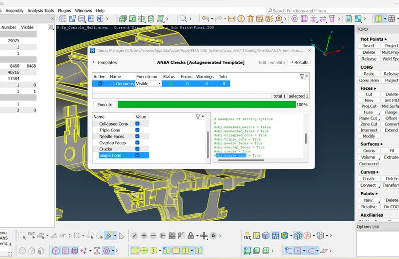
Geometry Cleanup
Before extracting the mid surface of the components, We need to check the Thickness , Based on the thickness we need to create the Mid Surface.
The mid surface is extracted using the Casting technique and the arears and perimeters were aligned using the Alight Manager tool if any discrepancies happen.
Fixing Quality criteria and Mesh parameters:-
Once the Mid surface is generated, the CAD model is now ready for the meshing.
The CAD model is now ready for the meshing. And for that the quality criteria for the mesh is defined using the command Utilities ---> Quality Criteria.
Then switch to 'Presentation parameters' tab , In Graphics division put tick mark for Elements% and choose the Details on demand effect as 'More details'
Then, select Utilities ---> Batch Mesh parameters and enter 3as the target length in the mesh parameters dialog box. The quality criteria dialog box will appear as follows and our given quality criteria’s are defined in the dialog box.
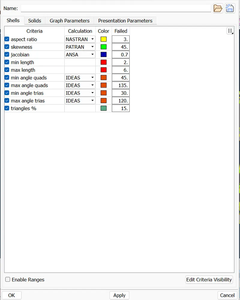
QUALITY PARAMETER
Then choose Perimeters ---> Length command and choose the entire component and give the target length of the mesh value as 3. (user can choose their own value). The same should be also done for the Macro to get a smooth surface before mesh.
. If we see any cons or hot points which will tends to fail the quality criteria, they can be suppress using Macros ---> Cut + Right click and Hotpoints ---> Delete options. Similarly, the minimum length error can be solved by taking peak value of the fillet and by suppressing the nearby cons.
Mid Surfacing:-
The mid surface of this component is removed using the casting procedure. Select Mid surface -> Casting. After loading the Batch mesh parameters and quality criteria, click on Run. The component's mid surface will now be extracted along with the FE
After all disfeaturing work is completed, the complicated component may be broken into batches to get a higher quality mesh, which can be accomplished using the Macros ---> Cut command, and then meshing can be performed to individual spots.
And Perimeter ---> Slide option is used to slide the holes in the component and make the perimeters almost parallel, to get an proper mesh in the component.
Finally choose Mesh Generation ---> Batch Mesh command and choose the faces to be meshed one by one like a flow.
And hence the Mesh will be generated in the component.
In the mesh, the following things should be observed:-
1) The mesh should be smooth and clean
2) Back to Back trias should be avoided
3) Tow opposite trias nearer to eachother should be avoided
4) Tria elements in the fillets should be avoided
5) Tria elements in adjacent to outer edges should be removed
6) Tria elements attached to the hole edges should be avoided
So, after obtaining the mesh, the above things to be taken care and the tria elements can be mostly avoided by using the following commands:-
Elements -> Split, Elements -> Swap, Grids -> Swap Paste These instructions are used to advance and reverse the trias, as well as to split them. ---> Elements The join command is also used to reshape several tria elements, and by employing these commands, we may accomplish the following requirements while avoiding the tria elements..
Shell mesh -> Reconstruct and Shell mesh -> Reconstruct Smooth commands are also employed in our meshed model to generate smooth parts.
And hence, when our meshes are failing to fill the quality criteria’s provided, they can be cleared with the help of the above steps and commands provided.
Align Manager:-
Then the Mid surface need to Align manager is used to match the areas and perimeters which were came out of their original mid surface.
And Faces needs Edit is used to sort out some of the Uno referable condition.
MESHED COMPONENT:-
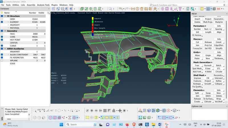
RESULT :-
The Mid surface extraction, meshed & Quality Criteria checked has been created of the given component.