Project 2
ELECTRIC PROPULSION SYSTEM MODELING
*For performance and fuel consumption simulation electric motor is modeled using the rotating inertia of the rotor.
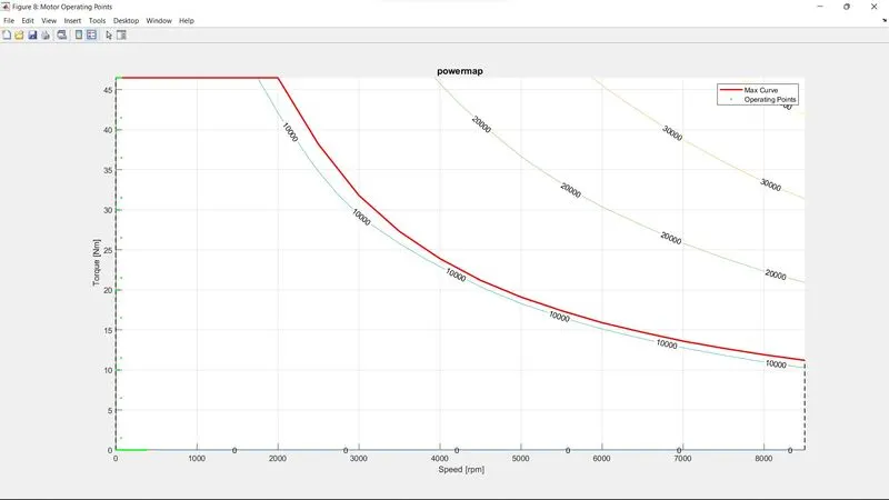
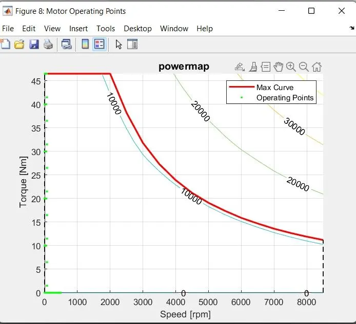
*The output torque in motoring and generating mode is limited by the max torque speed curve along with consideration for the time limit for the peak torques .
*Energy loss in the process is computed using the efficiency data for the machine.
*Actual torque is assumed to be instantaneous due to negligible time constant for an electric machine.
*Generally the electric drive power electronic efficiency is combined with the electric machine efficiency.
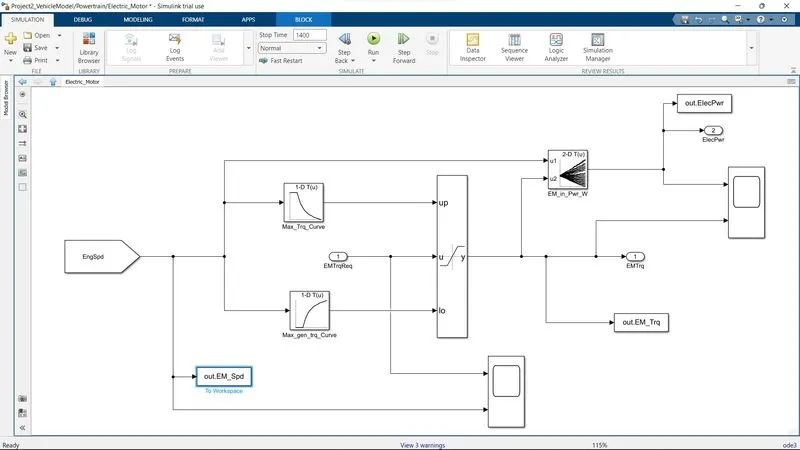
ELECTRIC MOTOR
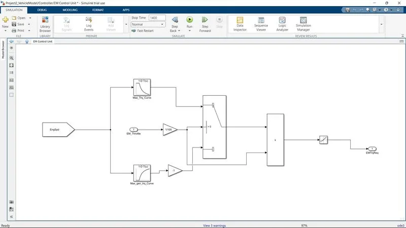
ELECTRIC MOTOR CONTROL UNIT
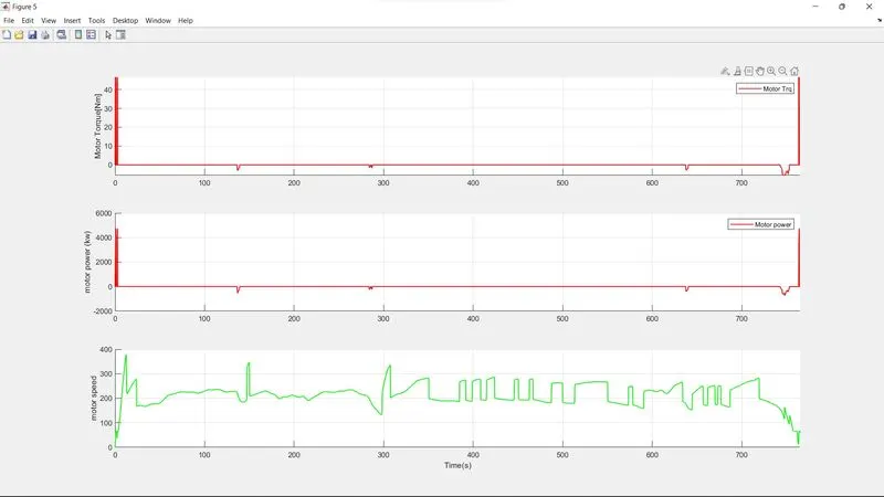
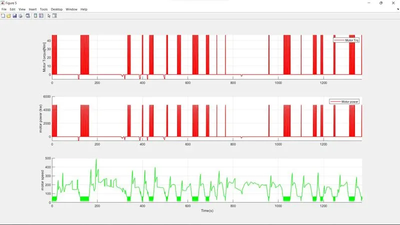
here speed come from engine goto block, to which electric motor connected. we modelling simulink of vehicle based on P1 hybrid architecture ,where EM connnected to engine . the speed block is come from goto block from engine. as a speed input it does not matter where EM located if it located before transmission its input speed is output speed of transmission . Dependinding where motor is integrated we have speed input that goes into map . here we modelled max torque curve and max generation curve torque this basically model for saturation the torque so that motor work more than usually limited by these torque curve, this torque demand come from EM controller so that it commanding how much torque you demand then we have to saturation that take speed as input this saturation dynamic is enssures that torque would be remain in those limit that is output torque that coming from motor. then we modelling efficiency map powerloss for motor that takes in speed and then torque has input that gives electric power, so it tell us how much electric power required there takes difference as power losses and then it finnally gives how much electrical power is required for particular mechanical power as such operating condition. this should be precisie because it will be input for the battery . for max torque curve it specify how much torque required at such condition and max gen specify consumption of power having negative in nature which signifies how much it regenertate the energy. this is p1 model vehicle where aEM connected to engine in parallel so here engine torque and EM torque is combined and we will get crank torque just adding the two torque and further summation in the form of crank torque for control EM block we have EM controller unit. EM control unit has EM throttle as input. It is as similar as engine control unit but here boundary for thrattle is range from negative 100 to positive 100. Negative shows regenerative torque as usual in this case. here started function as EM speed as input which is bounded to some limited for max torque curve and negative torque curve and then there is throttle which is divided by 100 that we get scale 0 to 1 . the main working here is we just multiplying throttle and torque. if throttle is positive then it would be multiplying by max torque and when it is negative it will go through min torque being multiplyed before this there negative gain block which makes it positive. based on throttle request is below zero that is negative of fifty percent. and last we have rate limiter which limit the rate of dynamic signal this helps stability of model having changing in throttle It is not essential but for smoothing the simulink odel and trying to represent as much as real life scenario there is limiter provide to this block higher the rate slower the reaction and lower the rate fastning its function in form of smoothing the simulink model thatshow we modelling the EM and EMcontrol unit having purilly control of speed or we can say torque having providing limitation from max to min .
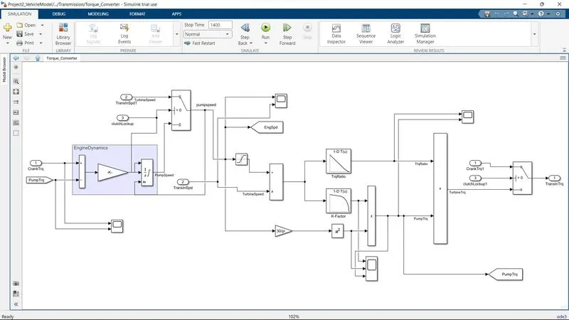
TORQUE CONVERTER
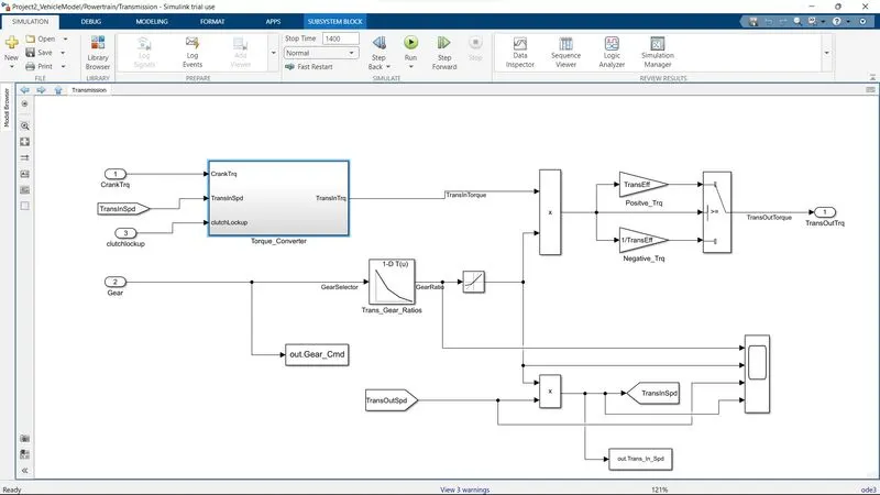
TRANSMISSION
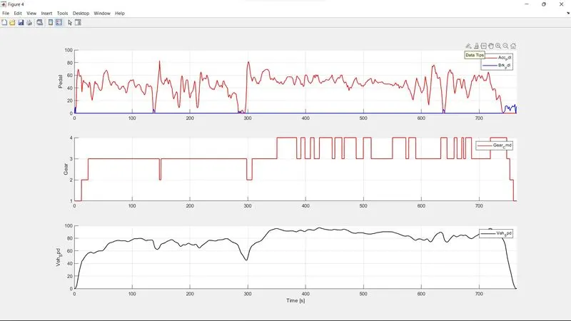
Here gear input feeds into 1-d lookup table that defines what gear ratio is depending upon what desired gear ia, output of this block is gear ratio that is goining transmission output speed block being multiplied and using this process what transmiision speed is. this result which we get using for other calculation. then this fed into torque converter block. the output of this block torque also multiplied by transmission gear ratio, depending whether it is positive or negative torque we just assuming constant transmission efficiency .And this efficiency get multiplied by transmission output torque. Other transmission torque get multiplied by transmission gear ratio to get desired output transmission torque The question is how input transmission torque we achieved is essential going torque converter block. So input torque converter block is engine torque which is due to engine connectivity and other is transmission speed, in this torque converter block there is input engine torque and pump torque having taking difference whichnis result of net torque acting engine inertia in this engine dynamic block that generates acceleration and then while integrating we get speed. For speed ratio we dividing pump speed by turbine speed. after this speed ratio fed into 1d lookup table and k-factor. here torque ration defining takes place .Here in k factor block there is no defining Kfactor because of having infinity output when speed ratio is 1 that needs to be divided what pump torque is, so we run into such issues so it is easier to find c factor ,the advantages of c-factor is that the value is low its inverse square of k-factor so we get inverse of infinity 0 for speed ratio 1. based on speed ratio it generates output c factor . here c factor define as pump torque divided by square of speed before this engine speed in convert into rpm and is multiplied by 1d lookup table that gives you pump torque and this pump toque fed into engine dynamic block and then it calculates engine speed to do all this we need initial speed. Thats how we get transmission torque so this how we modelling transmission
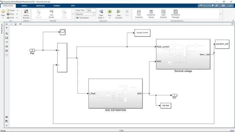
ESS
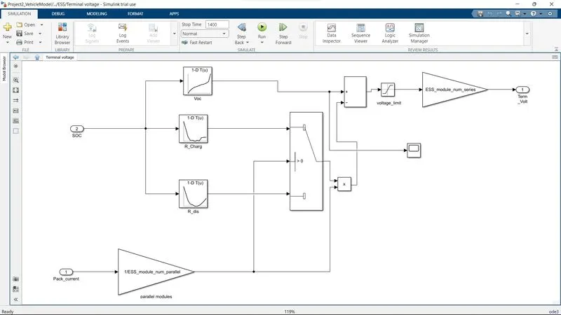
TRMINAL VOLTAGE
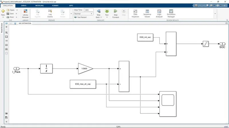
SOC ESTIMATION
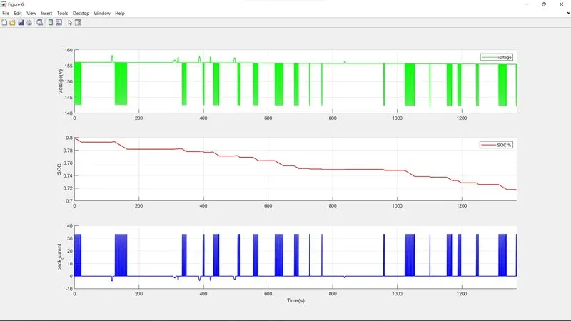
Input power come from motor , accessary , different auxillaryload those are summation of electrical power. for this model we only consider electric load from electric motor while accssary having constant 5 kw of load that can added to this power. there should be total electric power is coming from batteryeither it consumed or it will be regenerate that will happen when it is in charging. this power later divided by terminal voltage so the voltage battery can provide since power is voltage times current power divided by voltage we get current thats flow through battery that so called pack current
Now we have two different blocks terminal voltage block and SOC estimation. so in aSOC block the input is pack current thats going through the pack then based on pack capacity it will integrate the current and find what stste of charge would be and then next block is terminal voltage block this voltage help me to find the current that voltage is come from terminal voltage block where input is pack current and SOC applied equal sequence model basically it find what voltage circuite is and what internal resistance is current flowing through terminal voltage. the input of SOC block is pack current in ampere which rather then integrated to give in coulomb of current and then divided by 3600 to get back current in ampere. there is ESS MAX AH CAP which denotes maximum capacity of battery charge in that time we are divided integrated charge to get how much it is used divided by total capacity. Then we subtracted by initial state of charge .then there is saturation block from 0 to 1 to limit state of charge that should be not exceeding from its limit in this way we calculate SOC. In term of terminal voltage there is pack current as input modules are connected in parallel and other battery pack which is connected in series so for this we would find current passing through this module because voltage is same for parallel mode of pack,Achieving this we divided ess of parallel of charge by 1. Further we have discharge resistance and charge resistance and open cicuite voltage define intire module. in switch if value is positive then current is discharge and if negative then the current is charging. Having clearity of being charging and discharging this resistance multiplied by current functioning with ESS parallel module . the whole product we get in form of internal resistance. as we know that terminal voltage is (V-ir) .If current is positive then terminal voltage is lesser than Voc and when current is negative then terminal voltage is more than Voc. this is not total voltage we have given such limits from 9 to 6 and only between voltage limits then this will be multilplied by ess in series finally we terminal voltage for entire pack
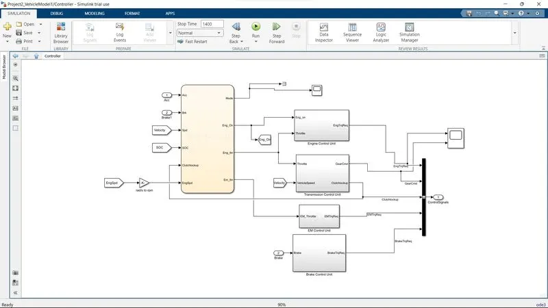
CONTROLLER
This is controller in which mode sellection block there is mode whish is connected to terminator and output signal to work space with scope having information about what is happening there. There are seven inputs to mode selection block .then it deciding which mode has to operating accordingly to controlling motor engine braking etc.
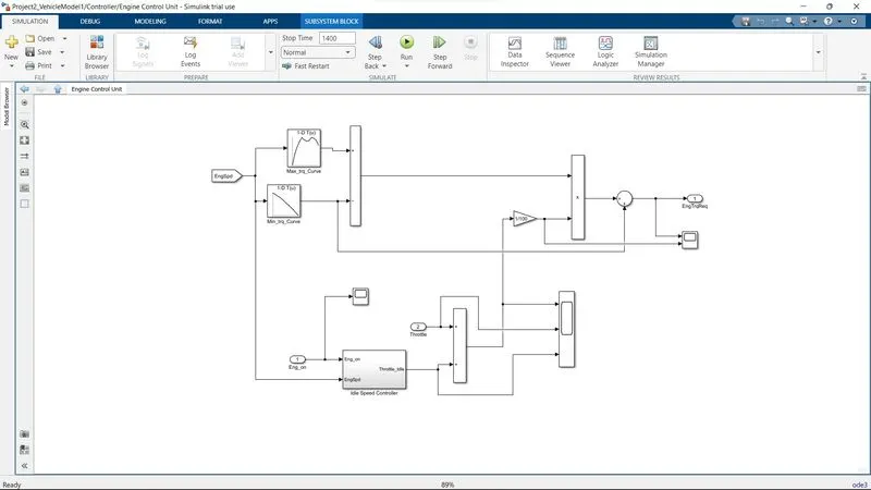
ENGINE CONTROL UNIT
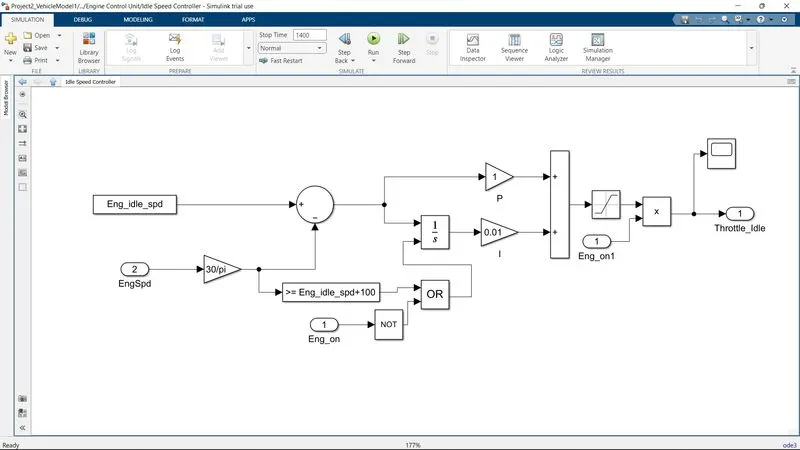
IDLE SPEED CONTROLLER
There is additional input in idle speed controller block engine on and off option ISC will disable when engine is off so when there is not required of providing torque request. As it move forward to functioning it will integrated having P and I signal to turn it into desired data summation of idle speed and output of the integrator this signal have to saturated in bounded length. So change in engine control unit remain the same as it before for other unit present there
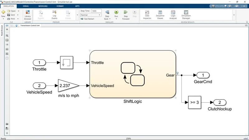
Shift Logic Block
In this block approx every thing is same having providing 3 gear for further connection to clutchlockup. third gear is working friendly because below this gear there is vibration so it is graeat hurdle efficiency . And this should not ignorable. less than 3 clutchlockup is open then there is no ndifference occur so that no torque passes through torus. at 1000 rpm at 1 st gear the pressure is low and lots of torque multiplication happening there is some error in clutch control
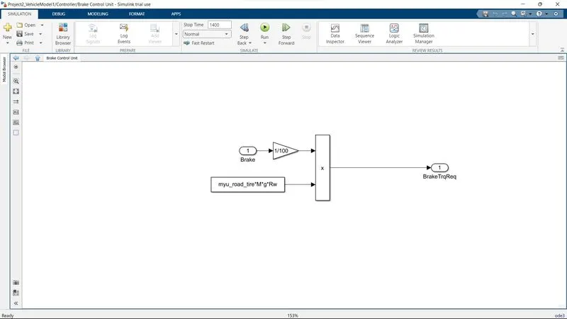
BRAKE CONTROL UNIT
when there regeneration braking there is need of friction brake there will not all of regen braking recover from Emotor. so it is finally shows that there is need of friction brake when it exceeding its limit.
ENGINE
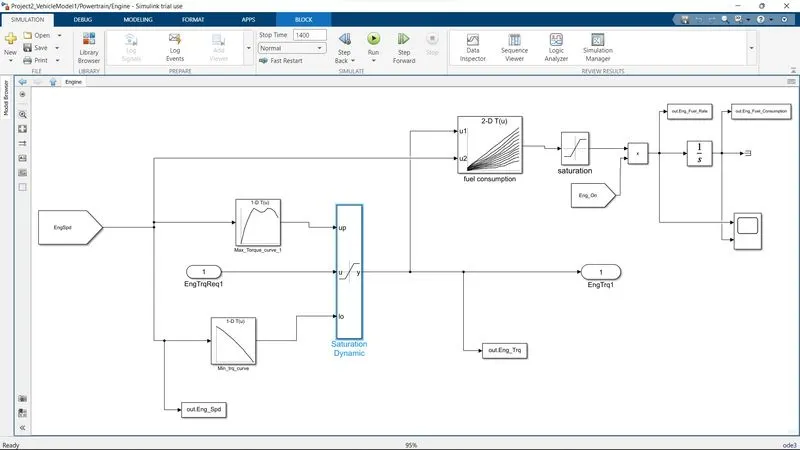
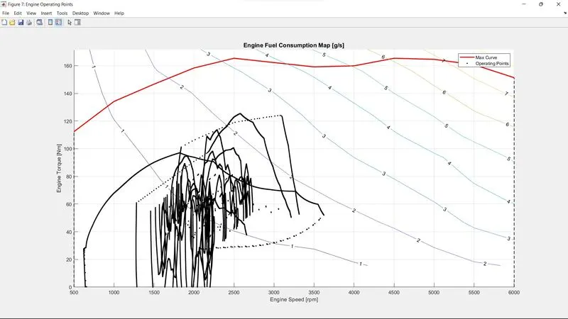
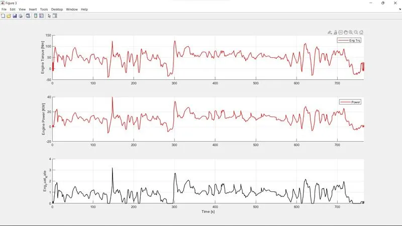
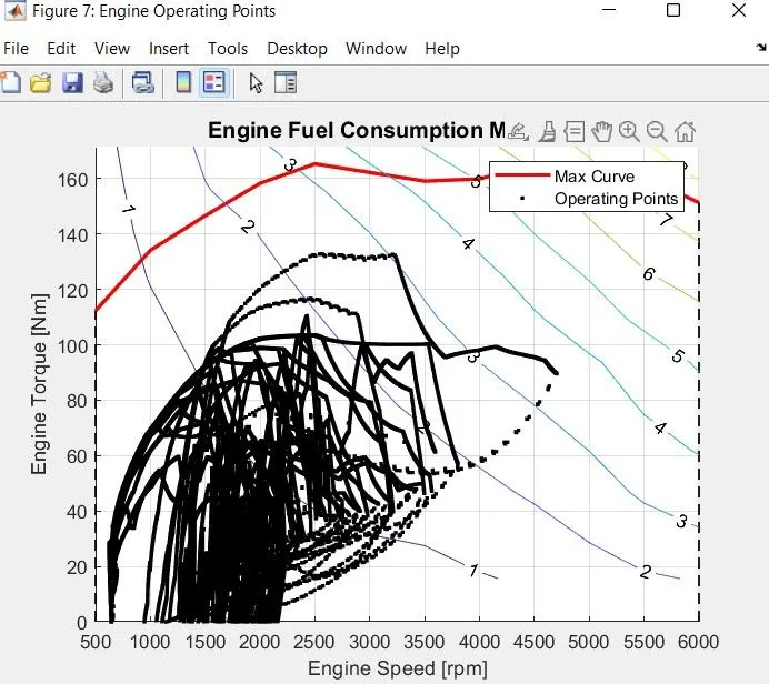
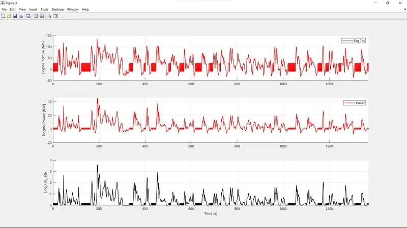
In engine block input to saturation dynamic as there engine speed fed into torque max curve and min torque curve having this working with together after limitation output torque we get in these bounded region. this torque and engine speed fed in 2d lookup table after this 2d lookup table this will be saturated with boundry applied region and multiplied by engine on so it get the information of having engine on and off and consumption of fuel is decreased in this condition.
CRANK HUB
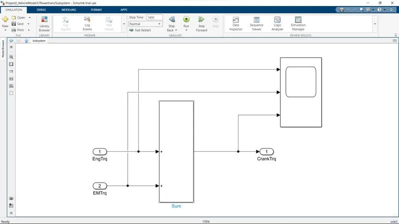
There is engine torque and electric motor torque as input to this crank hub. In this we have eng torque and electric motor torque as summation. So we get crank torque .as output . Here eng torque EM torque, Crank torque which were connected to scope so that there is checking of data what we get.
COMMENT
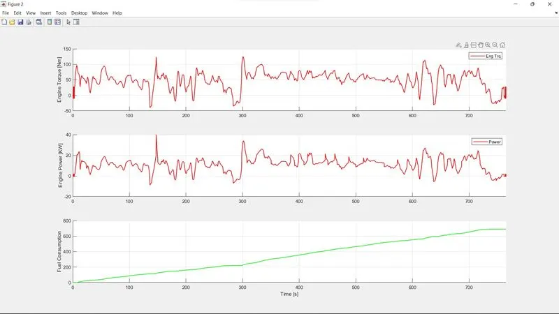
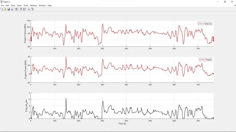
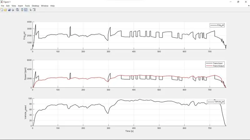
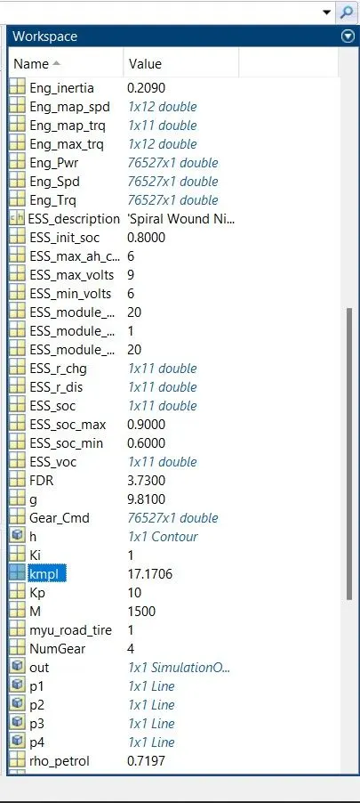
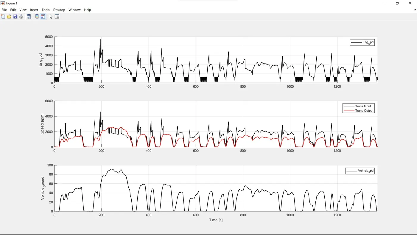
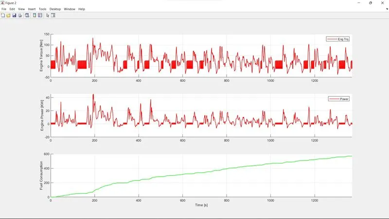
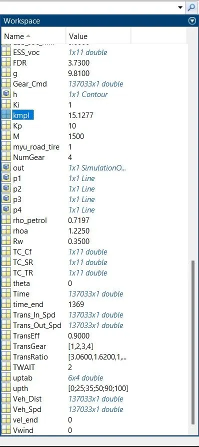
UDDS DRIVE KMPL = 17 KMPL.
HWFET DRIVE = 15 KMPL.