Project 2
FINAL MASTER PRODUCT
Step 1: Using the Class A provided the Tooling direction was made and both the Class A and Tooling Axis has been published.
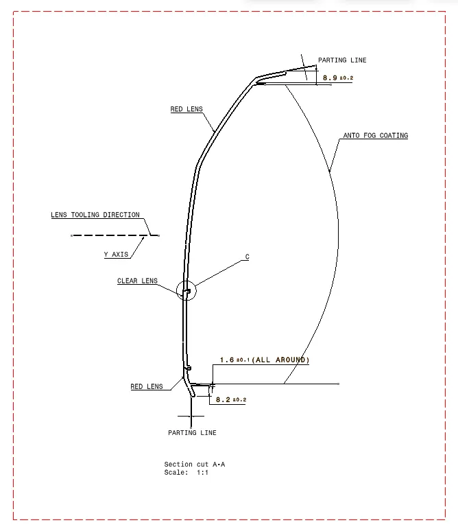
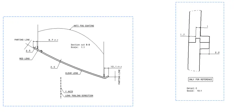
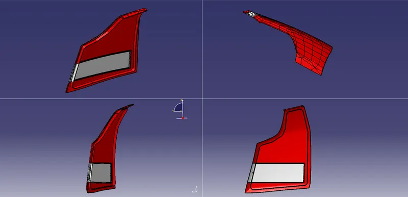
Step 2: Using the Class A, Class B Surface was created with option of Rough Offset as regular offset didn’t perform as expected. With the help of sweep and draft directions Class C surface is created and with the required split and Join operations we created a closed Surface Body with the appropriate dress-up features.
Step 3: With the Lens created the parting line of the lens is also made and is published.
Step 4: From the Lens we created we have to design a welding track for the lens. The welding track is created on the Lens Joining Part with the sweep and thickening tool. Then the welding track was provided with a draft of 1.5 degrees inward and union trimmed with the Lens that we created earlier and hence we got the Lens Body.
Step 5: Now we create the housing for the Welding Track with offsetting the Lens Centre Surface 1.5mm on both sides and also giving 1.5mm offset towards the welding track creating the Housing.
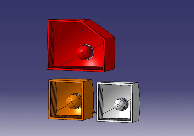
Step 5: Creating the Reflector surfaces with focal points for the Tail Stop, turn Indicator & Reverse Light made. Then the bulbs are positioned to the respective reflectors with the focal points created. A particular distance is maintained between the Focal points of the reflectors and the B surface of the Lens.
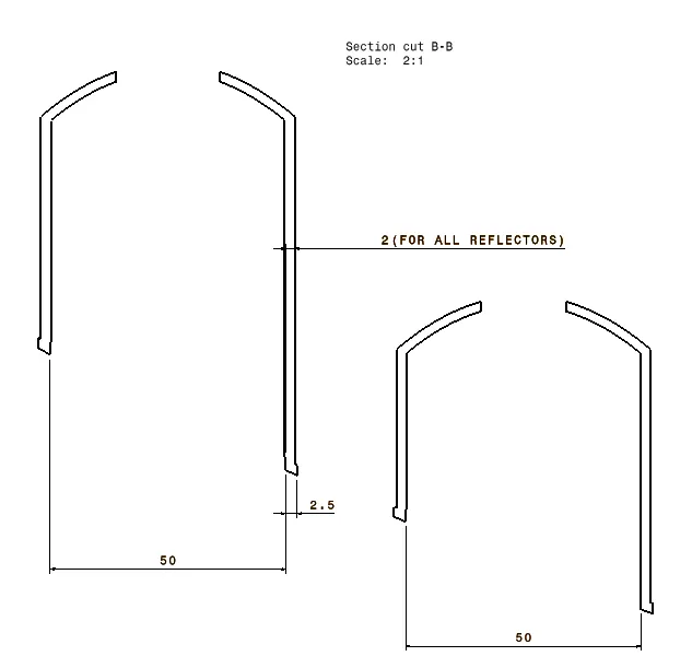
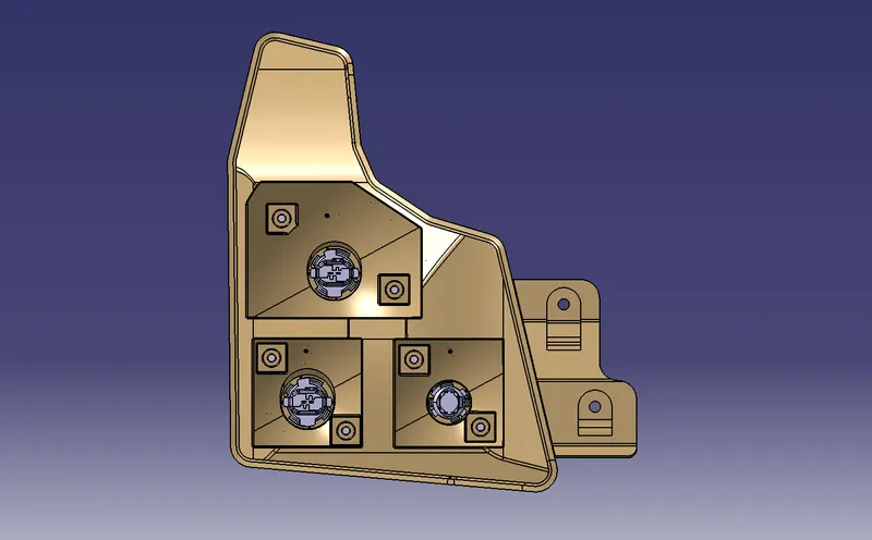
Step 6: The next step is to create the walls for the Reflectors to make it fit in the Lens. And you get the reflectors which then thickened about 2mm in a body. The housing for the reflectors are then created with an offset of 4mm from the inside wall of the reflectors.
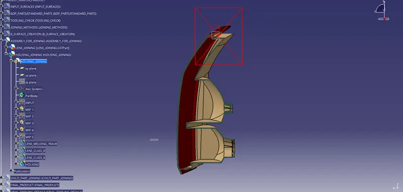
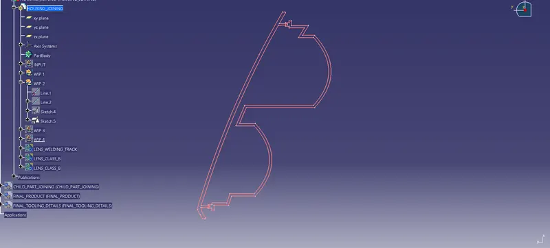
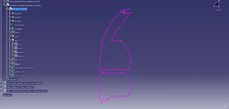
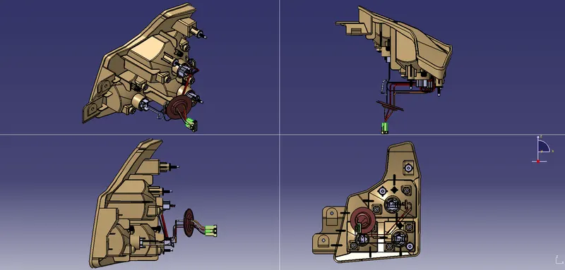
Step 7: In order to create the housing part we draw two sketches from the horizontal and vertical views giving 2mm thickness for the housing part to be made.
Step 8: With the sketches that we created we make the housing for the lens and the housing top welding area.
Step 9: Now we take the bulb seating areas and union trim it with the housing.
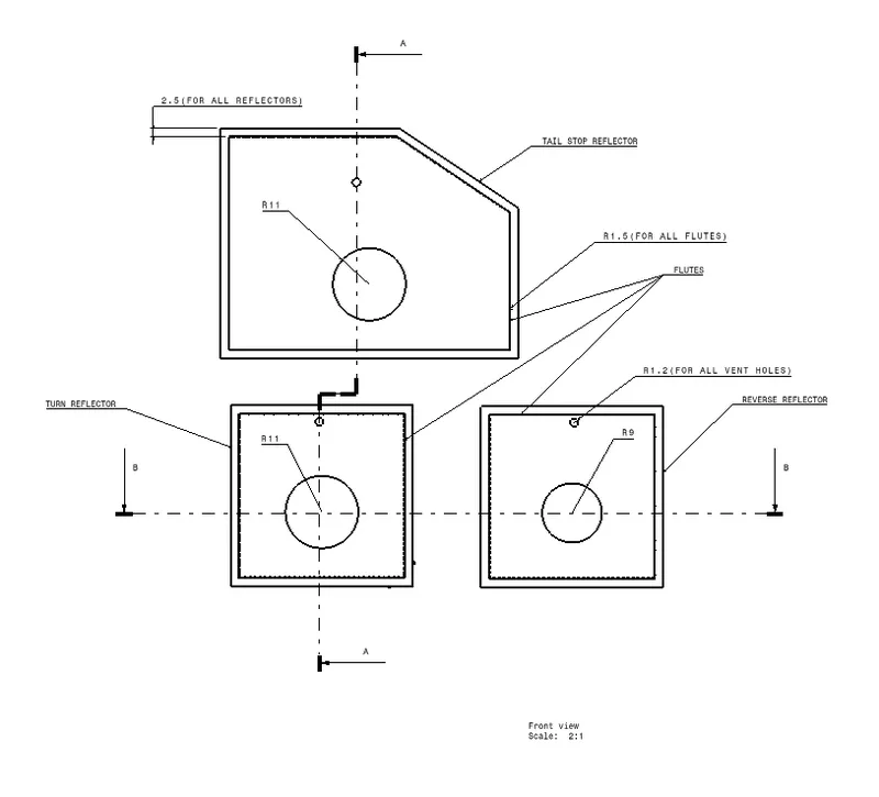
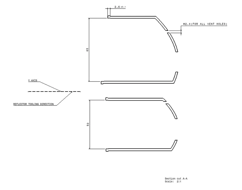
Step 10: We have to create the reflectors with respect to the Class A surface which is offset to 2.5mm and thickened to 2mm. This Thickened surface is split with new reflector offsets of 2.5mm and hence we get all reflectors which can be placed in the housing.
Step 10: A pair of M4 Screw Bosses are created on each of the reflectors. And along with it the Housing Boss for each of the M4 screws are also created and union trimmed with the Housing. The thickness of the Housing boss and the Housing are maintained at 2mm.
Step 11: Now we make the standards like the Stud and Stud Boss to fit into the housing and to restrict the 6 degrees of freedom via 3-2-1 Principle.
Step 12: A Dog House is created on top of the housing to arrest the 6 degrees of freedom and for the stud boss be at top of it.
Step 13: Now we create the flange for the housing with the drainage system in place with thickness same as that of the housing.
Step 14: The Nitto cap and the hole was created on to the housing and the reflectors respectively to provide ventilations.
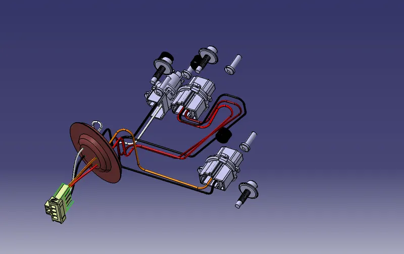
Step 15: Then we bring the connectors to make the wiring harness and to do that we have to create a grommet in order to attach the wires to the connector. The grommet is made with the help of the housing surroundings that we created. The wires are made for each bulb with the sweep command connecting them to the connector through the grommet. For the wires to beheld we also create a wire routing feature on the housing for support.
Step 16: Have to create the flutes for each of the reflectors on all sides with 1.5mm as the flute radius. Then we make the final inspection providing proper fillets on the housing part.
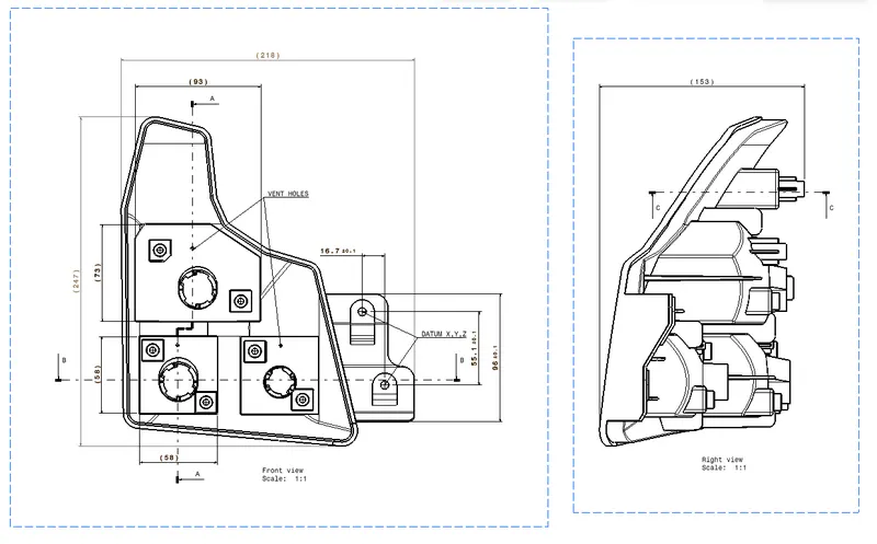
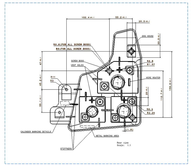
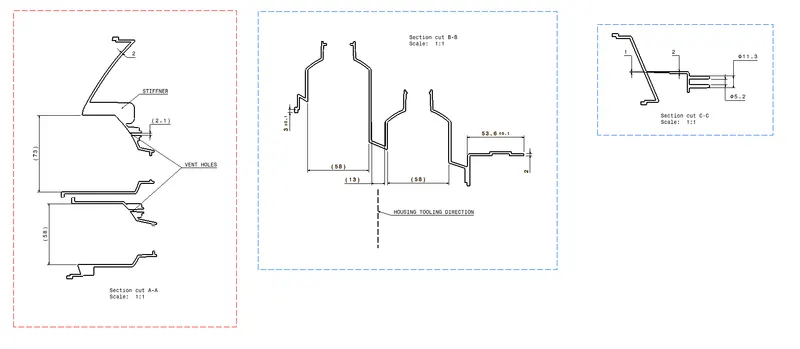
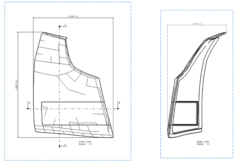
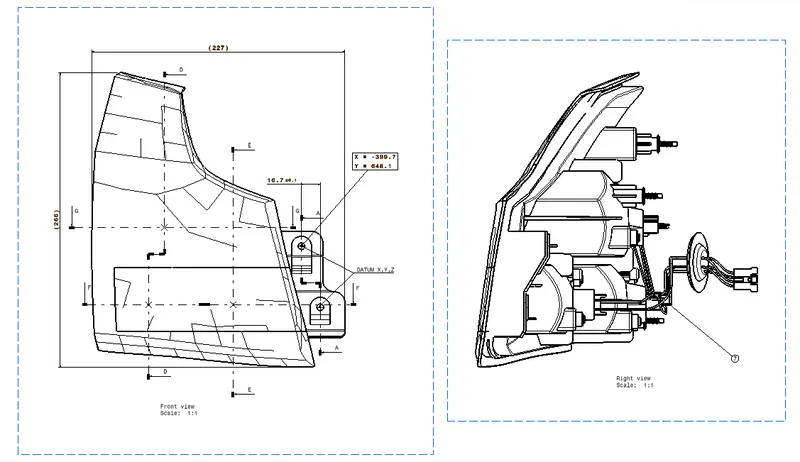
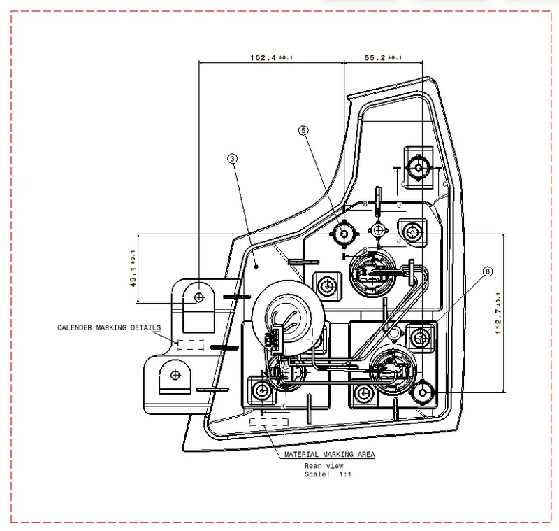
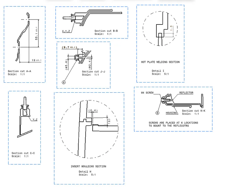
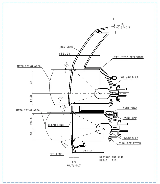
Step 17: Now the final step is to create the Assembly Drawing and the Child Part Drawing for the Product that we created.
- Technical Difficulties
Due to a bug in the software, couldn’t specify the coordinate systems in the assembly drawings for the fixation.
- SECTION VIEW
- SKETCHES
- TAIL LAMP
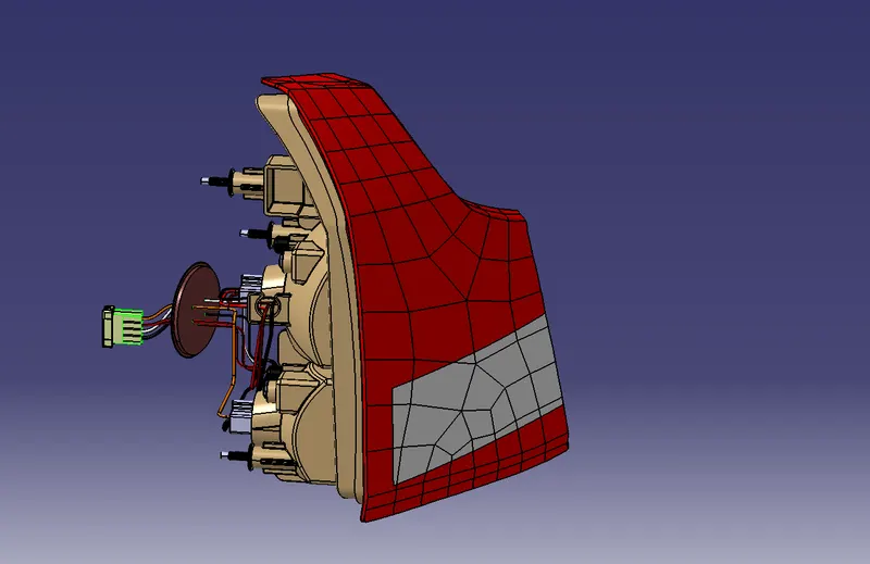
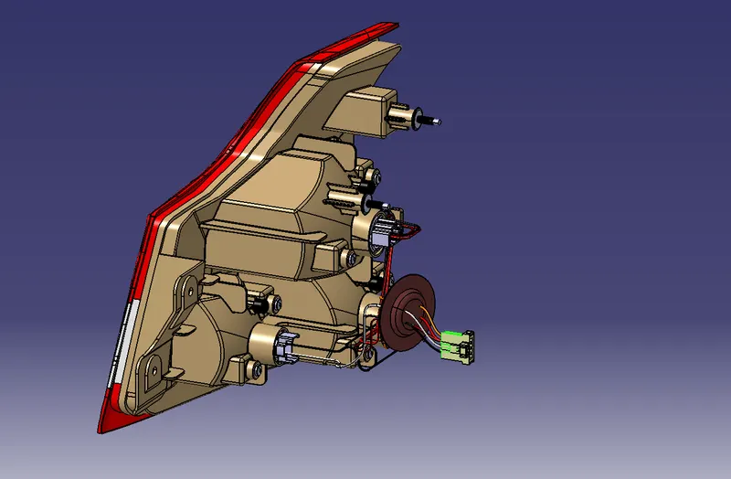
- LENS
- HOUSING
- WIRING HARNESS
- REFLECTORS
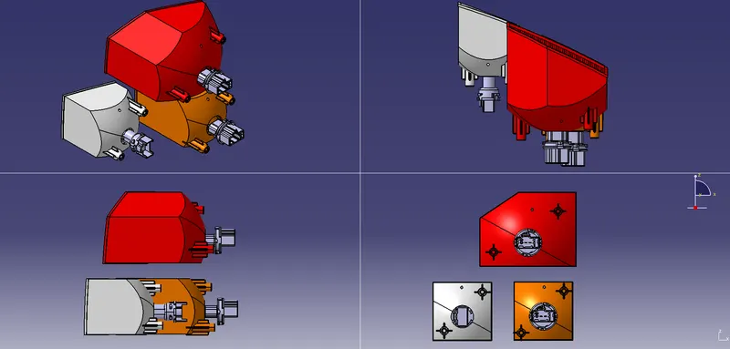
- ASSEMBLY DRAWINGS
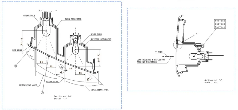
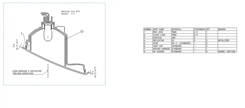
- CHILD PART DRAWINGS