PROJECT 2 - REAR SUSPENSION_MESHING AND CONNECTIONS.
OBJECTIVE:
To mesh the given CAD model of a rear suspension by following the quality criteria given in the data and performing connections using suitable conenctors.
Quality criteria:
Quality Criteria for Tria Elements (Tyre and Rim):
|
S.No |
Quality Criteria |
Value |
|
1 |
Target/Average length |
6.5 |
|
2 |
Minimum Length |
5 |
|
3 |
Maximum Length |
10 |
|
4 |
Skewness |
45 |
Quality criteria for Mixed elements (For Midsurface only):
|
S.No |
Quality Criteria |
Value |
|
1 |
Target/Average length |
4 |
|
2 |
Minimum Length |
2 |
|
3 |
Maximum Length |
6 |
|
4 |
Aspect |
3 |
|
5 |
Warpage |
15 |
|
6 |
Skewness |
45 |
|
7 |
Jacobian |
0.7 |
|
8 |
Minimum Quad Angle |
45 |
|
9 |
Maximum Quad Angle |
135 |
|
10 |
Minimum Tria Angle |
30 |
|
11 |
Maximum Tria Angle |
120 |
Quality criteria for Tria (For other components):
|
S.No |
Quality Criteria |
Value |
|
1 |
Target/Average length |
4 |
|
2 |
Minimum Length |
2 |
|
3 |
Maximum Length |
6 |
|
4 |
Skewness |
45 |
Common Quality Criteria for Tetra elements are:
|
S.No |
Quality Criteria |
Value |
|
1 |
Tet-collapse |
0.2 |
SUSPENSION SYSTEM
- Suspension is an arrangement of tires, tire air, springs, shock absorbers and linkages that connects a vehicle to its wheels and allows relative motion between the two. Suspension systems must support both road handling and ride quality, which are at odds with each other. The adjustment of suspensions involves finding the right understanding. It is important for the suspension to keep the road wheel in contact with the road surface as much as possible, because all the ground forces acting on the vehicle do so through the contact patches of the tires. The suspension also guards the vehicle itself and any belongings from damage and wear.
BASIC PARTS
- Control arm: A movable lever that fastens the steering knuckle to the vehicle's body or frame.
- Steering knuckle: Provides a spindle or bearing support for the wheel hub, bearing and wheel assembly.
- Ball joints: Swivel joints that allow control arm and steering knuckle to move up and down.
- Springs: Supports the weight of the vehicle, also permits the control arm and wheel to move up and down.
- Shock absorbers: Keeps the suspension from continuing to bounce after spring compression and extension.
- Control arm bushing: Sleeves that allow the control arm to swing up and down on the frame.
WORKING
The suspension control arms or links allow wheel movement independent of the body. This provides a mechanism to isolate body from the road bumps. The springs manipulate the frequency of road disturbances and try to bring them into a more manageable band. They also provide damping through friction (spring ends and the seat) and own hysteresis. The damper dissipates the energy of the dynamic load coming through the road bumps. Together, they try to eliminate the effects of road undulations on the ride as well as stability of the vehicle.
PROCEDURE:
Geometry cleanup
- A new .ansa file is opened and the .igs file of the given model is then imported on to the workpage.
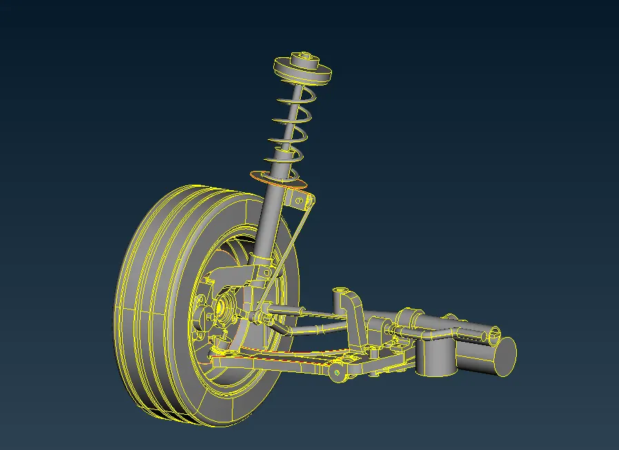
- Topology correction is done using Topology module>faces>top. This function automatically creates topological conditions between selected adjacent CONS.
- The model is then viewed in ENT( entity mode) from drawing style to check for any orientiation issues (Top portion should be gray and bottom to be yellow in colour) and if there is any issues its then corrected using Faces>Orient(tool)>visible.
- Turn on the Cross-hatches form Face draw so that surfaces can be selected easily.
- The pixel correction can be done using, Mesh module>Lenght (Perimeter=1, Macro=1). Its can be also done from Topo module using Auxillaries>fine.
- Each parts are then arranged to different property card using Faces>set PID.
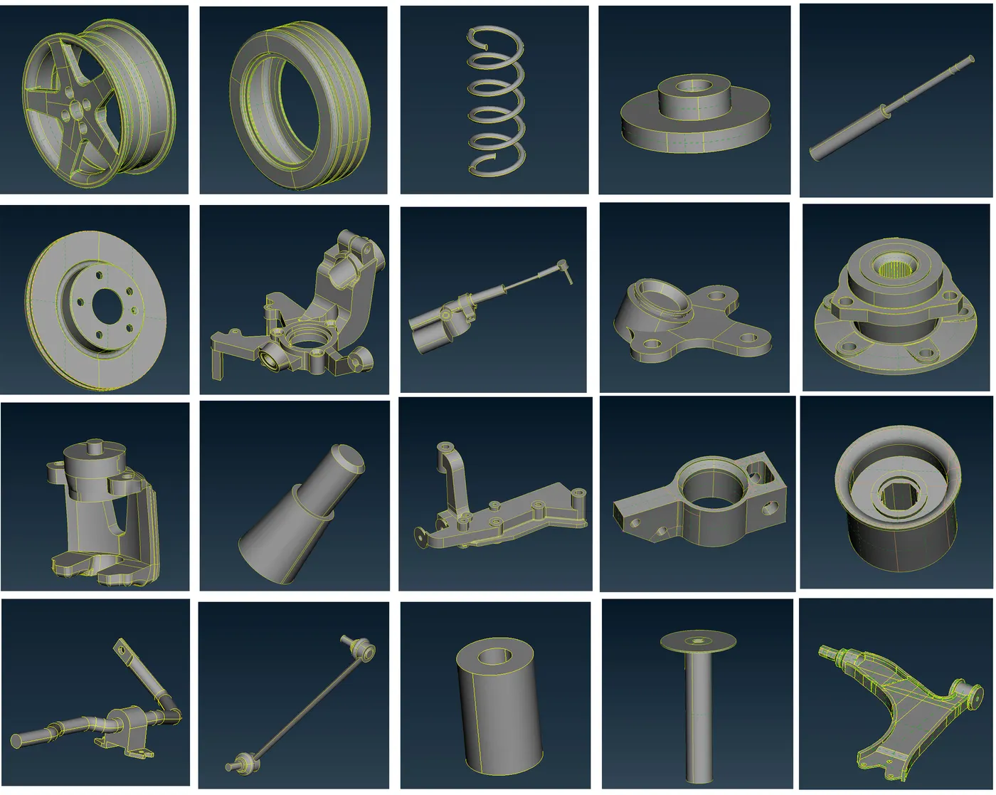
- Now each part is subjected to geometry check up to find out any missing surfaces, free edges, duplicates etc. Tools tab>Checks>geometry>Execute.
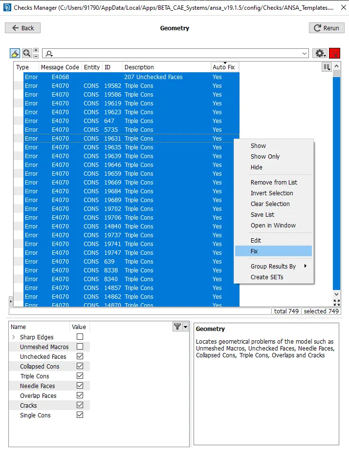
- When check up was carried out, Ansa throwed out error messages, in which some of them can be fixed automatically and others were done manually using other tools.
- After the cleanup the thickness of the model is been measured from different portions. If the measured thickness falls under 5mm for a particular part, The mid surface is extracted for that part and its been shell meshed using mixed elements. Rest of the parts are meshed using volume mesh.
- Mid-surface of the component is extracted using Faces>Offest.
- Splitting of the surfaces is done accordingly to avoid the failure of elements while meshing and also to get good flow over the mesh.
- These can be done using tools from topology and mesh modules. Join tool from mesh module can be used to toggle off unnecessary single cons.
- If the new surfaces were created using Faces>New>Existing surf, the cons drawn on the surfaces can be removed permanently by using Faces>cut (Right click).
- To check wheather the mid-surface is perfectly captured, The transparency is turned ON for the given model from the property card and then viewing the model in PID (property) mode. Shadow option from drawing mode is also turned on for the better visibility.
Meshing mid-surface using mixed elements.
- Meshing is done in mesh module and its turned on.

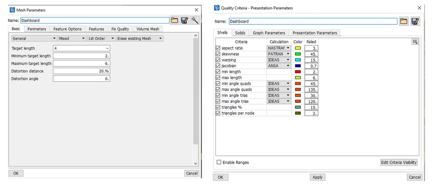
- The mesh parameter from untility is opened to enter the target element size, element type etc.
- Similarly the quality criteria option is also selected from the same toolbar and the values given as per the given data is then entered accordingly. From presentation parameter sub-option, check wheather the percentage element box is ticked also from detailed from demand effect drag the cursor towards all details.
- Along with the given quality criteria, Triangle per node is also turned on. (Two tria elements should not be connected to each other)
- Now each splitted surfaces are meshed seperately using Mesh generation>Batch or Best or spot mesh.
- While meshing its better to capture the surfaces with the given target element size for those in fillet regions it can be meshed with mininum element lenght.
- The surfaces can be again splitted to get good mesh flow using the cut option available in the mesh module and can be toggled after completing the meshing procedure.
- The hole areas can be aligned by controling the positions and number of nodes surrounding it using Mesh module>perimeter>slide or number.
- While meshing it resulted in creation of lots trias and rotational quads which can be again remeshed using Shell mesh> Reconstruct.
- Presence of trias in critical areas such as fillets, cut out regions are not preferable and it can be draged off using split, paste tool,swap etc.
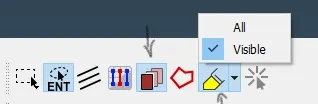
- Swich on the highlight tool to get the visibility while selecting points etc.
- While using split (Mesh module>elements>split), polygonal option from feature selection toolbar can be used to drag off tria to long distance. Show only, highlight option from the same toolbar is further used for the selection as per the need.
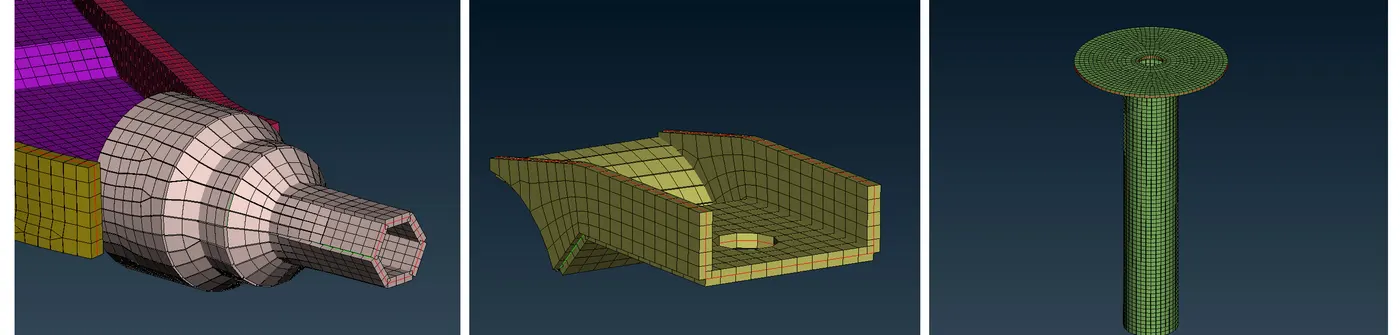
- The elements can be arranged uniformly using smooth tool from shell mesh option and while using this tool some of the elements gets displaced from the splitted lines and these can projected on to those line using Grids>origin. Node should lie properly on the surface, no deviation (No kinks).
- Quality criteria applied can be viewed using Hidden view> Drawing styles, Where the elements gets highlated in diferent colours indicating the failures to respective criteria and correction has to be made further.
- The thickness assigned to the model can be viewed using Utility>Quality criteria>Presentation parameter>Draw shell as solid.
Meshing the surfaces with tria elements and performing volume mesh.
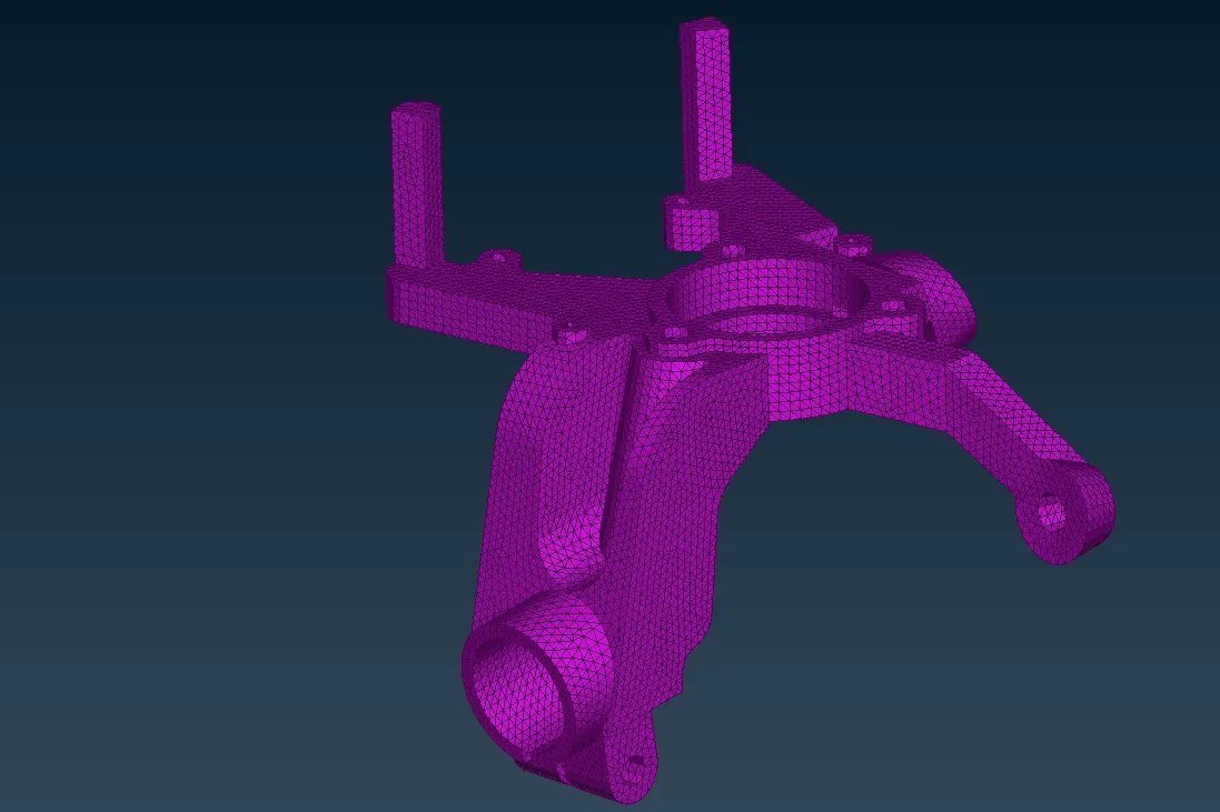
- Before doing volume mesh, all the surfaces of the parts are meshed with tia elements and then its been converted to volume mesh.
- Each part is taken seperately and meshed.
- Here also the given quality criteria and mesh parameter for tria elements was assigned and meshed as that of the above model.
- Normal trias and ortho tias are the element type used while meshing the surfaces.
- For the regions such as fillets, curved areas etc, ortho trias are prefferable and for plannar surfaces normal trias can be used. Even though ortho tria caputure the surfaces well as compared to normal trias, but takes more time for computation.
- For better mesh flow the region can be again remeshed using Shell mesh> Reconstruct.
- Paste, swap,split etc can aslo be further used to correct the mesh.
- The elements can be arranged uniformly using smooth tool from shell mesh option and while using this tool some of the elements gets displaced from the splitted lines and these can projected on to those line using Grids>origin.
- Quality criteria applied can be viewed using Hidden view> Drawing styles, Where the elements gets highlated in different colours indicating the failures to respective criteria and correction has to be made further.
- After the shell mesh and checking the quality criteria and ensuring the parts are fully closed, its been now taken for doing volume mesh.
- Volume mesh module is turned on.
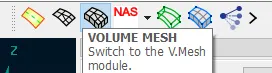
- Now we need to define the model as volumes for generating the volume mesh. Here seperate volume is been defined for each parts successively using Volume mesh module>define>manual>New>P-Solid.
- List option from volume will shows all the defined volumes and the tetra mesh is now performed on each defined volume by right clicking each volume>Remesh>Tetra Rapid or Tetra FEM.
- Once its completed the volume mesh can be viewed using the boolean operators or putting it in bounce mode. Also turn on the volume icon from the visibility tool bar.
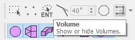
- Here the quality check is done only for the tet collapse.
Tet collapse
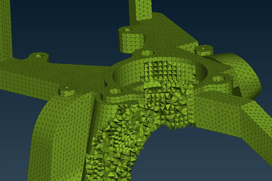
- Defect generated when the height of tetrahedron 3D element is less than the target element length. Tet collapse defects were cleared by re meshing the failed elements and changing the height of tetra element by translating nodes. Fix quality from volume mesh module and MV free tools from mesh module can be further used for this correction.
- Its should noted that, the final mesh should be free from peaks (element projecting outward) and kinks (element projecting inward).
Performing connections.
Representing torsional spring.
- Torsional spring can be modelled with hexa element or represented as CBAR or CBEAM. While modelling with hexa elements it takes more time for computation but it will give accurate results compared to other method.
- Here its been represented as a 1D element by using CBAR.
- To represent it as a 1D element the middle curve is been extracted from the CAD model (the curve should be connected) and the extrated curve data is been then converted to connection data using, Nastran deck>CBAR.
- The cross sectional area of the spring is also measured before and is assigned in the property card (use "Shift+?" in the area coloumn to assign radius). Here the specified element lenght is given as 4mm.
- To visualise this reprsentation go to mesh parameters>presentation parameters>line element cross section>as solids.

Representing Seam weld
- Seam welding is the joining of work pieces made of similar or dissimilar materials along a continuous seam.
- Its mainly used in structural load carrying areas because it provides more structural rigidity.
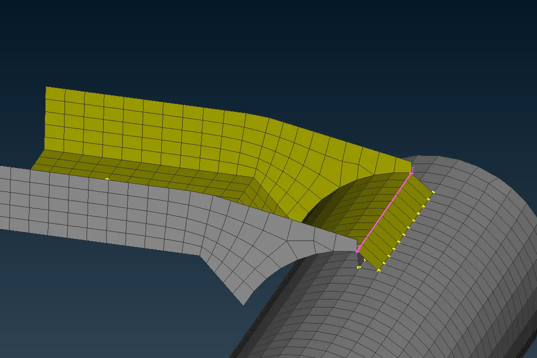
- For representing seam weld we need to create a curve data and then its been converted to seam line data using convert option in assembly toolbar. The curve data can be created using the curve tool or Feat2curve. The The seam line data can be realised from the connection manager. In the connection manager two parts are selected and the avarage thickness is assigned to the property card.
- Seam weld can be represented in two ways using shell elements as overlap shell and Y-Joint shell.
- Y-Joint shell is used when the two parts are parpendicular to each other and when the parts are parallel to each other then overlap shell is selected.
- After doing seam weld the mesh will get distorted and further correction has to done to have a good mesh flow.
Representing bolt connection
- Bolt connections are used to connects two or more holes either its shell or solid mesh. Also if there are two mating parts there is no seam weld in between then the parts are joined by bolts.
- If the hole is made up of more than four nodes providing the hole with a zone of element (washer) is preferable. If there is no washer present in meshed model, it can be formed using mesh module>shell mesh>zone cut.
- Bolts can be represented as a manual rigids and automated connection.
- When representing it as an manual rigids, RBE2 elements can be used. Nastran decks>Elements>RBE2.
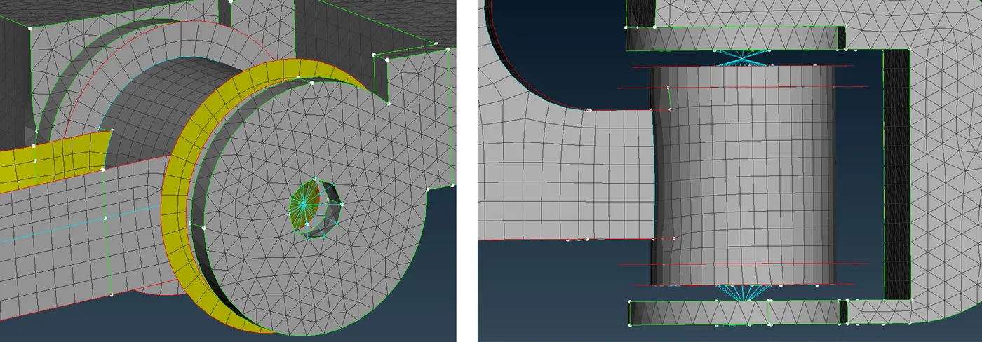
- RBE2 can be classified as single node and many node (cluster) RBE2 where there exists a master node and slave node in them. Based on the position and distance of the slave node Ansa identifies the COG of that hole and by default it will show the location for the master node.
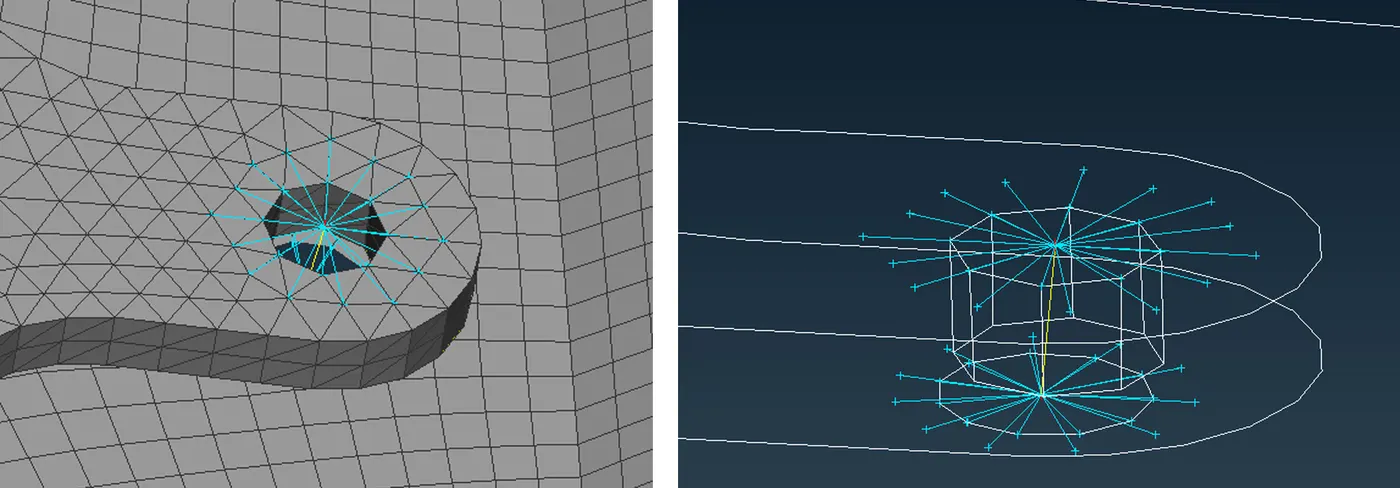
- The image below shows the creation of RBE2 element using many node (cluster).
- To connect two component by bolts using manual rigids, Many node RBE2 elements are created seperately for each hole and then the master nodes of the two hole is then connected using a two node RBE2. Thus a physical representation of bolt and nut can be achieved.
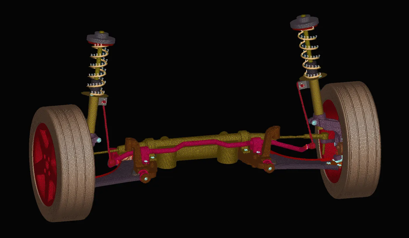
The conections to the remaining areas of the model is done using suitable connectors.

After completing all the connections all the entities are reflected to other side using transform option.
RESULT:
The given suspension CAD model has been meshed sucessfully by following all the element quality criteria given in the data and performed connections using Nastran deck.
LEARNING OUTCOMES:
- Geometry clean-up.
- Maunal mid-surfacing.
- Shell meshing with good mesh flow.
- More knowledge on quality criteria.
- Assigning thickness.
- Meshing solid components.
- Realising connections.
- Time management.