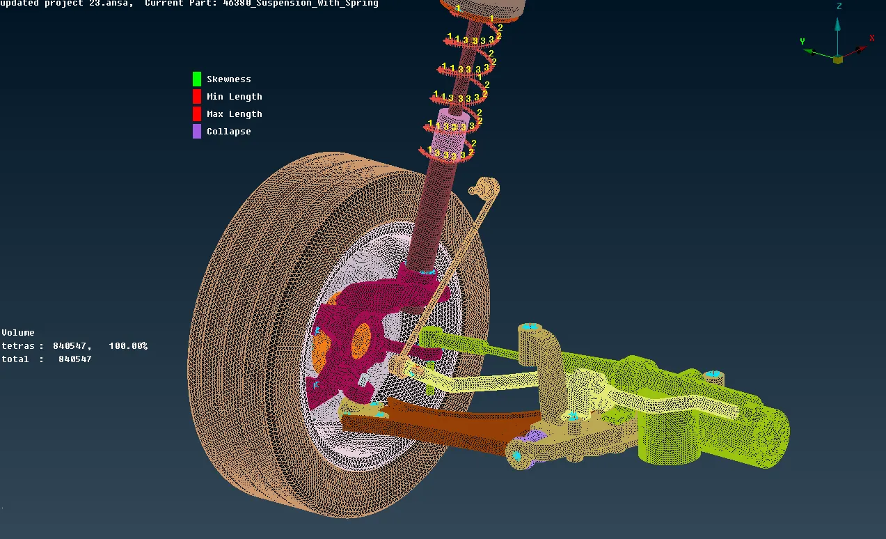
Project 2 -Modeling of an automotive suspension assembly using ANSA
Aim: For the given suspension assembly, check for the geometrical errors and mesh with the given element Quality criteria. After meshing the component, the thickness has to be assigned for mid surfaces. Use tetra elements to model non-uniform thickness components and also making the required connections.
Quality Criteria for Tria Elements (Tyre and Rim):
|
S.No |
Quality Criteria |
Value |
|
1 |
Target/Average length |
6.5 |
|
2 |
Minimum Length |
5 |
|
3 |
Maximum Length |
10 |
|
4 |
Skewness |
45 |
Quality criteria for Mixed elements (For Midsurface only):
|
S.No |
Quality Criteria |
Value |
|
1 |
Target/Average length |
4 |
|
2 |
Minimum Length |
2 |
|
3 |
Maximum Length |
6 |
|
4 |
Aspect |
3 |
|
5 |
Warpage |
15 |
|
6 |
Skewness |
45 |
|
7 |
Jacobian |
0.7 |
|
8 |
Minimum Quad Angle |
45 |
|
9 |
Maximum Quad Angle |
135 |
|
10 |
Minimum Tria Angle |
30 |
|
11 |
Maximum Tria Angle |
120 |
Quality criteria for Tria (For other components):
|
S.No |
Quality Criteria |
Value |
|
1 |
Target/Average length |
4 |
|
2 |
Minimum Length |
2 |
|
3 |
Maximum Length |
6 |
|
4 |
Skewness |
45 |
Common Quality Criteria for Tetra elements are:
|
S.No |
Quality Criteria |
Value |
|
1 |
Tet-collapse |
0.2 |
SUSPENSION SYSTEM:
A suspension system is traditionally created with springs that absorb part of the shock when you hit a bump, allowing the tires and axle to move independently and softening the impact to the rest of the vehicle.
Suspension systems must support both road holding/handling and ride quality which are at odds with each other. The tuning of suspensions involves finding the right compromise. It is important for the suspension to keep the road wheel in contact with the road surface as much as possible, because all the road or ground forces acting on the vehicle do so through the contact patches of the tires. The suspension also protects the vehicle itself and any cargo or luggage from damage and wear. The design of front and rear suspension of a car may be different.
Types of suspension system
1) INDEPENDENT SUSPENSION SYSTEM
This system means that the suspension is set-up in such a way that allows the wheel on the left and right side of the vehicle to move vertically independent up and down while driving on the uneven surface. A force acting on the single wheel does not affect the other as there is no mechanical linkage present between the two hubs of the same vehicle. In most of the vehicle, it is employed in front wheels.
This type of suspension usually offers better ride quality and handling due to less unsprung weight. The main advantage of independent suspension is that they require less space, they provide easier steerability, low weight, etc...
Examples: Double Wishbones, MacPherson Strut
2) DEPENDENT SUSPENSION SYSTEM
In Dependent Suspension there is a rigid linkage between the two wheels of the same axle. A force acting on one wheel will affect the opposite wheel. For each motion of the wheel caused by road, irregularities affect the coupled wheel as well.
It is mostly employed in heavy vehicles. It can bear shocks with a great capacity than independent suspension.
Examples: Solid axle
3) SEMI-INDEPENDENT SYSTEM
This type of system has both the characteristics of a dependent as well as independent suspension. In semi-independent suspension, the wheel moves relative to one another as in independent suspension but the position of one wheel has some effect on the other wheel. This is done with the help of twisting suspension parts.
Examples: Twist Beam
Procedure:
- First importing the model, studied the geometry which one we can make 2d mesh and which parts we can make 3d mesh so according to that the type of mesh is chosen.
- Before choosing the mesh type firstly we need to arrange the parts of suspension system to separate from main part and locking the parts so that we can easily find out the errors in the geometry and also helpful in meshing.
- After arranging all the parts separately for every part we need to check the geometry errors using tools > checks > Geometry, and clicking on the geometrical problems of the model such as Unchecked Faces, Needle Faces, Collapsed Cons, Triple Cons, Overlaps, Single cons and Cracks. Clicking on the execute option and finding the errors in the surfaces. If any errors found that as been cleared using the automatic fix option or manually cleared using the topo option.
- After clearing the geometrical errors, the given quality criteria values as been assigned using the quality criteria option selecting the whichever criteria needed and adding the values to it and in mesh parameters giving target length, min length and max length values.
- After fixing the geometrical errors and using mesh > length > selecting all the perimeters and giving the nodal distance.
- As there are some surfaces are failing for minimum element length so that type of surfaces are toggled or created the mid line between the lines and toggled the other two lines.
- Then using mesh > mesh generations > spot mesh > ortho tria mesh as been done on the surfaces where the more load going to act and also on the fillets and connections otherwise normal tria as been used wherever possible, where we can’t use the ortho tria on all the surfaces due to more computational time will taken by ortho tria’s
- After creating the 2D tria elements and clearing all the min and max tria elements criteria. As some surfaces are failing the minimum element length due to less area of the surfaces so that type of surfaces are left as it is for failing the minimum element criteria.
- For creating 3D elements first creating the property using volumes > define > manual > New.
- Using V mesh > unstructured mesh > tetra rapid. 3D tetra elements are created.
- If any tet collapse failed using MV free or move options are used to move the elements so that it won’t fail for tet collapse or otherwise using improve > fix quality to clear it but using auto fix quality option the surface may create kinks and dips so it better to use mv free or move options.
- For 2d mesh thickness measurement as been taken randomly and mid surface is extracted using Topo > faces > offset > faces. Selecting the faces on any one side and giving the offset value of exact middle and creating the mid surface.
- Using mesh options mesh generation > best > select, options mesh as been created on the surfaces one by one and for proper mesh using mesh > mesh generation > reconstruct > select, options is used for good mesh and get the mesh flow good smooth option is used.
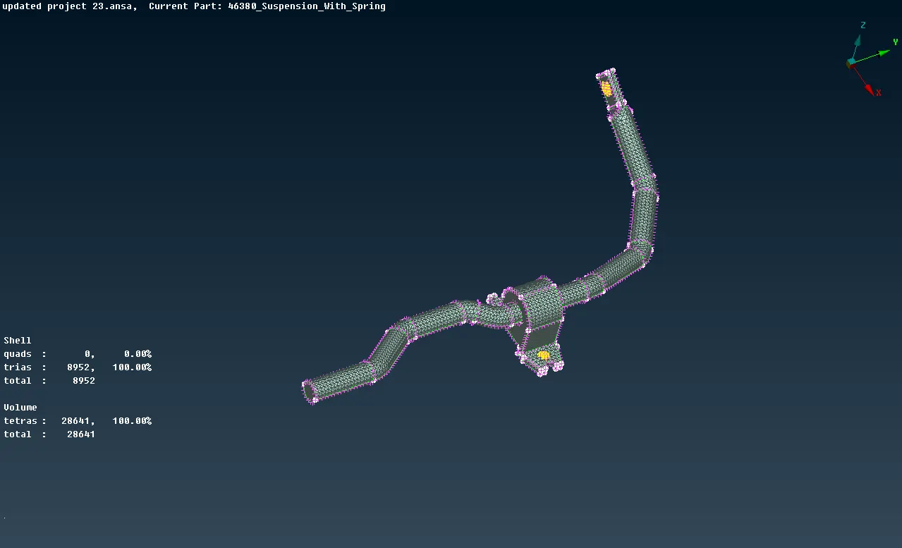
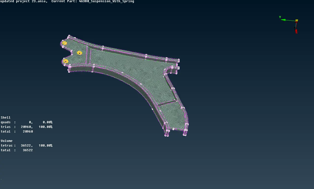
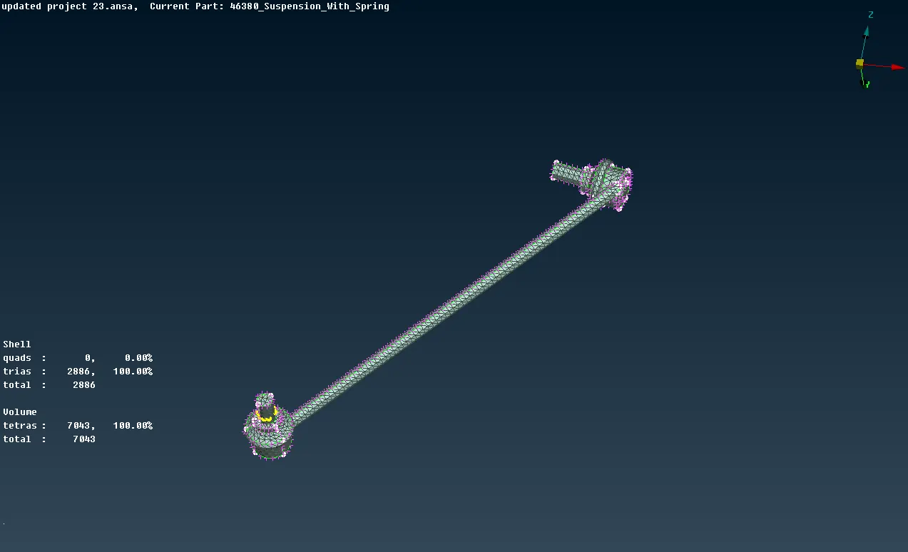
- After completing the mesh for assigning the thickness mesh > macros > set PID > selecting the faces > by clicking on the right click > new > Pshell > giving the thickness value > then press Ok.
- There are different type of connections available like RBE2, RBE3, CBAR, CBEAM, CBUSH, CONMI, SPOT WELD, SEAM WELD, etc., and surfaces are connected according to the requirement.
- For bolt connection representation there are mainly two ways we can represent first is using Nastran > elements > RBE2 > many nodes > selecting the slave nodes > automatically master node is created according to the convex hull centroid > it gives the details of element id, master id, number of nodes, degrees of freedom > after checking the all values and entered finish.
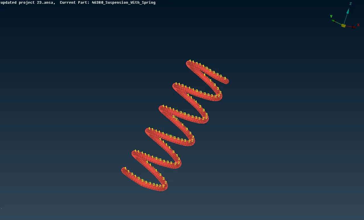
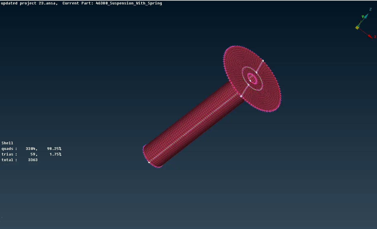
- Another way of representing the bolt is creating the COG using the on COG > edges > selecting the edges. After creating COG converting 3D points to bolt > connection selection assistant > selecting on the 3d point of bolt and middle click > selecting the P1, P2, P3 > FE Rep type to bolt > giving the search distance and zones as in/out > applying and realizing.
Learning outcomes:
- Learnt all the major thing in modelling like extracting the mid surface, 2d meshing, 3d meshing, making the connections in single model.
- As time is very important in modelling so far I improved a lot in time managing.
Conclusion:
For the given assembly, checking the geometrical errors and meshed with the given element Quality criteria. After meshing the component, the thickness has been assigned for mid surfaces. Using tetra elements to model non-uniform thickness components and also making the required connections.