ANSA Project - REAR SUSPENSION ASSEMBLY - Shell and Solid meshing and Connections deployment
AIM
To check the geometrical errors for the given rear suspension assembly and mesh with the given element Quality criteria. After meshing the component the thickness has to be assigned for mid surfaces. And tetra elements to be used to model non-uniform thickness components. Also use connections to connect the component.
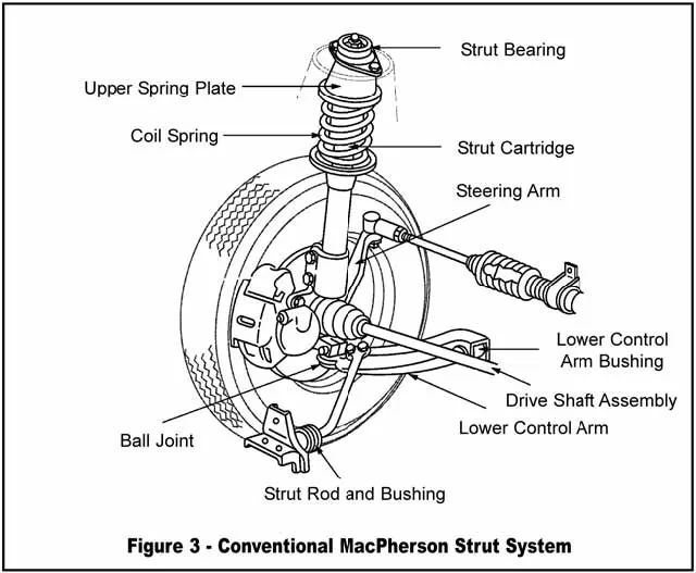
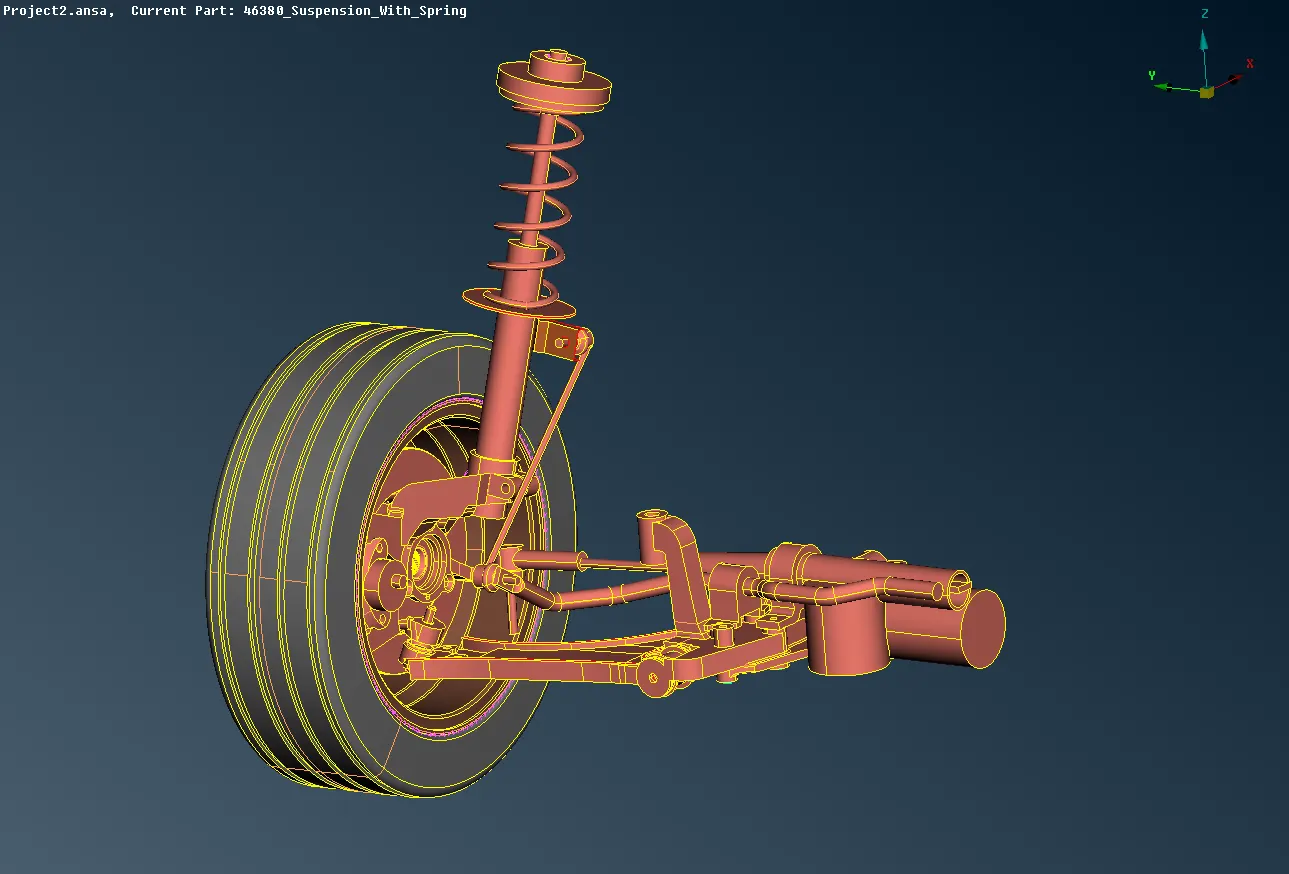
The Given component here is Rear Suspension Assembly.
QUALITY CRITERIA
For Tria elements (Tyre and Rim)
| S.No | Quality Criteria | Value |
| 1 | Target / Average Length | 6.5 |
| 2 | Minimum Length | 5 |
| 3 | Maximum Length | 10 |
| 4 | Skeweness | 45 |
For Mixed elements (Midsurfaces only)
| S.No | Quality Criteria | Value |
| 1 | Target / Average Length | 4 |
| 2 | Minimum Length | 2 |
| 3 | Maximum Length | 6 |
| 4 | Aspect | 3 |
| 5 | Warpage | 15 |
| 6 | Skeweness | 45 |
| 7 | Jacobian | 0.7 |
| 8 | Minimum Quad Angle | 45 |
| 9 | Maximum Quad Angle | 135 |
| 10 | Minimum Tria Angle | 30 |
| 11 | Maximum Tria Angle | 120 |
For Other Tria Elements
| S.No | Quality Criteria | Value |
| 1 | Target / Average Length | 4 |
| 2 | Minimum Length | 2 |
| 3 | Maximum Length | 6 |
| 4 | Skeweness | 45 |
Common Quality Criteria for Tetra elements
| S.No | Quality Criteria | Value |
| 1 | Tet Collapse | 0.2 |
Definitions of Quality Criteria
1. Aspect Ratio :
The aspect ratio of 2D element is defined as the ratio of its shortest edge length to its longest edge length. A square has the aspect ratio of 1 since its sides have the same length. As it gets away from the square shape, the aspect ratio becomes smaller than 1.
2. Skew Angle
An angle is formed by the two lines which pass through the midpoints of the sides of the quadrilateral. The skew angle represents the absolute value of the difference between the angle and 90 degree. A rectangle has the skew angle of 0 since the formed angle between lines is 90 degree. For the triangle and quadrilateral elements, the skew angle is found as shown in the figure. For solid element (Tetra, Hexa, Wedge), it calculates the skew angle for each element faces and assigns with the minimum value.
3. Warpage
The warpage of the quadrilateral elements is defined as the deviation from a best-fit plane that contains the element. It is not always a case to define a plane with 4 nodes. Therefore, a node of the quadrilateral element may be formed outside of a plane. The warpage is a measurement how this node has been deviated, and as it gets closer to 0, the element become more planar. For the quadrilateral elements, the warpage is found as shown in the figure. For solid element (Hexa, Wedge), it calculates the warpage for each element faces and assigns with the maximum value.
4. Jacobian Ratio
The Jacobian calculation is done at the integration points of elements commonly known as Gauss Point. At each intergration point, Jacobian Determinant is calculated, and the Jacobian ratio is found by the ratio of the maximum and minimum determinant value. The Jacobian Determinant of 2D elements is calculated after it has been projected on to a plane, and the determinant of 3D elements is found by direct calculation. If the quadrilateral element is not convex, the negative Jacobian ratio will be obtained, and elements with the negative Jacobian Ratio can not be solved with correct result.
5. Collapse
When auto-generating a mesh in a complex or invalid geometry. A tetra element, which seems as thin as a planar element, will be often generated. This type of the element is called as a collapsed tetra, and this option enable to check for such a collapsed element.
PROCEDURE
1. Midsurface
First The given rear suspension assembly model is opened and Geometry Check is done and some errors are autocorected and some errors are manually corrected. And the elements which are having thickness less than 5mm are seperated and length is set under quality constrains. For midsurface Perimeter and Macro Length are set as 4.
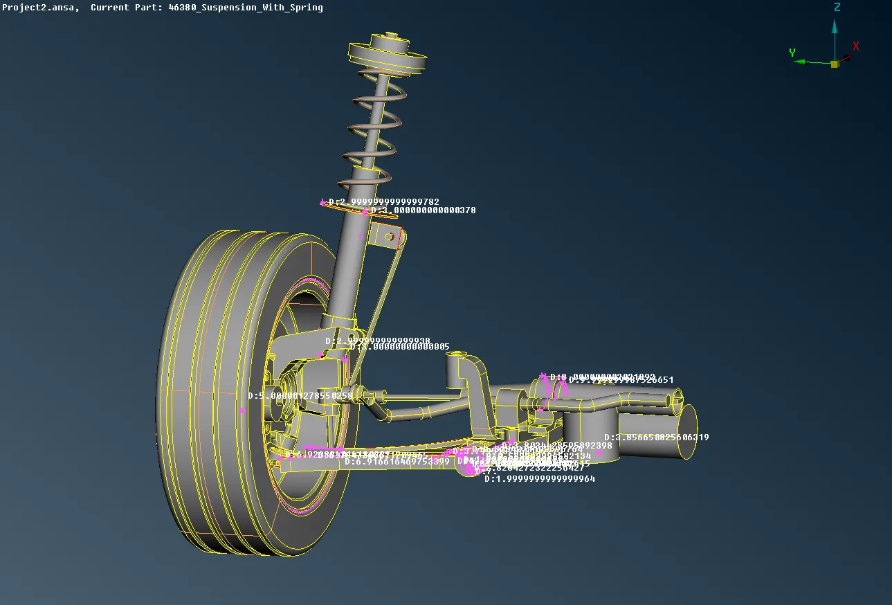
Thickness are measured for the elements and Midsurfaces are taken with Offset option.
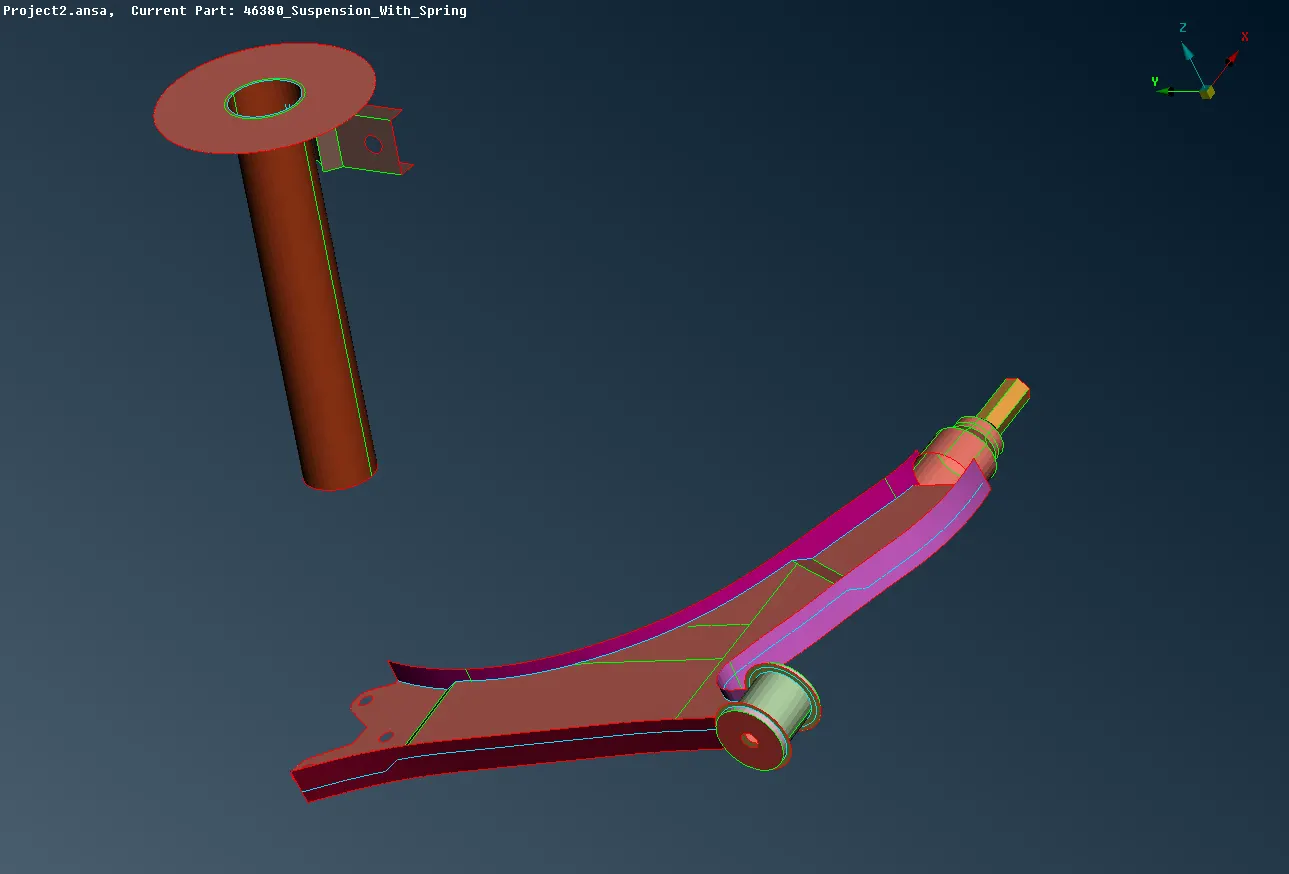
Mesh is deployed with Spot mesh option in Mesh Mode. And errors are corrected with help of Reconstruct, Smooth. And for given Quality criteria, Mesh is deployed with zero errors.
2. Tyre and Rim Elements
Tyre and Rim are set in seperate PID and taken and Mesh are deployed on the surface as Surface Mesh to generate the Volume mesh. Length is set to given Average Length as 6.5mm.
Surface mesh is deployed with the Tetra elements like Ortho Tria in curved areas and Tria in plane surfaces with given quality criteria constrains and zero errors are obtained for surface mesh.
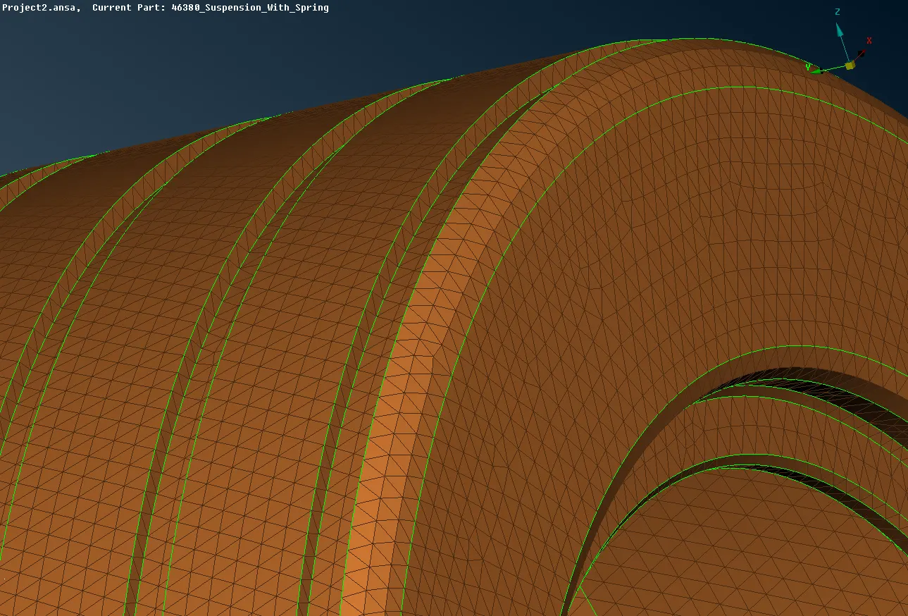
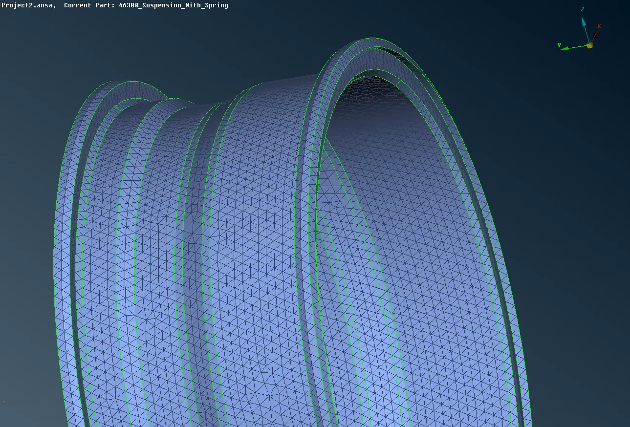
And made sure that surface didnt have any raised edges and the surface is captured in a perfect manner.
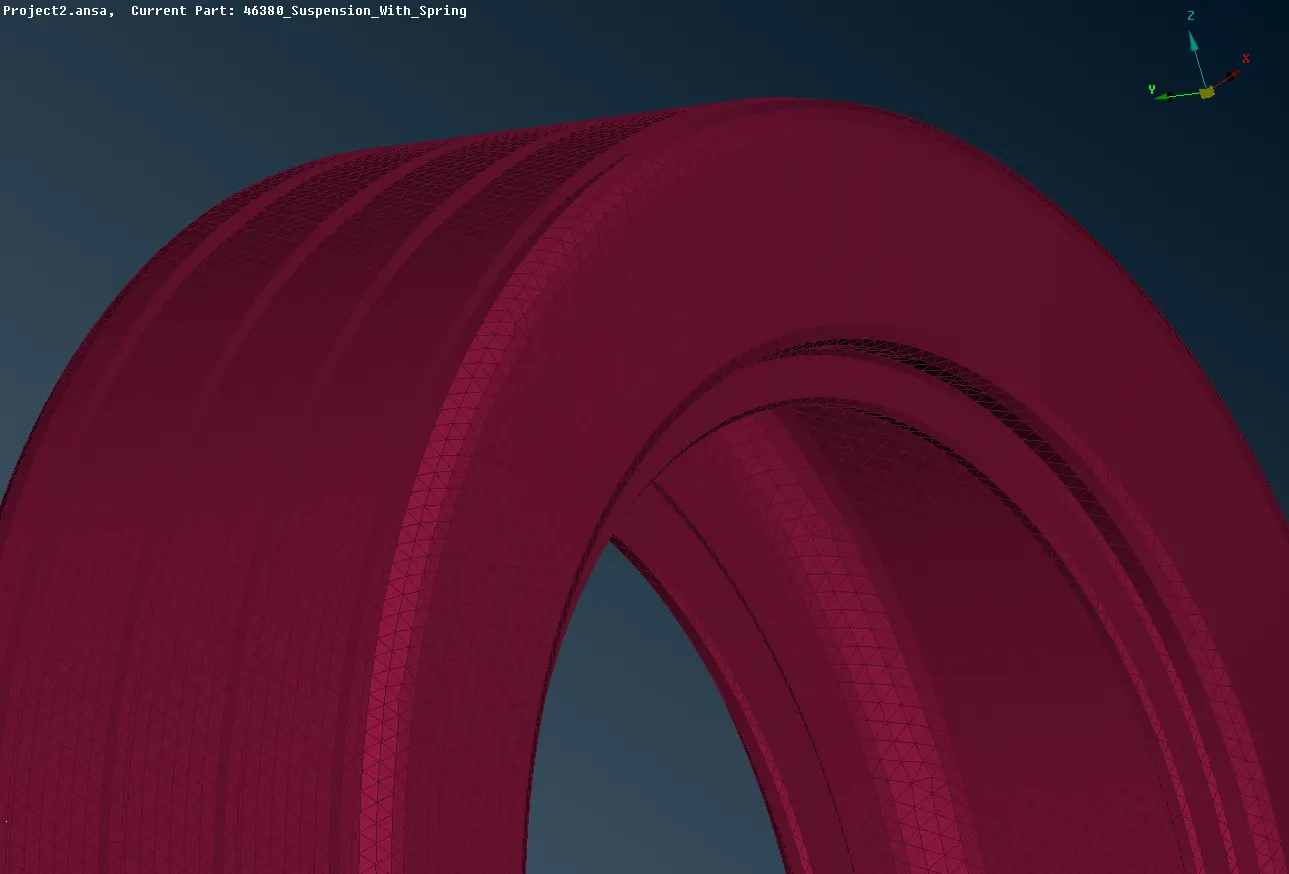
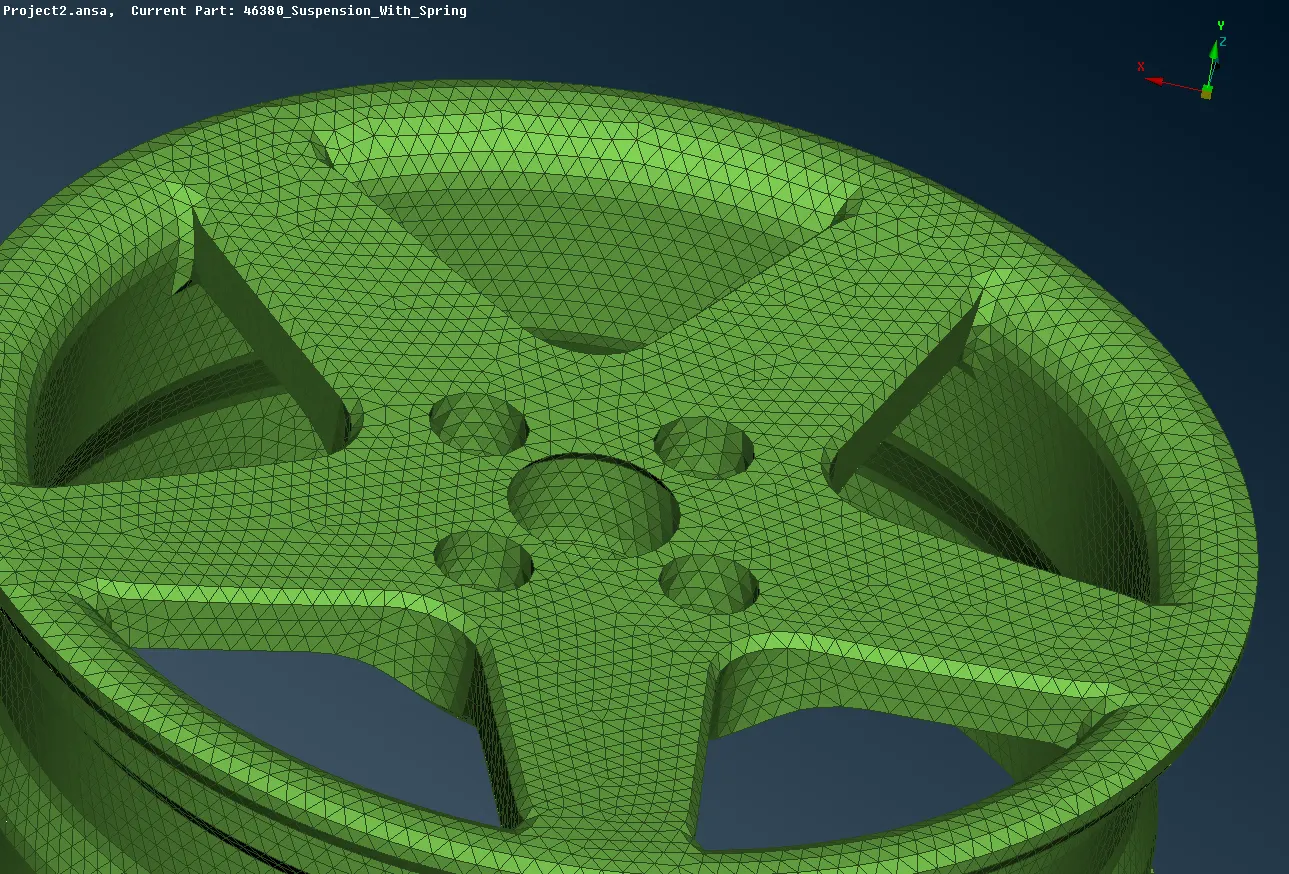
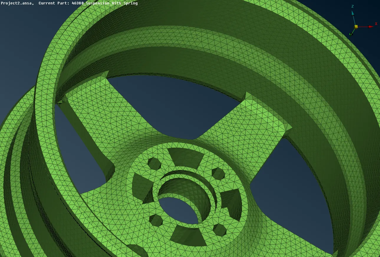
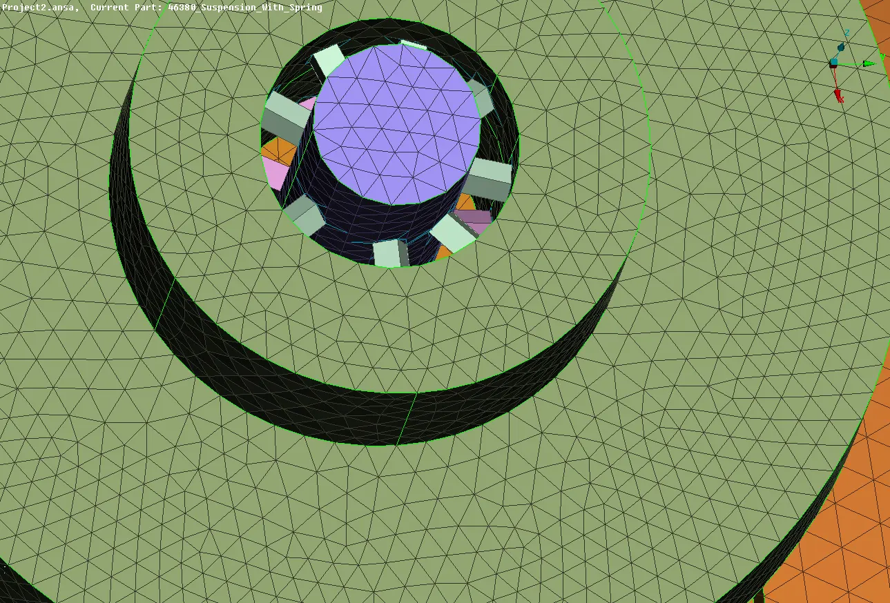
Volume mesh is obtained by following steps, First the element is defined as a closed volume in Define in Volume Mesh Module. And the element is defined as a closed volume as PSOLID and the the property is assigned in LIST option. Right click in that and Remesh is selected and TETRA RAPID is selected for the volume mesh.
Volume mesh is deployed and made sure that the volume mesh is free of collapse quality criteria and raised edges are moved to get a perfect mesh generation. Volume mesh is deployed in Tyre and Rim.
3. Tria Elements
Suspension assembly contains many elements. Each and every elements are seperated using INOT option with PID Region. And Each and every element is checked for geometry errors and errors are manually corrected and Length are assigned as per the quality criteria given above. Here length is assigned as 4mm.
Surface mesh
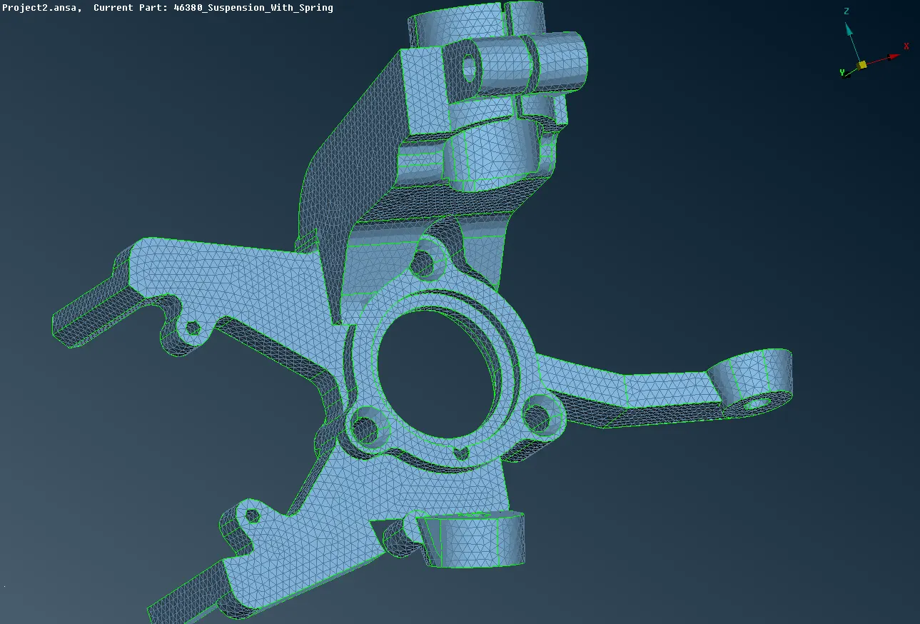
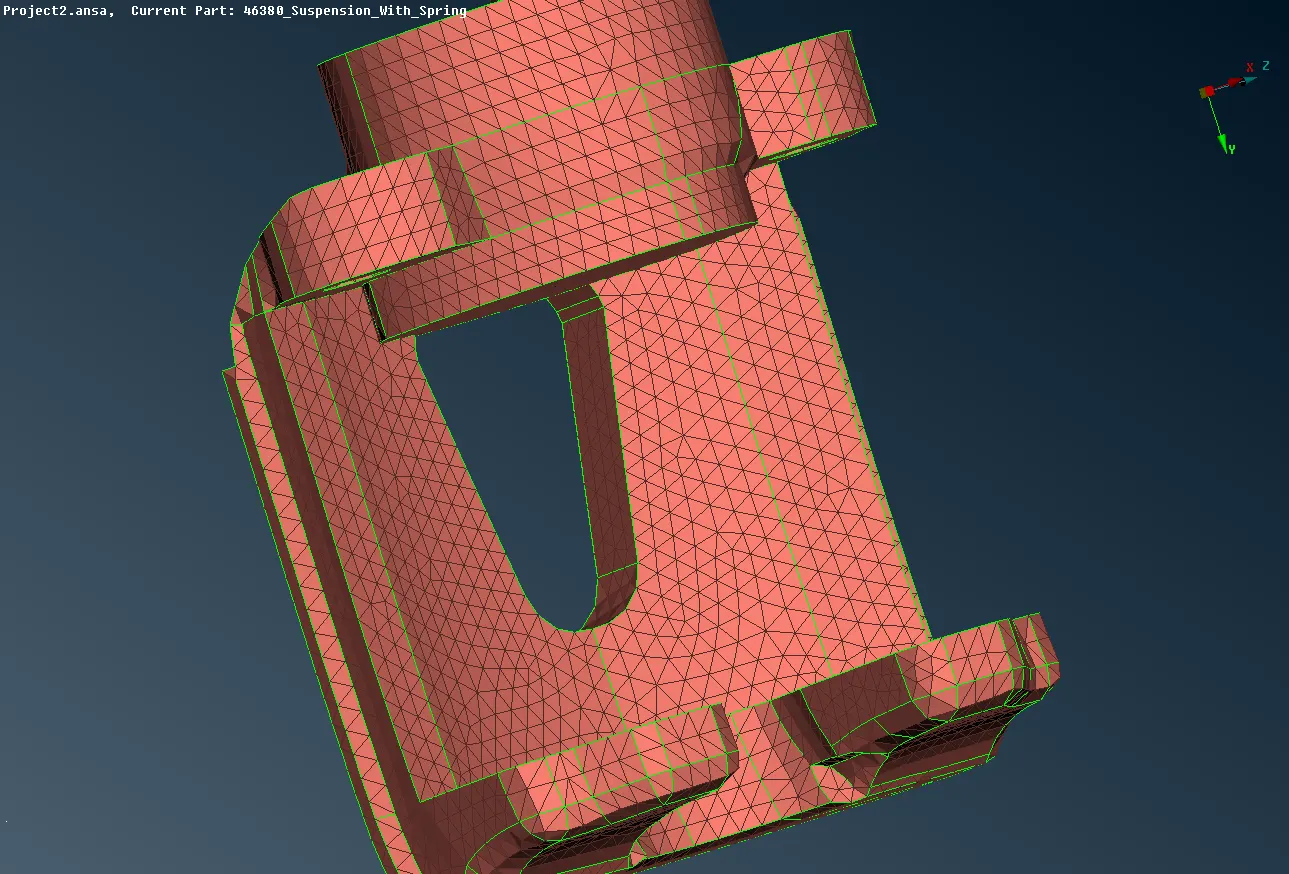
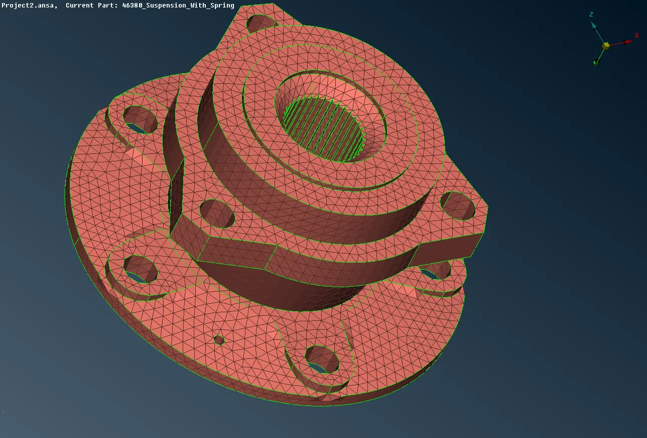
Surface mesh is deployed with help of Ortho tria and Tria elements on the surfaces. Ortho tria is deployed on the curved surfaces and Tria is deployed on the plane surfaces. And no raised and lower edges are to be present in th surfaces.
Volume Mesh
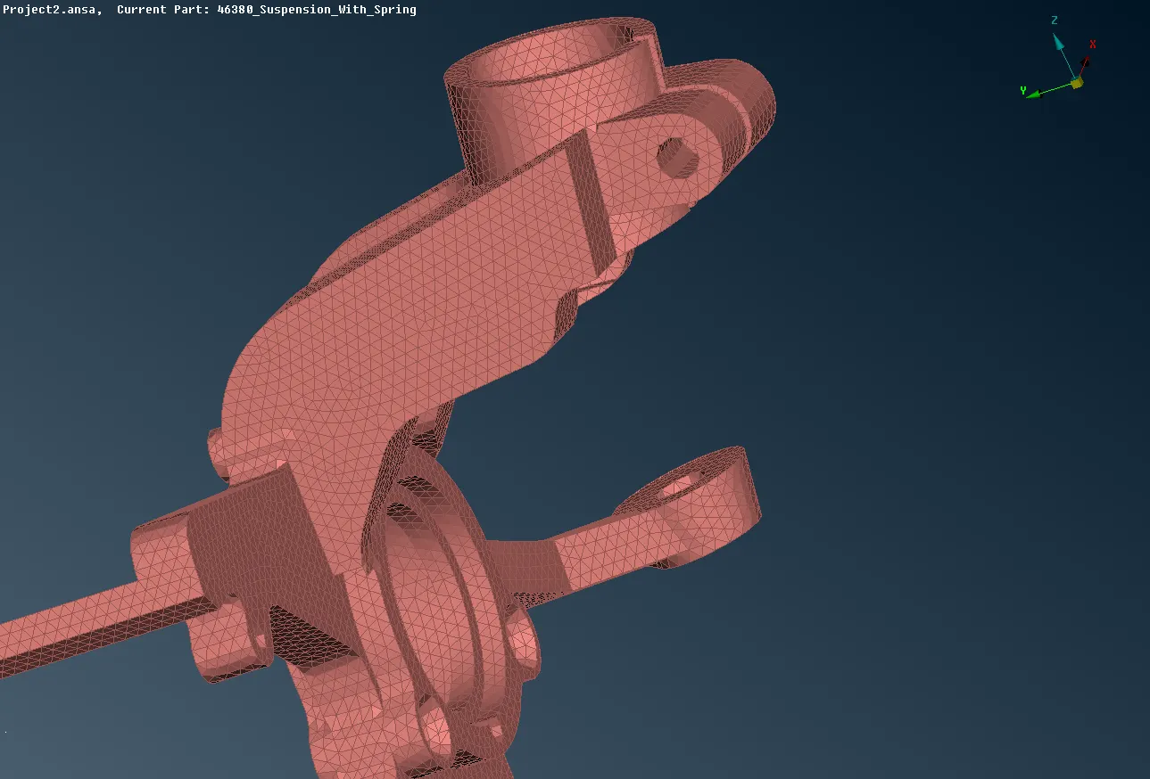
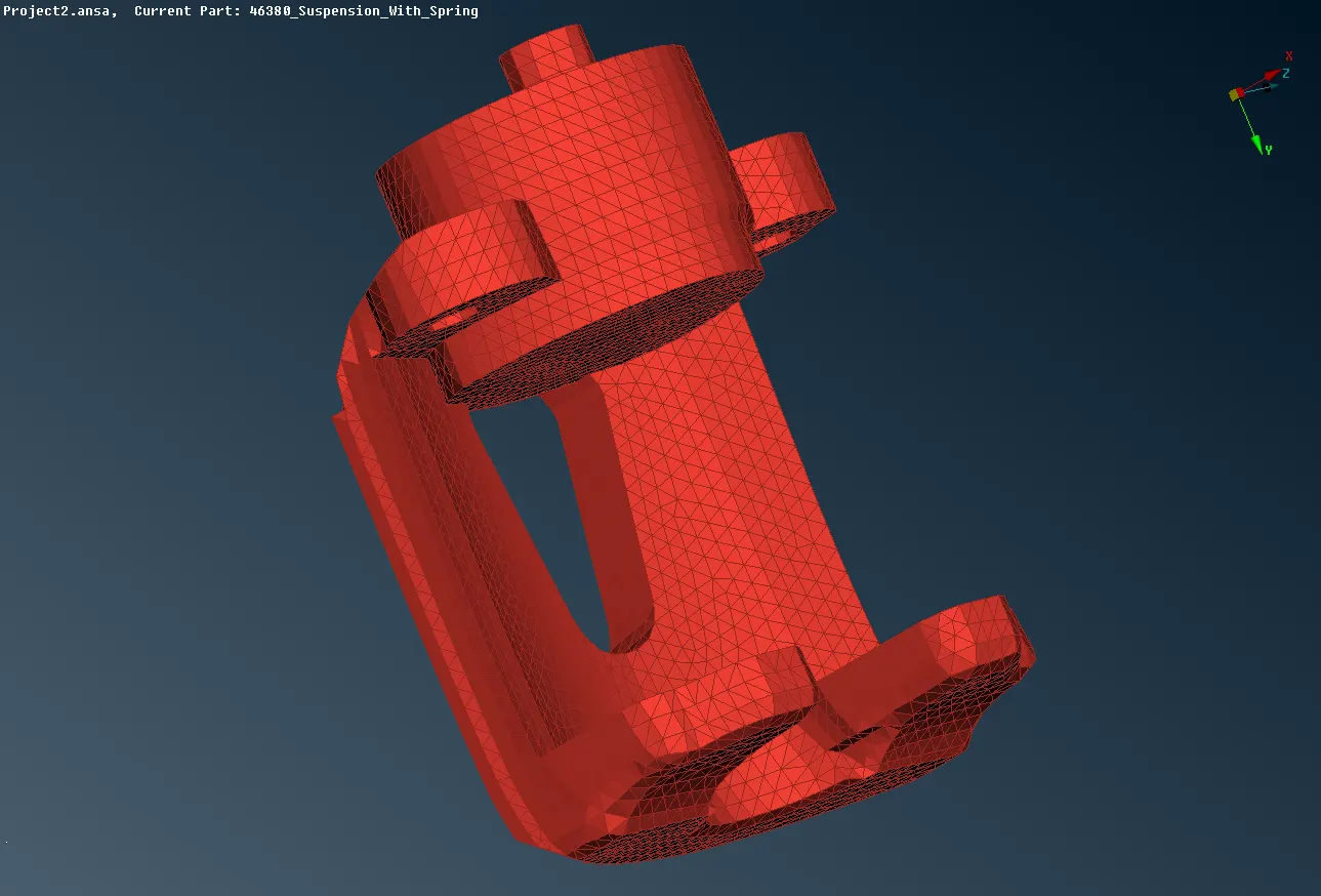
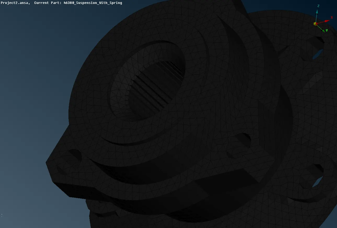
And Volume mesh is deployed as deployed in rim and tyre by defining it as a closed volume and in List it is remeshed with Tetra Rapid option. And the deployed volume mesh is corrected to make it as error free mesh. Volume mesh should be free of collapese quality criteria.
Mesh is deployed in all area.
Complete volume mesh
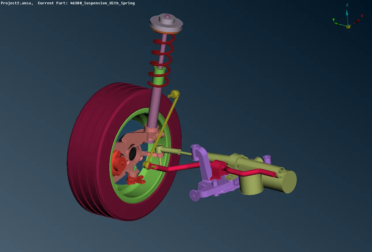
CONNECTIONS
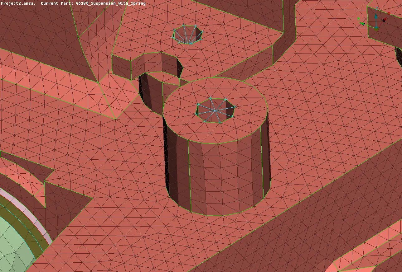
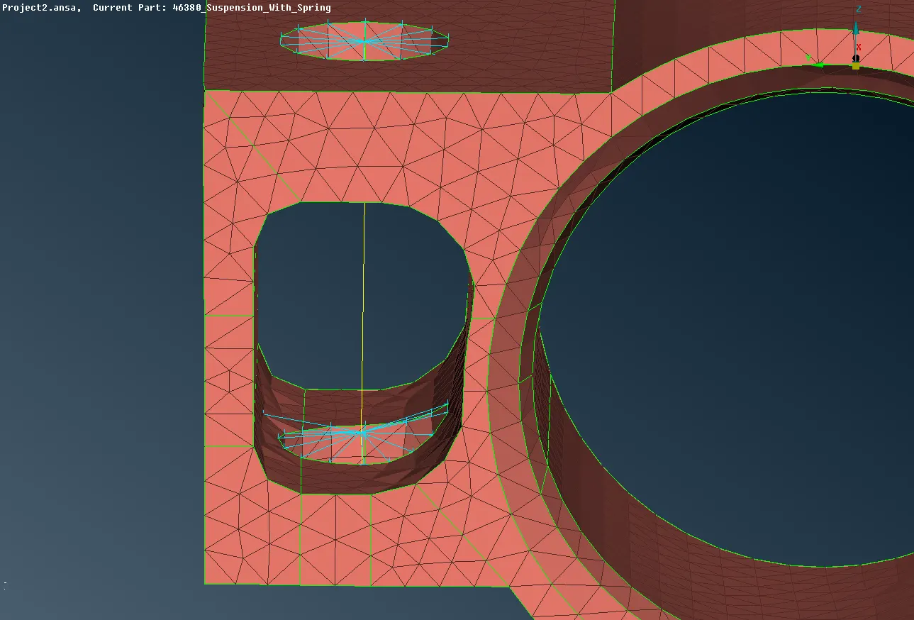
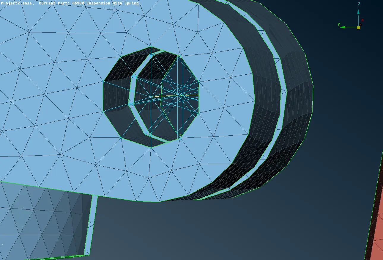
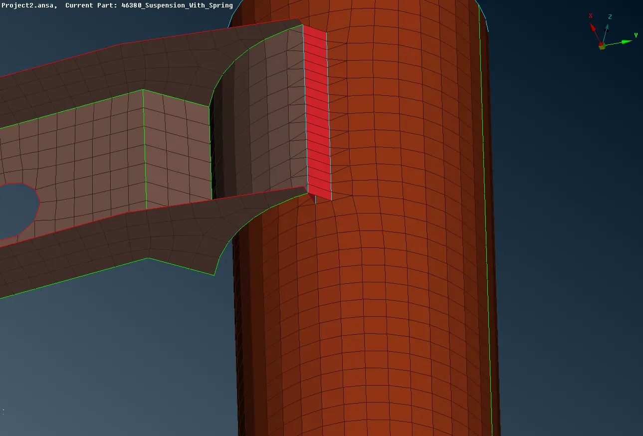
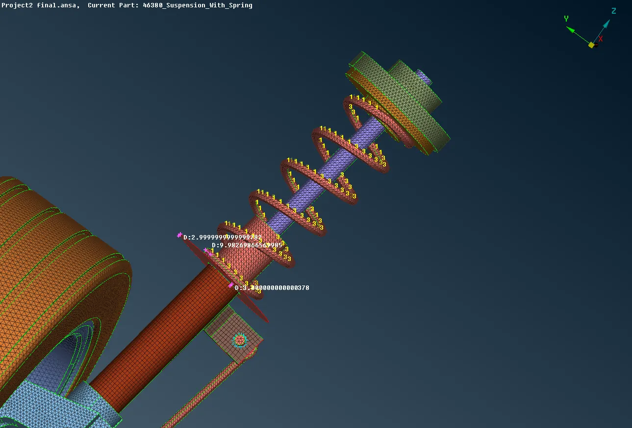
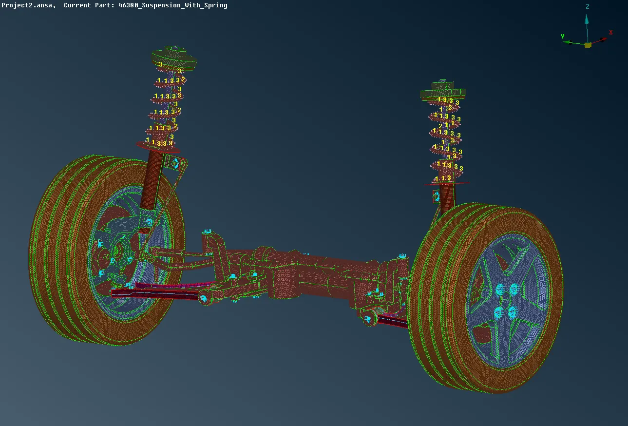
Connections are made in volume mesh but it'll be visible only in FE mode. There are many types of connections like RBE CONNECTIONS, SPOTWELD, SEAMWELD, CBAR CONNECTIONS.
RIGID BODY CONNECTIONS
SEAM WELD CONNECTIONS
SPOT WELD CONNECTIONS
CBAR CONNECTIONS
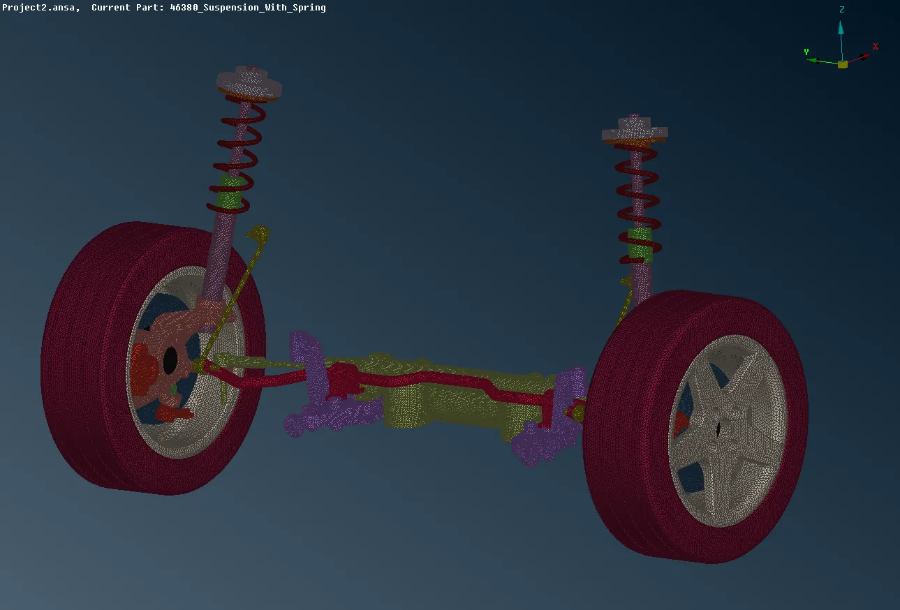
Thus all voulme meshes are deployed and 2D mesh in appropriate areas and connections are given and TRANSFORM -> COPY is given and the hole entity is selected and copied with the 3 axis and thus the entire REAR SUSPENSION ASSEMBLY is obtained.
LEARNING OUTCOMES
- From this project model have learnt to study the model entirely before starting with the mesh which will help to make judgement where the mid has to be extracted and where the surface mesh should be deployed.
- Have exprienced working on critical areas for volume mesh
- And have learnt on connecting those areas.
CONCLUSION
Hereby concluding that have finished mid surface extraction and mesh deployment and volume mesh is generated and connections were done in suitable areas.
GOOGLE DRIVE LINK
https://drive.google.com/file/d/1UVg2MW8IViv1sIUUNEq6yrRgc4MBvIRV/view