Performing the meshing and connections of car rear suspension model
OBJECTIVE - To check geometrical errors,meshing and implementing the connection to the car rear suspension model with the given mesh and quality parameters.
METHODOLOGY -
- Import geometry and topological cleanup.
- parts segregation under different property id.
- Defeaturing the model.
- Midsurface extraction if the component having uniform thickness less than 5mm.
- Set up mesh parameter and quality criteria as per given.
- shell meshing and correction.
- Volume definition and 3D Mesh generation other than midsurface components.
- implementation of connections at required area.
Component of car suspension system - 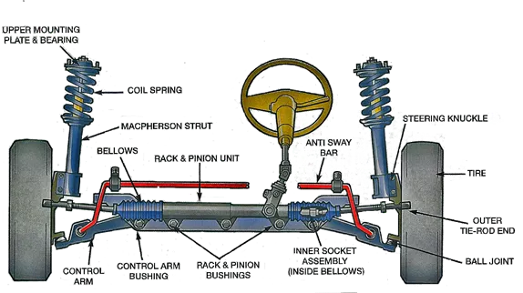
fig. different part of suspension system
PROCEDURE -
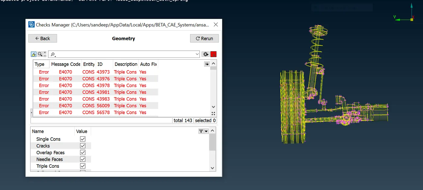
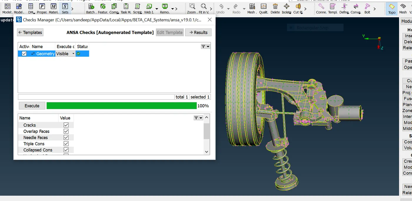
Geometry cleanup - first of all, we need to import the Cad model into ansa interface. then give a Topo for the entire geometry . then go for a geometry checkup and fix all the geometrical or topological errors likes triple cons, face overlap, crack face etc to proceed to the next steps.
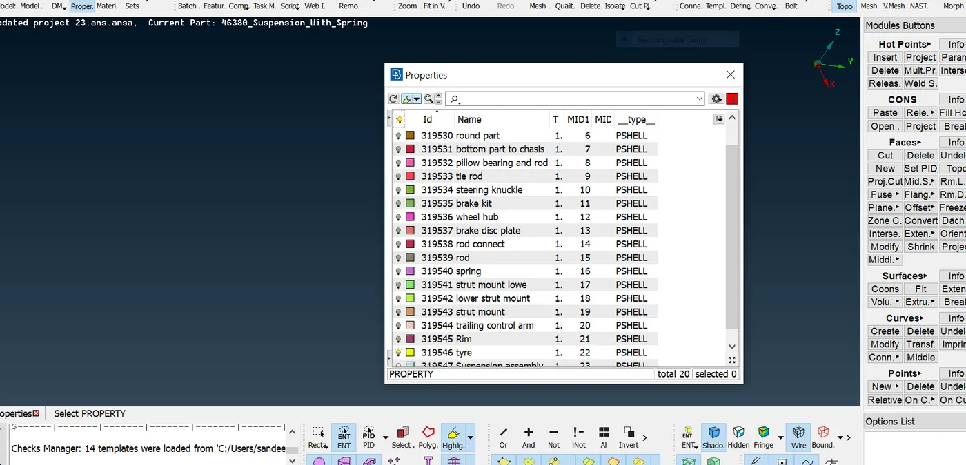
Segregation of parts under different property id - now next step is to segregate different parts under property id so as to proceed part by part which helps to expedite the process of pre-processing.
Defeaturing of component - So as to capture the component properly we need to deafeature the unwanted construction line, fillet edges etc before going for meshing the component.
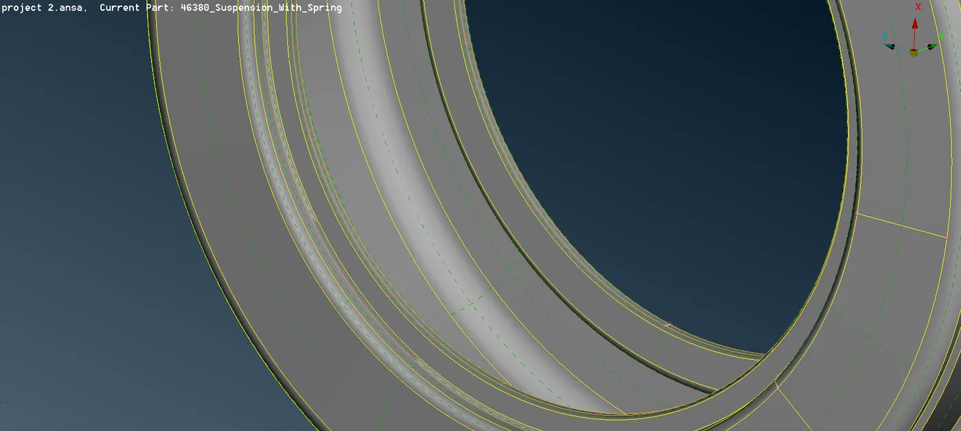
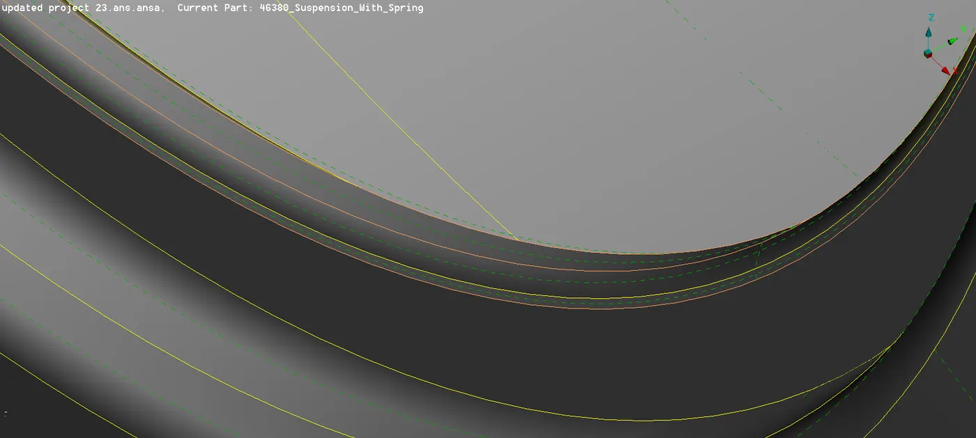
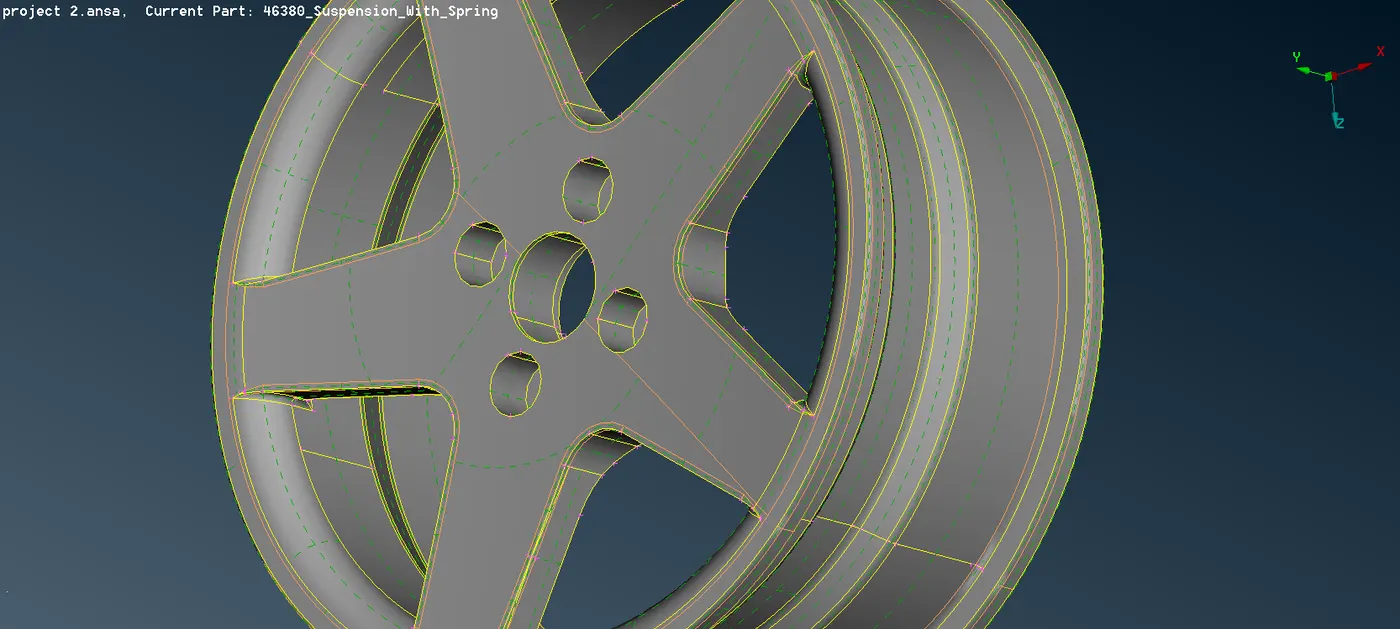
fig. Defeaturing of wheel rim and tyre.
Midsurface extraction of the component have uniform thickness less than 5mm - There are some parts that have a uniform thickness less than 5mm and for those , we will go with the midsurface extraction strategy with offset option. after that we will assign a new pid to midsurface component.
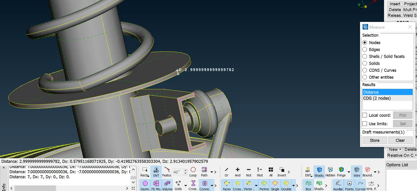
fig. Measuring thickness of disc.
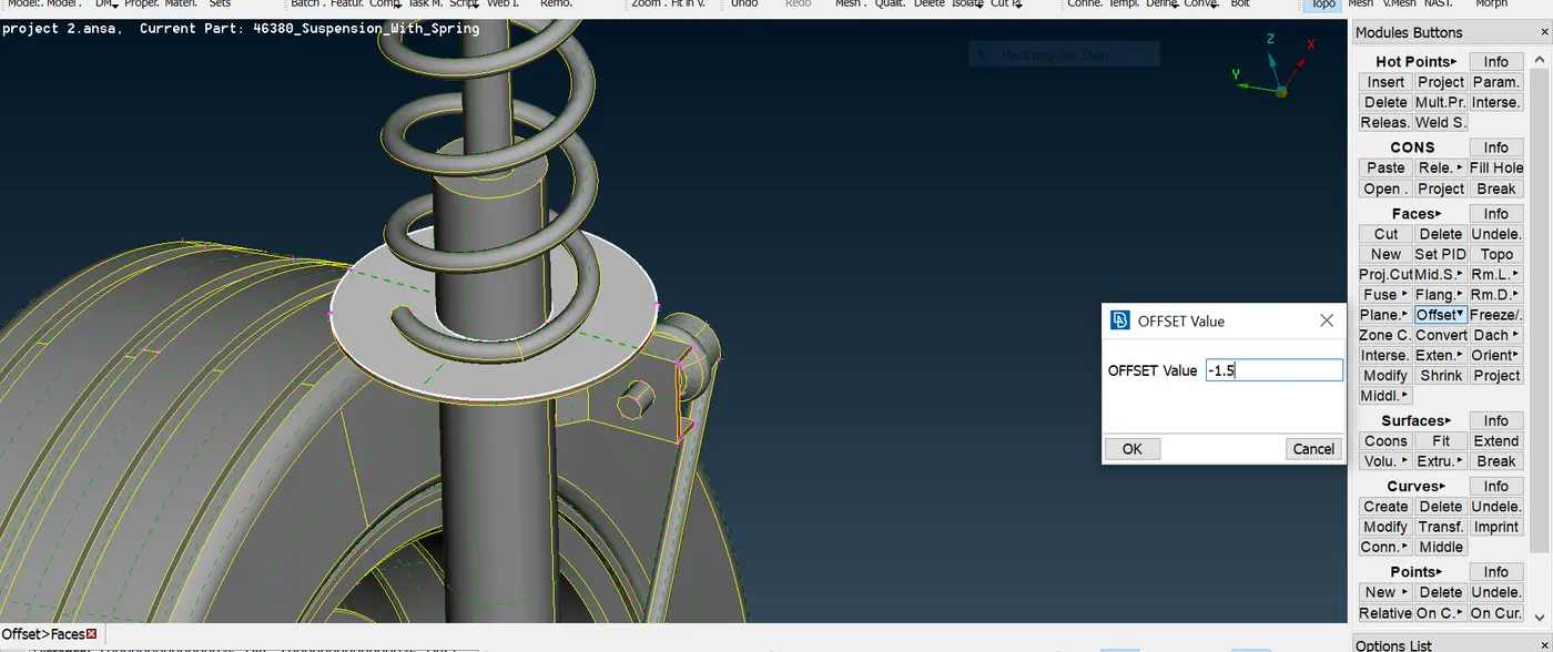
fig. midsurface extraction by offset method
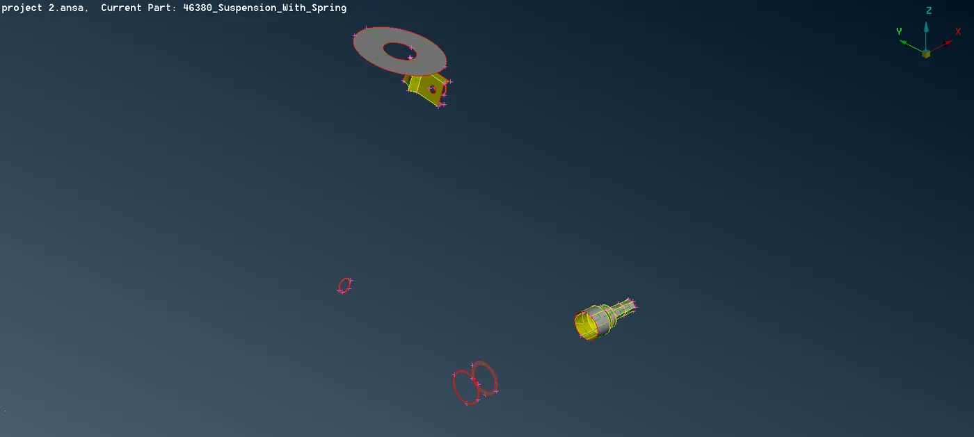
fig. midsurface of different component
Set up mesh parameter and quality criteria as per given requirement -
Quality Criteria for Tria Elements (Tyre and Rim):
|
S.No |
Quality Criteria |
Value |
|
1 |
Target/Average length |
6.5 |
|
2 |
Minimum Length |
5 |
|
3 |
Maximum Length |
10 |
|
4 |
Skewness |
45 |
Quality criteria for Mixed elements (For Midsurface only):
|
S.No |
Quality Criteria |
Value |
|
1 |
Target/Average length |
4 |
|
2 |
Minimum Length |
2 |
|
3 |
Maximum Length |
6 |
|
4 |
Aspect |
3 |
|
5 |
Warpage |
15 |
|
6 |
Skewness |
45 |
|
7 |
Jacobian |
0.7 |
|
8 |
Minimum Quad Angle |
45 |
|
9 |
Maximum Quad Angle |
135 |
|
10 |
Minimum Tria Angle |
30 |
|
11 |
Maximum Tria Angle |
120 |
Quality criteria for Tria (For other components):
|
S.No |
Quality Criteria |
Value |
|
1 |
Target/Average length |
4 |
|
2 |
Minimum Length |
2 |
|
3 |
Maximum Length |
6 |
|
4 |
Skewness |
45 |
Common Quality Criteria for Tetra elements are:
|
S.No |
Quality Criteria |
Value |
|
1 |
Tet-collapse |
0.2 |
Shell meshing - The next step is to mesh the geometry with the tria element and we can choose either tia or ortho tria. if in case we need to mesh the feature like fillet or curved faces we will go with the ortho tria since it capture the feature in a proper manner and in the flat faces we can go with the tria since both tria and ortho tria give similar result in flat faces but simulation time of ortho tria is more ,so we preferred trias in flat surfaces.
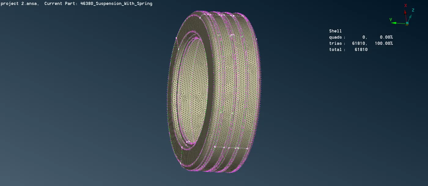
fig . tyre shell meshed
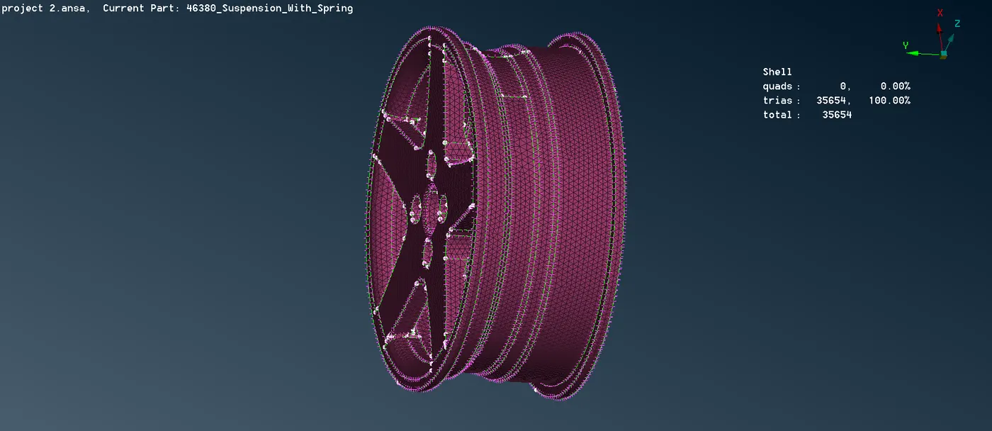
fig. rim shell meshed
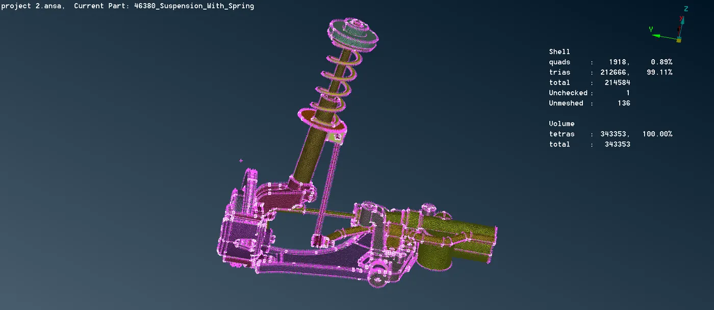
fig. rest of the parts in suspension system
For midsurface component , we are using a Best mesh algorithm and the element type is taken as a mixed type. After that there is lot of quality criteria error are there ,so eliminate these quality errors .
when meshing is done on the complex areas like features, we need to do some reconstruction and smooth function to propely align the element and best quality meshing which should be rid of the quality issues.
In the grid module ,we can find the MV Free which helps in the moving the nodes in order to overcome the quality issues.
Moreover, the options from the module like paste, split, swap, join are used in order to do the meshing properly.
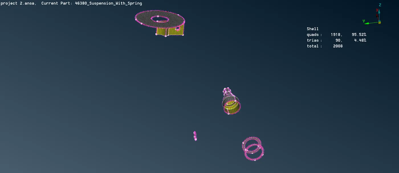
fig. Shell meshing of midsurface component
Volume define and 3D mesh generation - The next step we need to do is define the volume and generate tetra elements through the volume but before defining them on the list we make sure that part is properly meshed and closed . Also the part should not contain any overlapping surfaces. Define them one by one and set different pid type solid as shown in fig. I used Rapid tetra mesh algorithm to auto generate the tetra element inside the volume
we used Volume Mesh Module > Volumes > Define > Manual.
For defining a volume we need already meshed macros FE model mesh.
After defining the shell mesh as a volume in the volume module we need to select the list option from the volume option in the same volume mesh module.
Volume mesh module > Volumes > List
Here we need to select the undefined shell mesh part in volume module and rigth click on it for defining a solid PID for the solid meshing process.
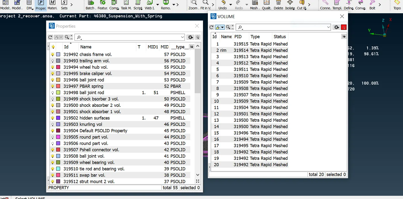
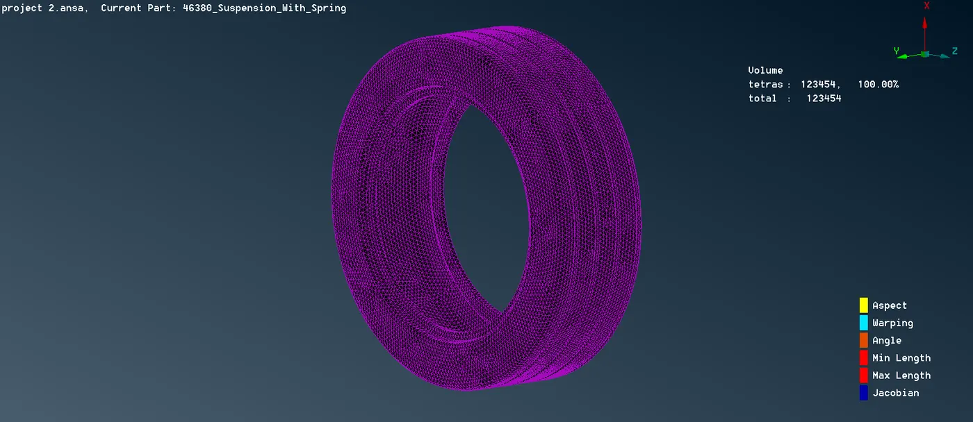
fig. volume meshing in tyre
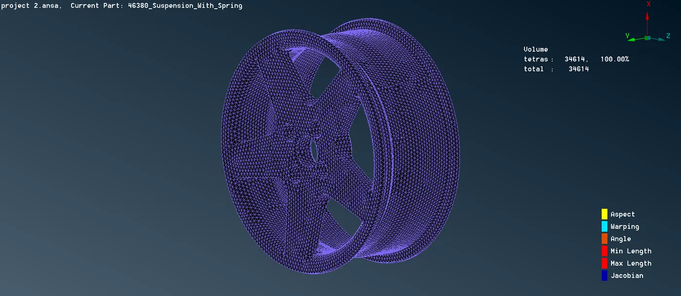
fig. volume meshing in rim
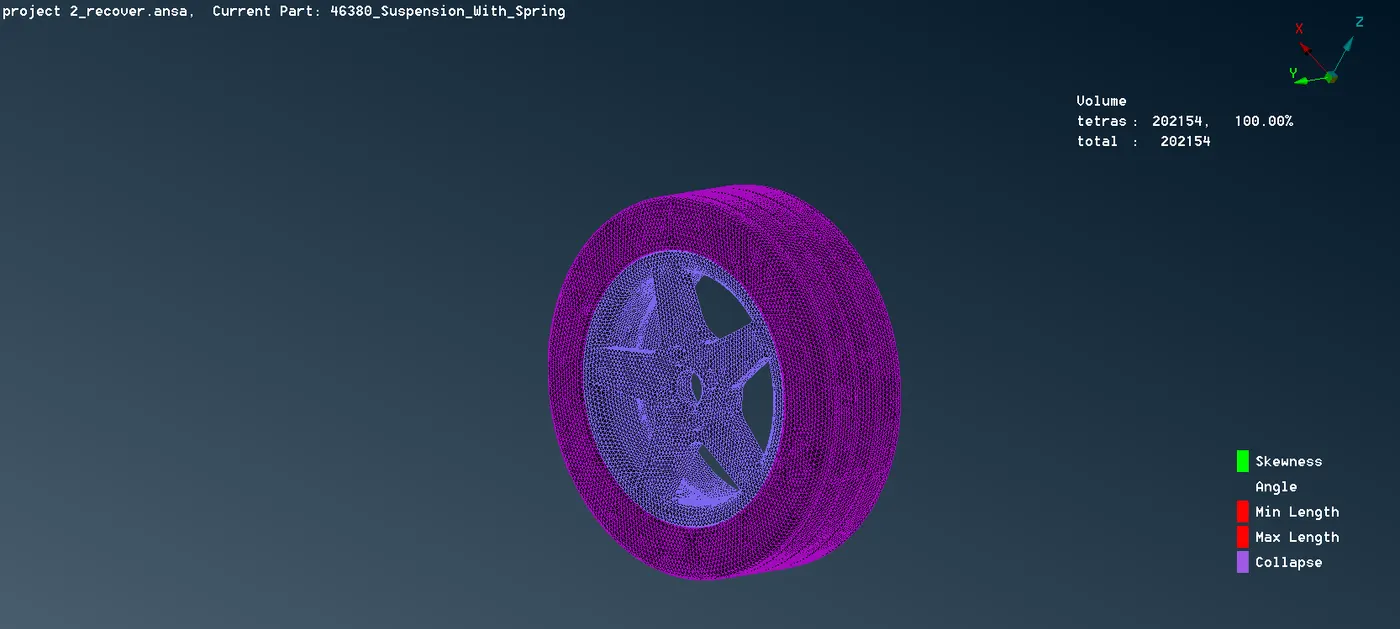
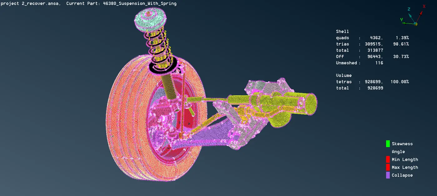
fig. volume meshing in rest part of suspension system
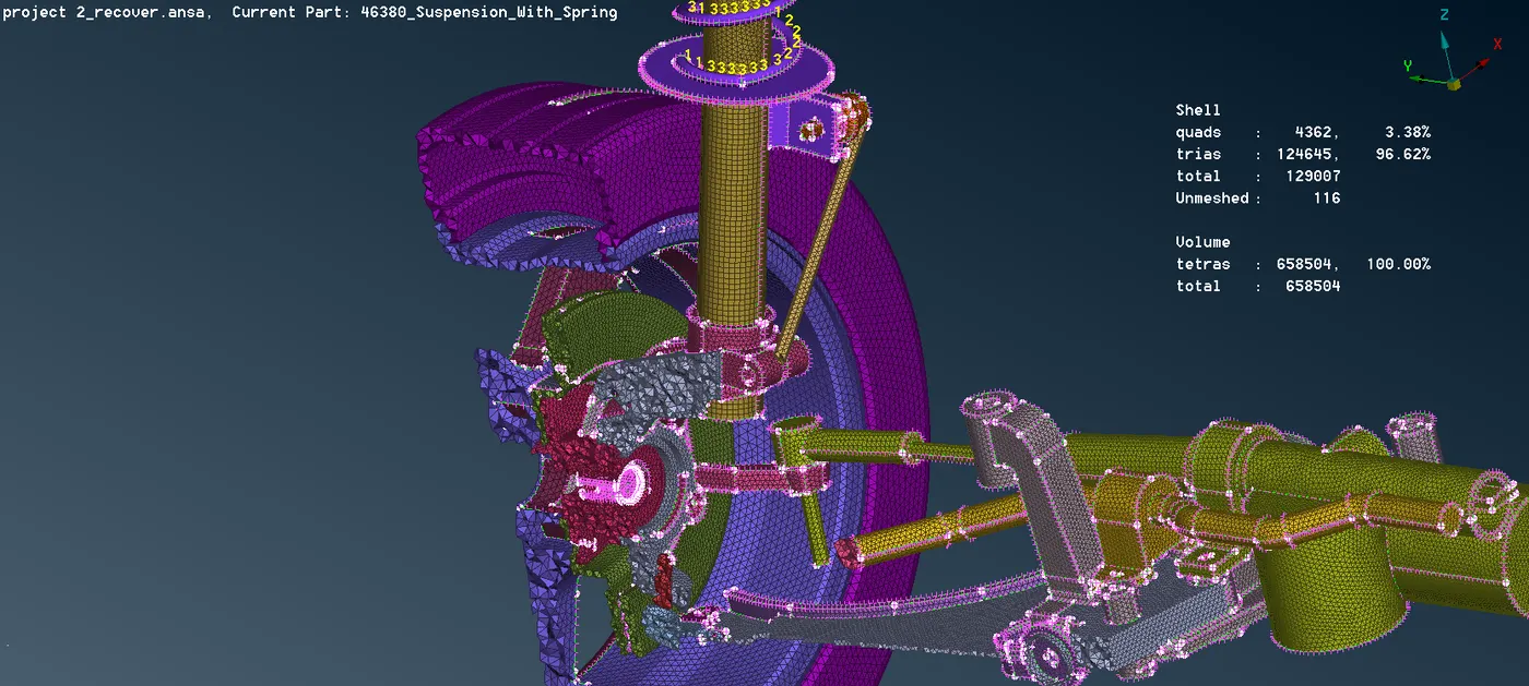
fig. inside view of volume in suspension part
The tetra meshed element are viewed in the hidden mode to check their quality.
Tetra collapse is a major quality condition of tetra elements that should be checked in the volume mesh.
It is make sure that no kinks or raised dips are present in the FE model . If present they are removed manually by using the MV Free option .
Implementation of connection - There are specifics areas that need connection representing weld, bolt and Rigid connections.
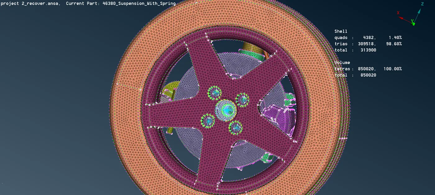
fig. RBE2 cluster connection between rim and wheel hub and 2 node connection in rim.
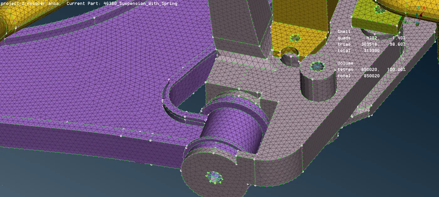
fig. RBE2 two nodes connection
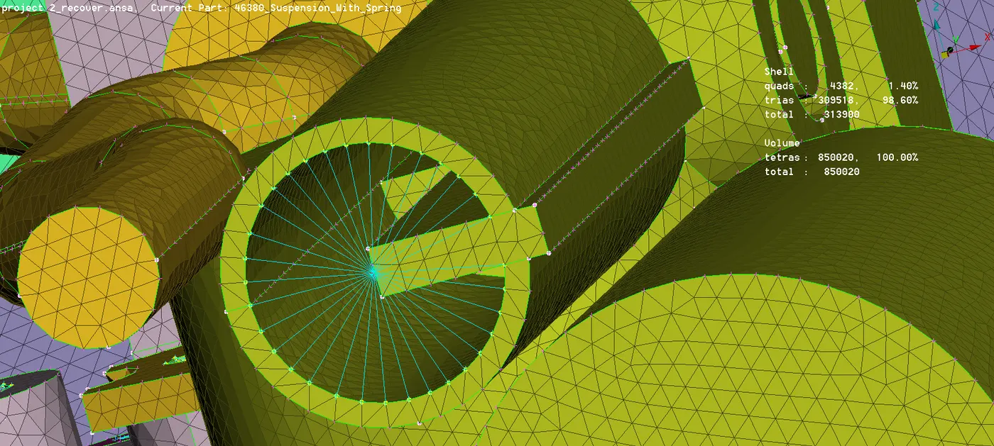
fig. RBE2 cluster connection
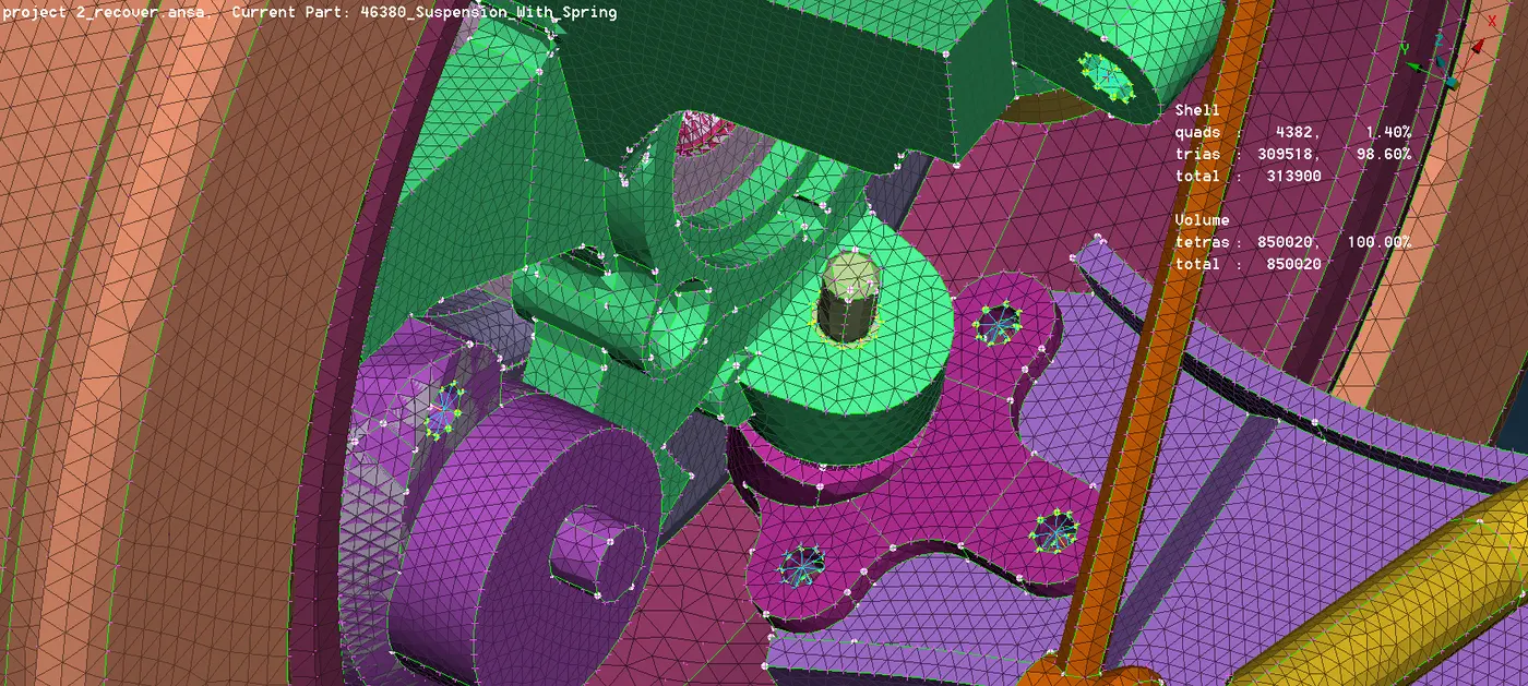
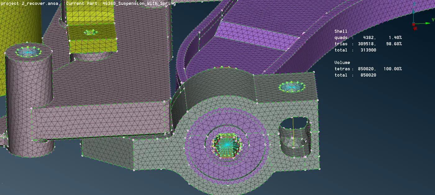
fig. RBE2 many node connection
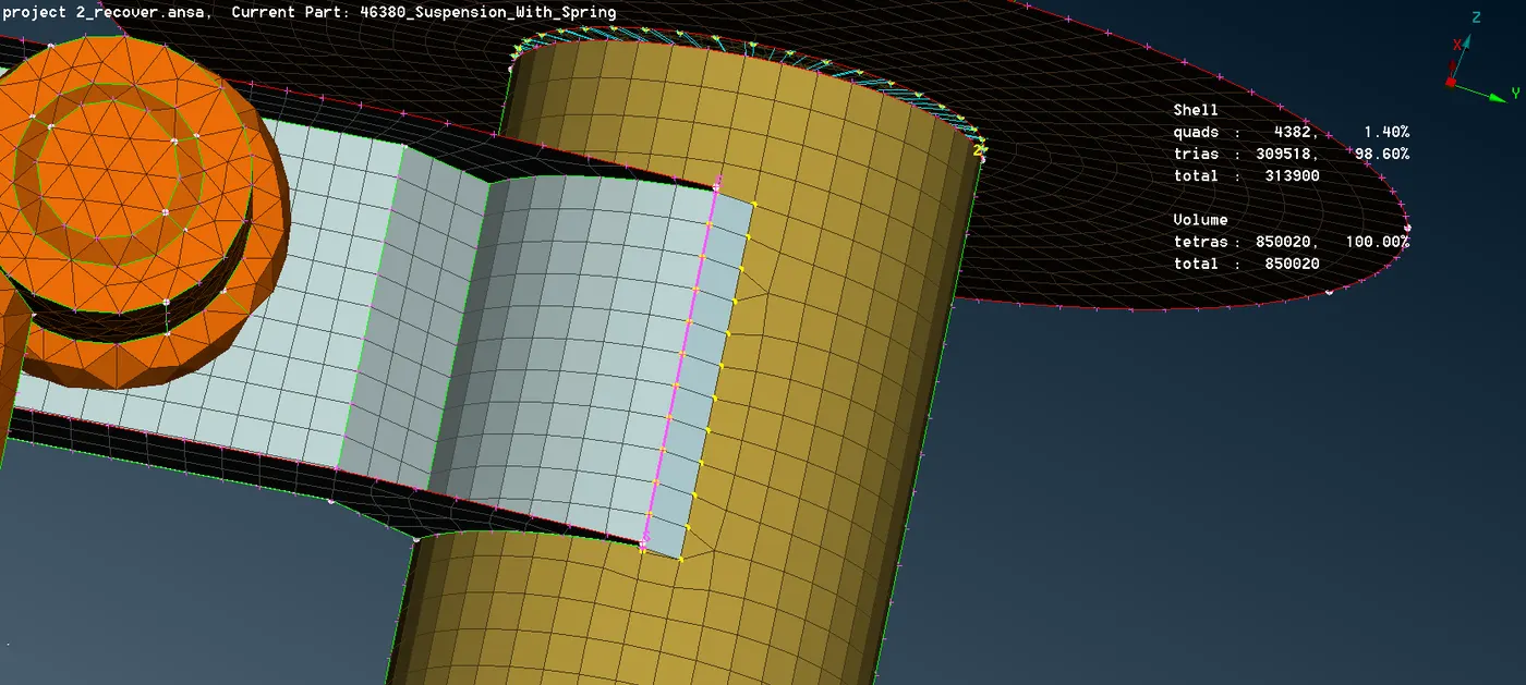
fig. seam weld connection
Modeling of coil spring using CBAR - Convert the spring into a single curve which should pass through the axis of it using the following steps
Topo module > Curve > Middle.
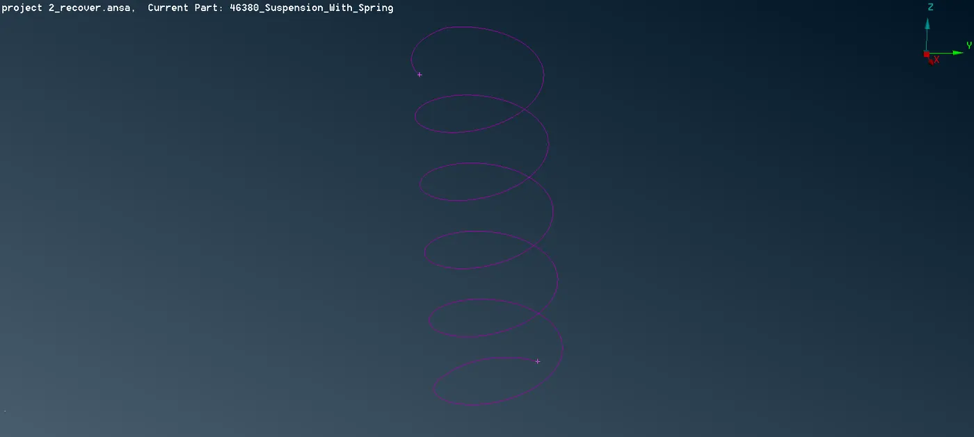
Using the connect option to convert the multiple curves into single curve by using the following steps.
Topo module > Curve > Connect > Multi.
Now with this curve in the middle of the spring select the CBAR option from the nastran deck. select curve
(Box) option from it and do a box selection on the curve

Now we need to input the average element length and after the box will as such and here we need to update the value of the diameter so that the area automatically calculated and PBAR PID is also created .
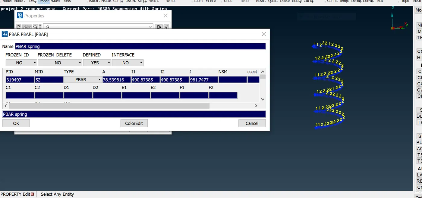
If we select the line element cross section > Draw mode > solids under the presentation parameter we can view the 2D mesh as a 3D mesh representation.
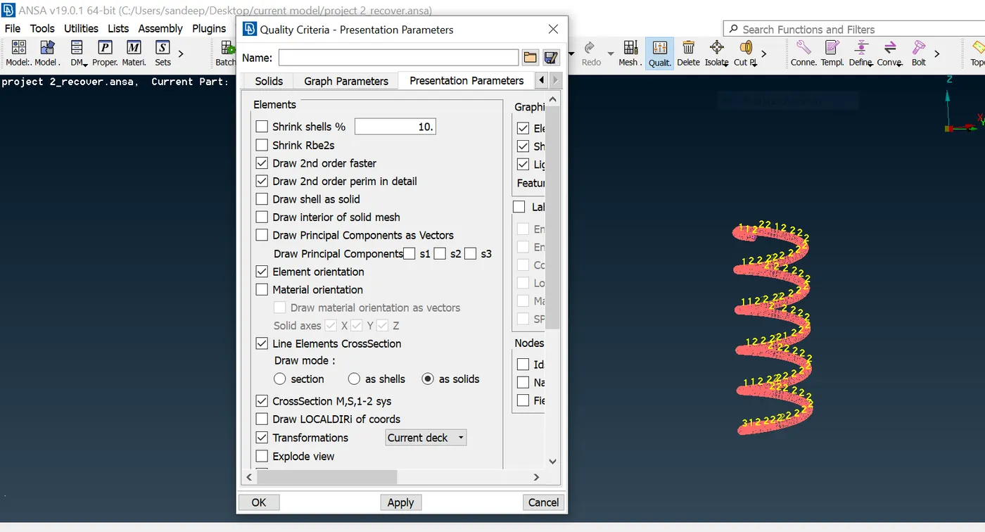
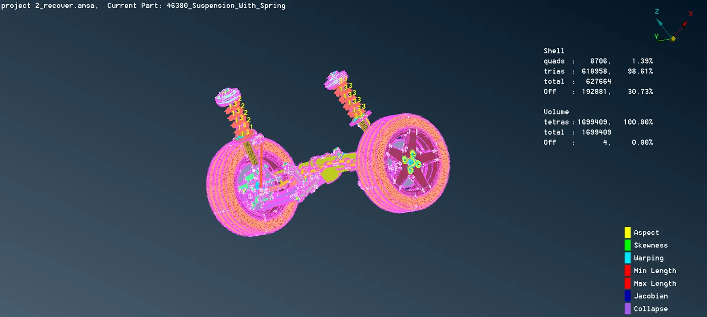
fig. Representation of suspension system
Learning outcome -
- Geometry checkup and clean up.
- 1D , 2D(shell) and 3D(solid) meshing.
- learn how to define volume and volume mesh.
- learn how to remove Tetra collapsed.
- learn different type of connections.
Conclusion - All the component of a suspension system are captured quite decently with tetra, ortho tetra or shell element (quad+trias) as per the given quality parameter.the sufficiently required connection are given with the RBE2 cluster and two node RBE2 .