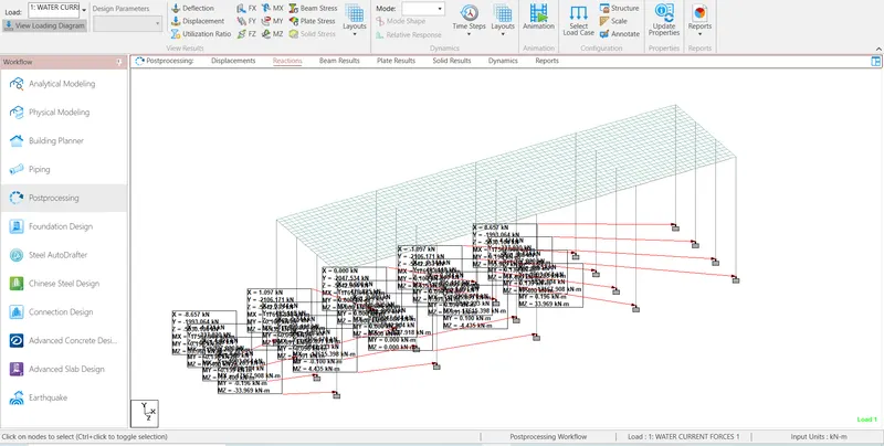
Project 2
AIM :– The aim of our is that, to Calculate the water current forces ,centrifugal forces, wave forces, snow loads, temperature loads, Barge Impact load fon the bridges and Create the model in Staad Pro and
analysis the Structure.
INTRODUCTION:–
- The Water Current Forces are the forces caused by the ocean current.
Whenever bridge piers are subjected to flowing water conditions or running water in the river, they are subjected to a force called water current force.
- The moving of a vehicle in a curve produces an outward pushing force from the bridge which exerts loads on the structural elements of the bridge called as the centrifugal forces.
- Wave load are caused by a distrurbance of the water surface. they develop due to disturbances likes winds, boat or ship wakes, or other forces, such as underwater landslides due to earthquakes. when the
wind blows on the , waves occur according to the intensity of the wind and generate a force on the any bridge substructure likes piers and abutments.
- Bridge structure are subjected to snow load when the bridge is located in a snowy region or cold climate countries.
- Temperature Load is Daily and Seasonal flutuations in shade air temperature, solar radiation, etc
effective bridge temperature- changes in overall temperature of bridge .
After a period, there will be a minimum and maximum with a range of effective temperature.
- Barge impact load is bridge crossing navigable channels of rivers, creeks and canals as well as shipping channels in port areas and open areas can be provided with nagigation spans.
The bridge details in given below.
The maximum crest elevation for the wave is 3 m.
The deck of the slab is supported by four I Girders.
Each I Girder is 1.6 m height with a top and bottom flange width of 2m.
The thickness of flange and web is 0.3m.
Assume constant r as 5.
Assume Cva as 3.
The Storm elevation is 8.5m.
Take Cr as 0.4.
The high flood level is 4 m above the Bottom of foundation level.
The span of the bridge is 10 m.
The mean velocity of the river is 2.5 m/s.
Width of carriage way is 9 m.
The bridge is subjected to a live load of Class 70R tracked vehicle.
Radius of curvature in the bridge is 2 m.
The design speed of the vehicles is 50 km/hr.
The size of the Pier is 1.2 x 1.2 m.
The width of deck slab is 10.5m.
The thickness of deck slab is 1.5 m.
The deck of bridge is flat with B <30 degree.
The depth of accumulation of snow is 1250 mm.
The Dead weight tonnage of Panamax vessel is 25000 DWT.
The Ship can accommodate maximum of 1500 containers.
Each container is of standard 6.1 TEU.
Assume the Settled Snow.
Assume the RC bridge with M40 grade to be constructed in Chennai.
Assume hydrodynamic coefficient is 1.25.
Assume V Barge impact speed is 17(m/s)
PROCEDUCE IN DETAIL:-
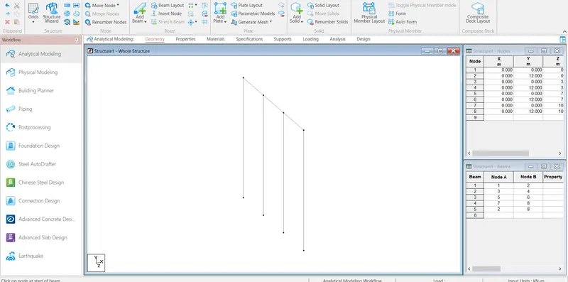
STEP1:- First create the node and select the add beam Command and create the beam
.
STEP2:- Then, Select the beam then go to the translation repeat Command and create the beam.
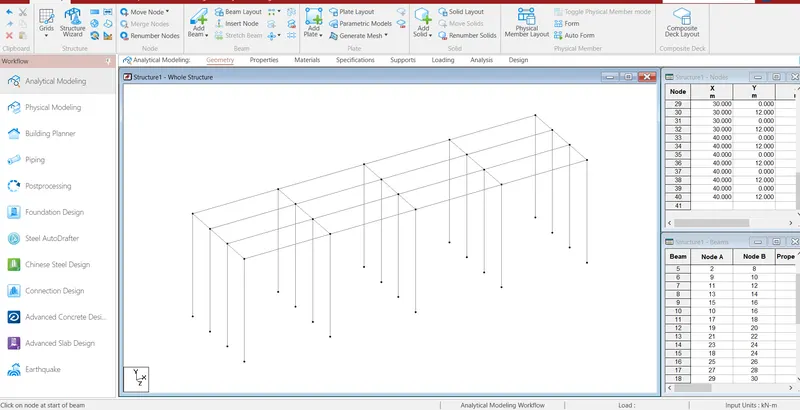
Step3:- After create the beam then select node cursor and select one node and go to the translation repeat command and create the node , then select add plates and create the plate then go to plates cursor
and select the plate and go to the translation repeat command and create the plate.
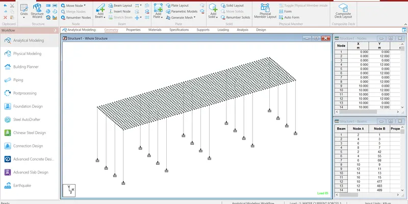
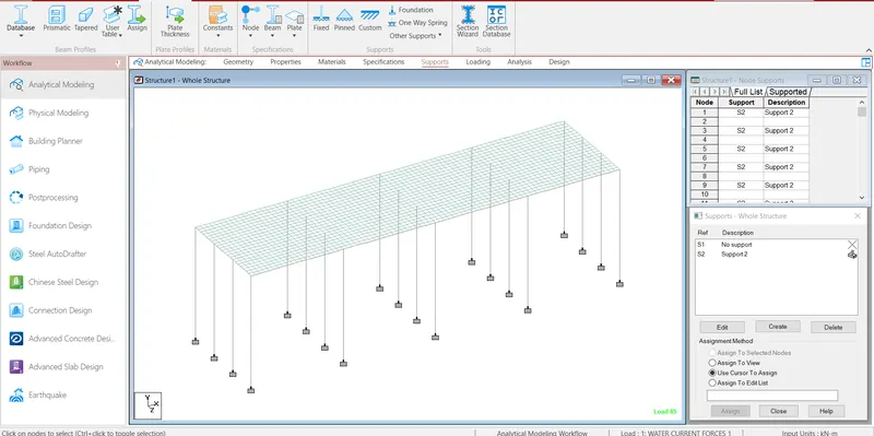
Step4:- After Create the model then go the support command create the fixed supports and assign the supports.
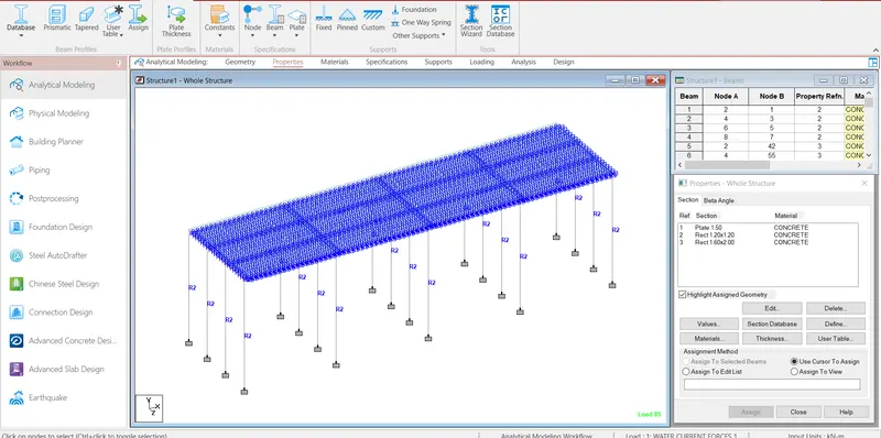
Step5:- After Create the support then go to the properties command and select geometry and assign the properties.
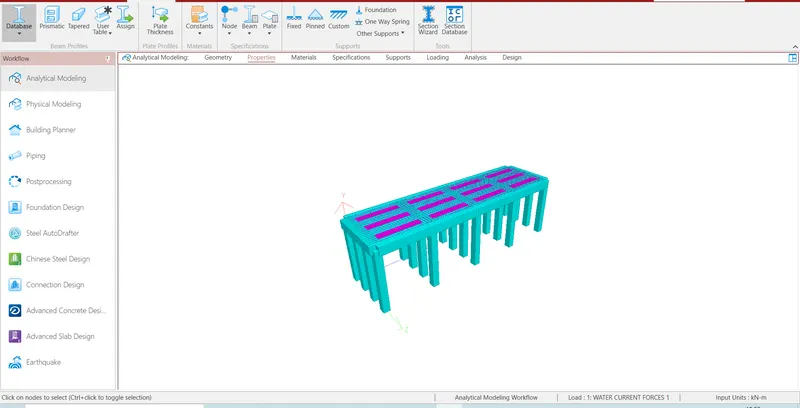
Then check how can see in 3d view. so select the all view and click right button and click the 3d rendering.
Step6:- Then Calculate Water current load as per IS Code 78-2000
P=52×Kv^2
Where
P = Intensity of Pressure due to water Current in kg/m^2
V =Maximum velocity of the current at the point where the pressure intensity is being calculated, in m/s
K= Constant based on the shape of piers
The value of shape constant of Square pier is 1.5 as per IS Code 78-2000 Section VII Table No 4 Page No 21.
Maximum velocity V,=`root` of 2`×Vmax
=`root` of 2`×2.5
=3.5355 m/s
P=52×1.5×3.5355^2
=974.9813 kN/m2
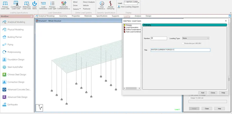
Step7:- After Calculate the Water Current Load then go to the Load cases Details and Add the Water Current Load.
Step8:- After add the water current load then click The water load , go to the member load and add the load both direction (GZ and - GZ).
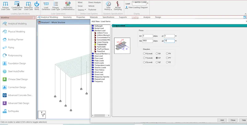
Step9:- After select the beam cursor and select the beam and create the load then assign the load.
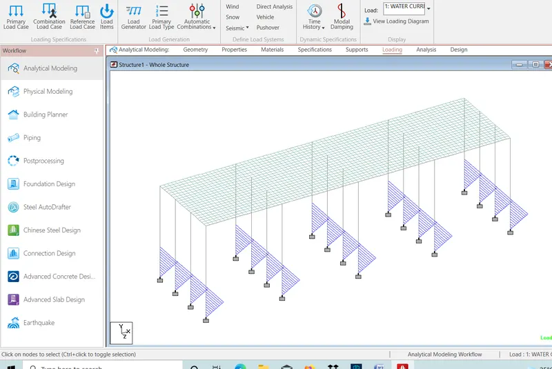
Step10:- After Calculate centrifugal forces as per IRC
C=W*V^2/127*R
C is Centrifugal force acting normal to traffic
w is live load
V is Design speed of vehicles using bridge in km/hr
R is Radius of curvature in m
Value of W is 70 kN for 70R tracked vehicle as per IRC
C=70*50*50/127*2
=688.97638 kN
Step11:- After Calculate the centrifugal forces then go to the vehicle definitions and define the load .
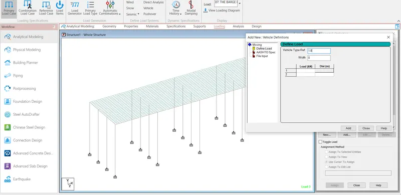
Step12:- After define the load then click Generate the load and generate load.
GENERATE LOAD= Span of bridge/Per Mesh Length of plate
=40/0.5
=80
Step13:- After generate the load then assign the load first of all to select the node cursor and select node and add the load.
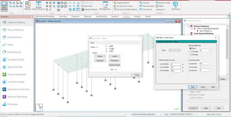
Step14:- After add the load then assign the load.
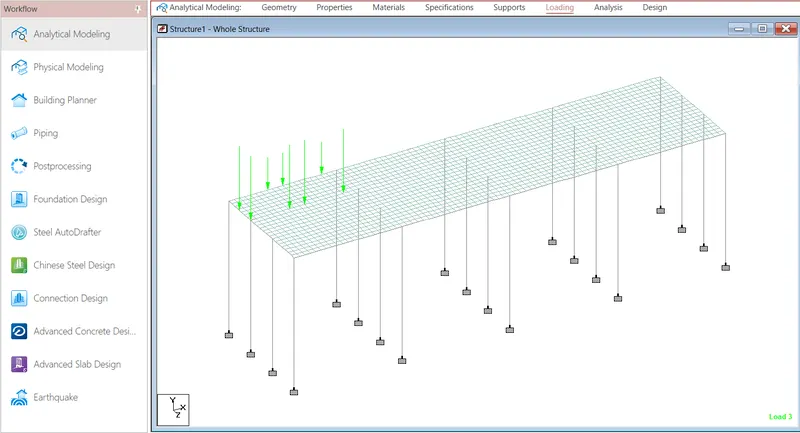
Step15:- Then Calculate the wave load as per IS code 4651
Maximumum crest ήmax=3 m
Zh= ήmax-Centroid of I girder
=3-(1.6/2)
=2.2m
Zv=ήmax- Elevation of bottom deck
=3-1.6
=1.4 m
Number of girder supporting bridge deck, N=4
Horizontal load, Fh =r*Zh*Ah
=5*2.2*3*40
=387kN
Max Horizontal load, Fhmax ={1 +Cr(N-1)}Cva*Fh
={1+0.4(4-1)}*3*387
=2089.8kN
Vertical load, Fv= r*Zv*Av
=5*1.4*(9*1.6/2)
=50.4kN
Max Vertical load Fvmax = Cva*Fv
=3*50.4
=151.2kN
Step16:- After Calculate the wave load then go to the Load cases Details and Add the wave load .
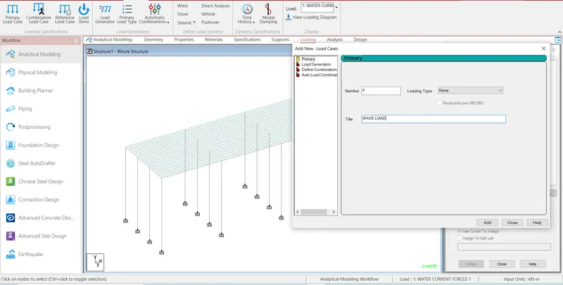
Step17:- After add wave load then click the wave load and click add then open the load items then click the nodal load and add the load Fy direction and Fz direction.
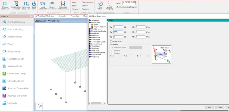
Step18:- After add the load select node cursor and select the node then create the load and assign the load.
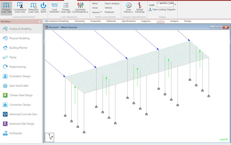
Step19:- Then calculate the snow load as per 875 IV Code.
Design Snow Load S=uSo
So is snow load on the ground
u is Shape Coefficient
So= Span of the Bridge* Depth of snow * Density of settled snow
Assume the Settled Snow
As per IS 875 Part IV code Density of settled snow is 2 -3kN/m3
We taken the value of Density of settled snow is 3 kN/m3
So=40*1.25*3=150 kN/m
As per IS 875 Part IV code value of Shape Coefficient for angle B<30 degree is,u = 0.8
S=u*So
=0.8*150
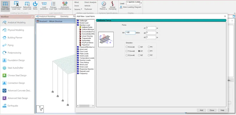
=120kN/m
Step20:- After Calculate the snow load then go to the Load cases Details and Add the snow load.
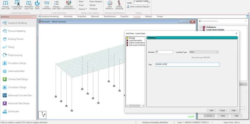
Step21:- After add snow load then click the snow load and click add then open the load items then click the member load then go to the uniform force and add the load GY direction .
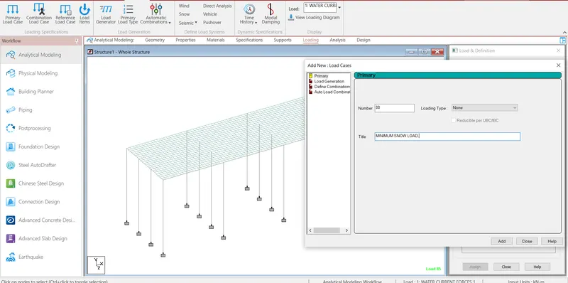
Step22:- After add the snow load then go to the Load cases Details and Add MINIMUM SNOW LOAD.
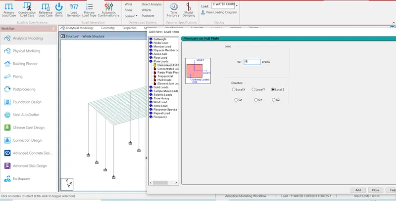
Step23:- After add minimum snow load then click the minimum snow load and click add then open the load items then click the plate load then go to the pressure on full plate and add the load according to IS
code on GY direction
.
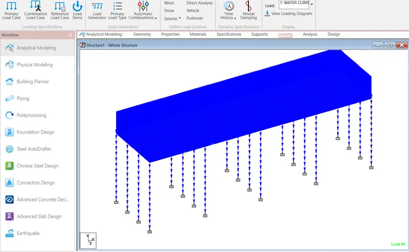
Step24:- After select the beam cursor and select the beam and create the snow load then assign the load.
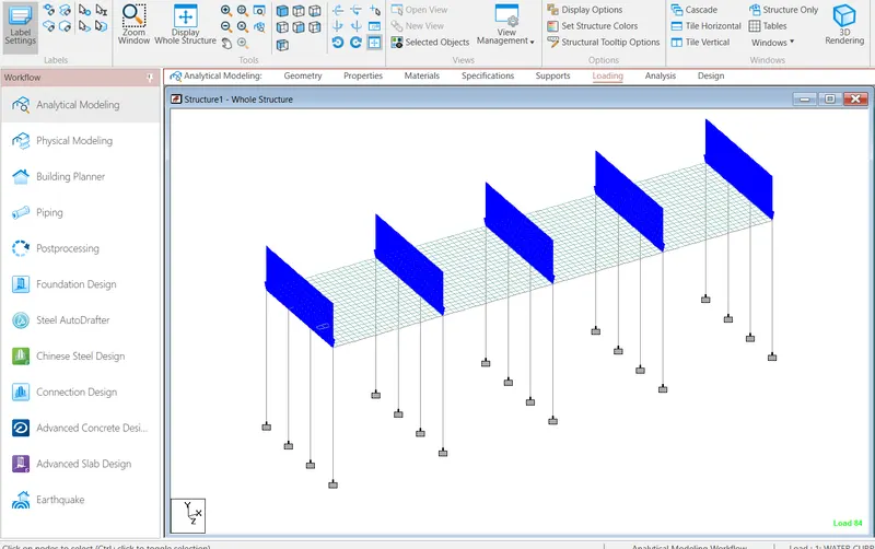
Step25:- After select the plate cursor and select the plate and create the minimum snow load then assign the load.
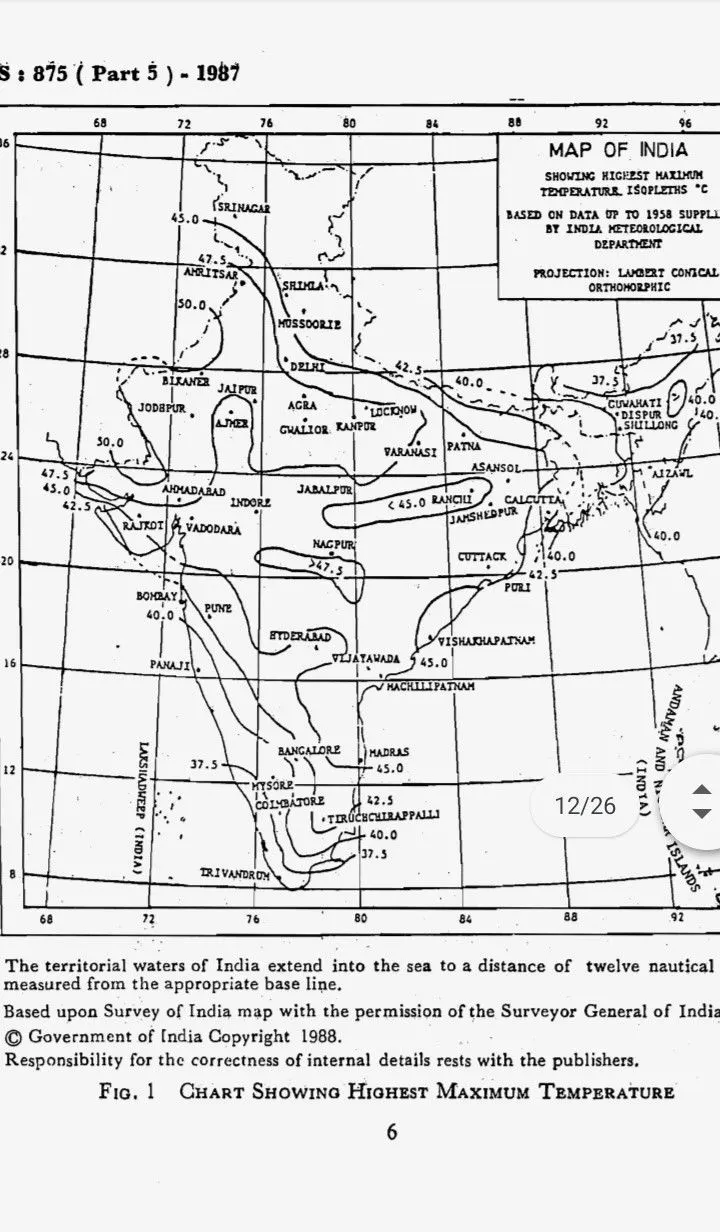
Step26:- Then Calculate the temperature load as per IS 875 Part V code
Maximum Temperature in the location as per IRC 6 Isotherm at the location =45degrees
Minimum Temperature in the location as per IRC 6 Isotherm at the location =12.5degrees
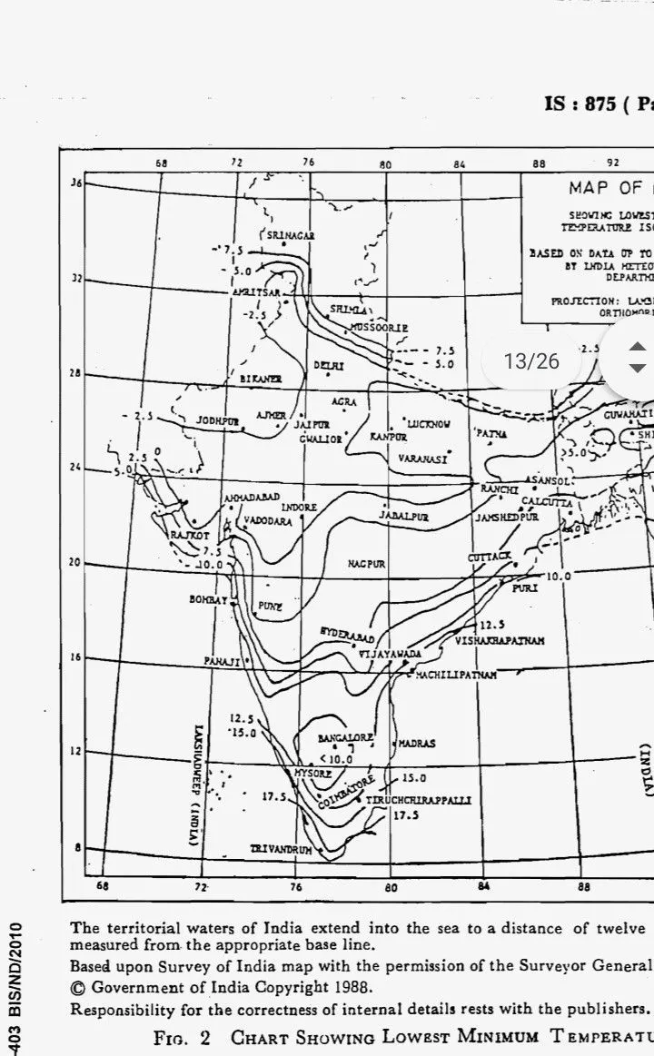
Effective temperature difference ={45-12.5)}/2 + 10
where 10 is critical load combination
Effective temperature difference= 26.25degrees
Stress Due to temperature = αTE
Where α is the coefficient of thermal expansion
T is effective temperature difference
Is Modulus of elasticity of material
The coefficient of thermal expansion of Reinforced concrete is taken as 11.27 *10^-6 degree per centigrade
Modulus of elasticity of Reinforced concrete is 5000(fck)^(1/2)Stress
Stress Due to temperature =11.27*^10-6*26.25*5000(40)^1/2
=9.35kN/m2
Max permissible stress =2/3 *0.7 *fck^(1/2)
=2/3*0.7*40^0.5
=2.95 kN/m2
Hence , the Stress are restricted to 3kN/m2
Maximum Temperature = 45 degrees
Minimum Temperature =12.5 degrees
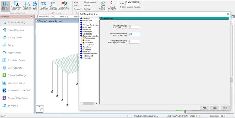
Positive temperature differenceTemperature at top = 45 degrees
Temperature at Bottom = (2.1/17.8)*45=5.30 degrees
Step27:- After Calculate the temperature load then go to the Load cases Details and Add the temperature load.
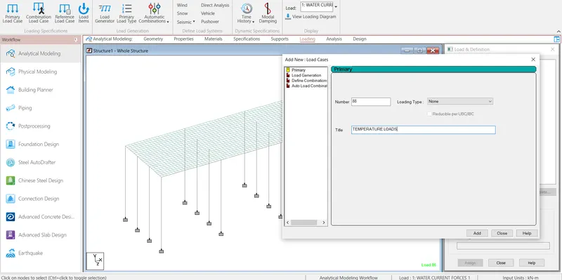
Step28:- After add temperature load then click the temperature load and click add then open the load items then click the temperature load then go to the temperature and add temperature load
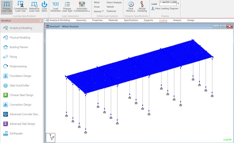
Step29:- After add temperture load then click the assign to view and assign the load.
Step30:- Then Calculate the Barge impact load as per Inland Waterway Authority of India (IWAI)
KE= 500*Ch*W*V^2
Where W is Barge displacement tonnage (T)
V Barge impact speed (m/s)
Ch is hydrodynamic coefficient 1.25
V=17 m/s
KE= 500*1.25*25000*17^2
KE=451562KN-m
Barge damage depth,
aB=3100*{(1+1.3*10^-7 KE)^0.5-1}
Where aB is Barge blow damage depth (mm)
aB=3100*{(1+1.3*10^-7*4.51562*10^9)^0.5-1
=72072.9611mm
Barge collision impact force,
PbThe barge collision impact force shall be determined based on the following equations.
For ab <100mm, Pb= 6.0*10^4*(aB), in N
For ab >=100mm,
Pb= 6.0*10^6+1600*(aB), in N
Then
case 2 is following Pb =0.6*10^6+1600*72072.9611
=115916.738kN
Step31:- After Calculate the Barge load then go to the Load cases Details and Add the Barge load.
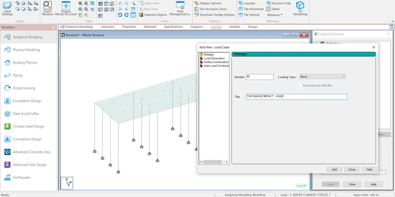
Step32:- After add Barge load then click the Barge load and click add then open the load items then click the member load and go to the uniform force and add the load -GY direction.
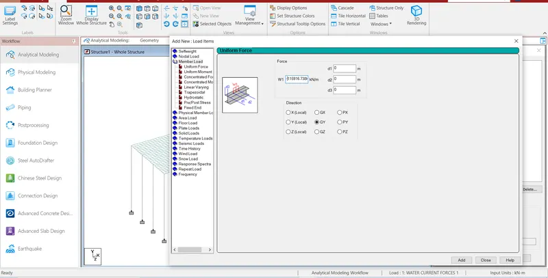
Step33:-After select the beam cursor and select the beam then assign the Barge load.
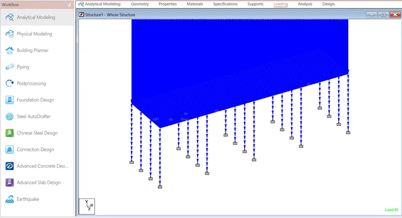
Step34:- After all loads create and assign the load on the model then slave the file and click the run analysis.
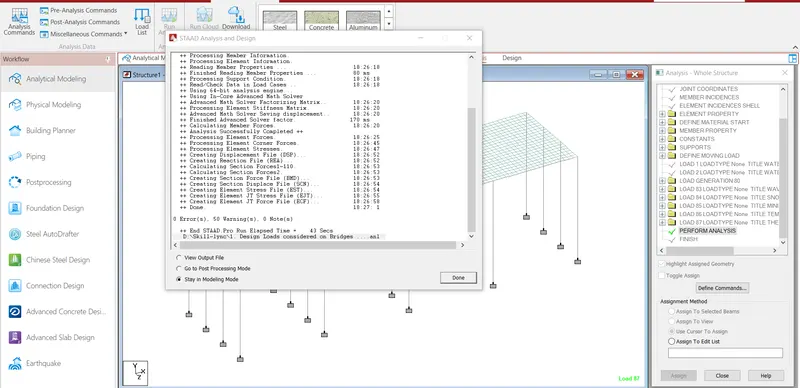
RESULT:- 974.9813 kN/m2 due to Water current load, 688.97638 kN due to centrifugal forces ,Max Horizontal load 2089.8kN Max and Vertical load 151.2kN due to wave forces, 120kN/m due to snow loads,
Stress Due to temperature 9.35kN/m2 and Max permissible stress due to temperature 2.95 kN/m2, 115916.738kN due to Barge Impact load is acting in the bridge.
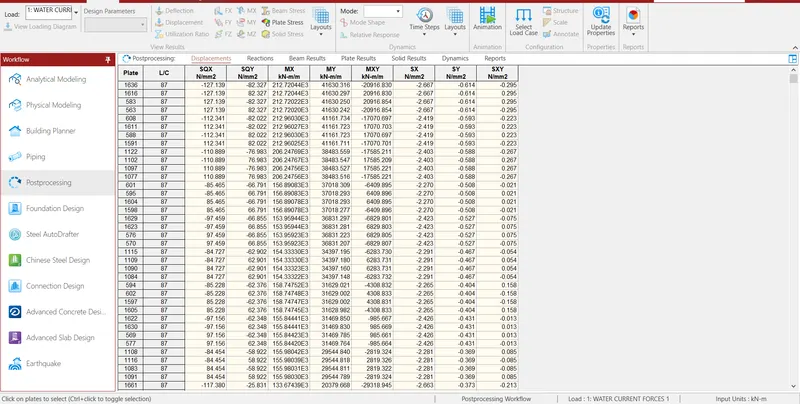
Step35:- First of all check to plate stress into the model due to load, and then click plate cursor before click plate stress. The maximum bending moment due to load in 1636 plate, and minimum bending
moment in X the direction due to load in 2125 plate.
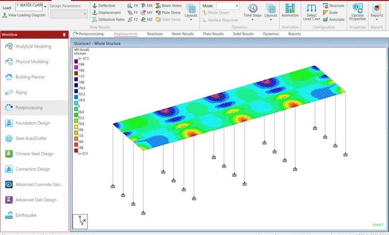
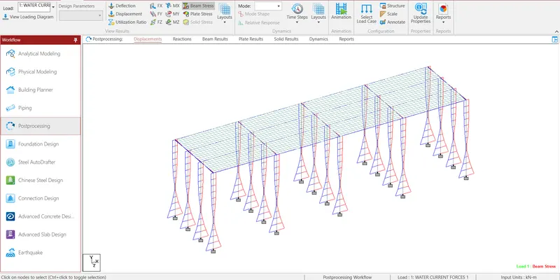
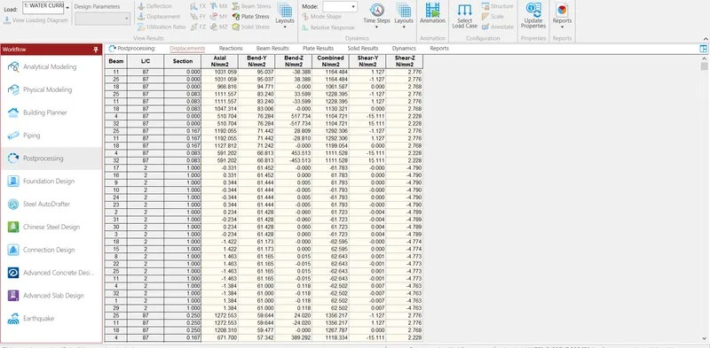
Step36:- then all check to beam stress into the model due to load, and then click beam cursor before click beam stress. The maximum bending moment in Y the direction due to load in 11 beam, and minimum
bending moment in Y the direction due to load in 22 beam.
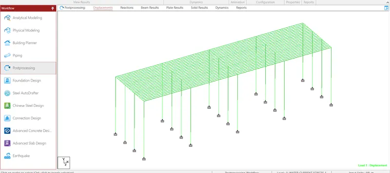
Step37:- Then all check to the Deflection into the model due to load, and then click beam cursor before Deflection.
Step38:- Then check the value of reactions into the piers.