Preprocessing of Vehicles Suspension Assembly using ANSA Workbench
VEHICLE’S SUSPENSION SYSTEM ASSEMBLY
Aim:To Mesh the Component both 2D meshing and Solid meshing cinsidering all the given quality criteria and to define the volume and do the volume meshing and also to give the connection whereever required.
Overview of Vehicle Suspension System:
When most people think of automotive performance, they think of power, the need for speed, the roaring sound of the engine, and how fast the vehicle will go from zero to 60 miles per hour. However, all this power and speed is useless if the driver is unable to control the vehicle and is not comfortable while driving. Therefore, the automotive suspension is a crucial vehicle system.
The primary functions of the suspension system include maximizing the contact between the tires and the road surface, providing steering stability and good handling, evenly supporting the weight of the vehicle (including the frame, engine, and body), and ensuring the comfort of passengers by absorbing and dampening shock. Your vehicle’s suspension system works hard to withstand a considerable amount of stress compared to other major vehicle systems 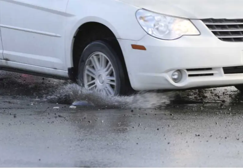
The suspension system consists of tires, the air in the tires, springs, shock absorbers, struts, arms, bars, linkages, bushings, and joints. The suspension system components are located between the frame of the vehicle and the road. Well-tuned suspensions will absorb bumps and other imperfections in the road allowing the people inside the vehicle to travel safely and comfortably.
The tires and the amount of air in the tires are a fundamental part of the suspension system. The tires are the only part of the vehicle that come in contact with the road. This means they have to steer and put power to the ground simultaneously while also being responsible for stopping the vehicle. The suspension system requires the wheels and tires to travel up and down to absorb the shock from bumps. The rubber tires and air in the tires also soften the ride over hard surfaces and conform to slightly uneven and rough surfaces.
Shock absorbers, also known as shocks, are hydraulic oil-filled cylinders that force the suspension to compress and decompress at a consistent rate to prevent the springs and vehicle from bouncing up and down. Shocks are velocity-sensitive, meaning they are smoother when dealing with light bumps and put up more resistance to big bumps. The primary purpose of the shock absorbers is to control spring and suspension movement and make sure tires maintain contact with the road.
How Car Suspension Works?
The job of a car suspension is to maximize the friction between the tires and the road surface, to provide steering stability with good handling and to ensure the comfort of the passengers. In this article, we'll explore how car suspensions work, how they've evolved over the years and where the design of suspensions is headed in the future.
If a road were perfectly flat, with no irregularities, suspensions wouldn't be necessary. But roads are far from flat. Even freshly paved highways have subtle imperfections that can interact with the wheels of a car. It's these imperfections that apply forces to the wheels. According to Newton's laws of motion, all forces have both magnitude and direction. A bump in the road causes the wheel to move up and down perpendicular to the road surface. The magnitude, of course, depends on whether the wheel is striking a giant bump or a tiny speck. Either way, the car wheel experiences a vertical acceleration as it passes over an imperfection.
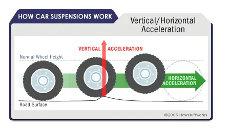
Without an intervening structure, all of wheel's vertical energy is transferred to the frame, which moves in the same direction. In such a situation, the wheels can lose contact with the road completely. Then, under the downward force of gravity, the wheels can slam back into the road surface. What you need is a system that will absorb the energy of the vertically accelerated wheel, allowing the frame and body to ride undisturbed while the wheels follow bumps in the road.
Car Suspension Parts:
The suspension of a car is actually part of the chassis, which comprises all of the important systems located beneath the car's body. These systems include:
- The frame - structural, load-carrying component that supports the car's engine and body, which are in turn supported by the suspension
- The suspension system - setup that supports weight, absorbs and dampens shock and helps maintain tire contact
- The steering system - mechanism that enables the driver to guide and direct the vehicle
- The tires and wheels - components that make vehicle motion possible by way of grip and/or friction with the road
So the suspension is just one of the major systems in any vehicle.
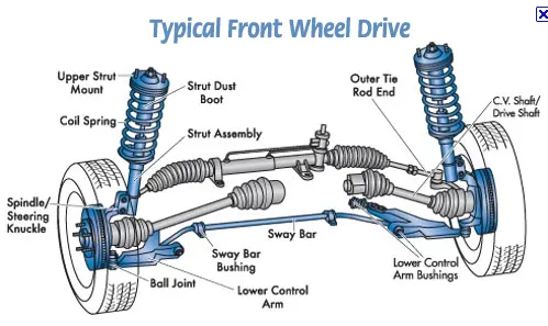
The three fundamental components of any suspension are:
1)Springs
Springing systems are based on one of four basic designs:
- Coil springs - This is the most common type of spring and is, in essence, a heavy-duty torsion bar coiled around an axis. Coil springs compress and expand to absorb the motion of the wheels.
- Leaf springs consist of several layers of metal (called "leaves") bound together to act as a single unit.
- Torsion bars use the twisting properties of a steel bar to provide coil-spring-like performance. This is how they work: One end of a bar is anchored to the vehicle frame. The other end is attached to a wishbone, which acts like a lever that moves perpendicular to the torsion bar. When the wheel hits a bump, vertical motion is transferred to the wishbone and then, through the levering action, to the torsion bar. The torsion bar then twists along its axis to provide the spring force.
- Air springs consist of a cylindrical chamber of air positioned between the wheel and the car's body, use the compressive qualities of air to absorb wheel vibrations. The concept is actually more than a century old and could be found on horse-drawn buggies.
2)Dampers
-
Unless a dampening structure is present, a car spring will extend and release the energy it absorbs from a bump at an uncontrolled rate. The spring will continue to bounce at its natural frequency until all of the energy originally put into it is used up. A suspension built on springs alone would make for an extremely bouncy ride and, depending on the terrain, an uncontrollable car.
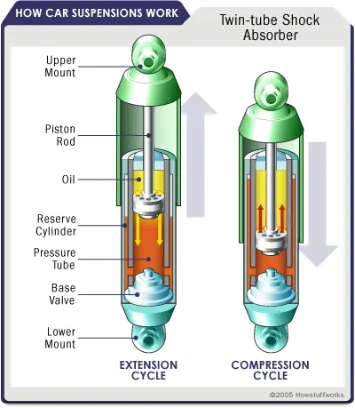
Enter the shock absorber, or snubber, a device that controls unwanted spring motion through a process known as dampening. Shock absorbers slow down and reduce the magnitude of vibratory motions by turning the kinetic energy of suspension movement into heat energy that can be dissipated through hydraulic fluid. To understand how this works, it's best to look inside a shock absorber to see its structure and function.
- A shock absorber is basically an oil pump placed between the frame of the car and the wheels. The upper mount of the shock connects to the frame (i.e., the sprung weight), while the lower mount connects to the axle, near the wheel (i.e., the unsprung weight). In a twin-tube design, one of the most common types of shock absorbers, the upper mount is connected to a piston rod, which in turn is connected to a piston, which in turn sits in a tube filled with hydraulic fluid. The inner tube is known as the pressure tube, and the outer tube is known as the reserve tube. The reserve tube stores excess hydraulic fluid.
3)Anti-sway bars.
-
Another common dampening structure is the strut — basically a shock absorber mounted inside a coil spring. Struts perform two jobs: They provide a dampening function like shock absorbers, and they provide structural support for the vehicle suspension. That means struts deliver a bit more than shock absorbers, which don't support vehicle weight — they only control the speed at which weight is transferred in a car, not the weight itself.Because shocks and struts have so much to do with the handling of a car, they can be considered critical safety features. Worn shocks and struts can allow excessive vehicle-weight transfer from side to side and front to back. This reduces the tire's ability to grip the road, as well as handling and braking performance.
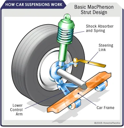
Types of suspension:
1)Dependent Suspension:
If a solid axle connects the rear wheels of a car, then the suspension is usually quite simple — based either on a leaf spring or a coil spring. In the former design, the leaf springs clamp directly to the drive axle. The ends of the leaf springs attach directly to the frame, and the shock absorber is attached at the clamp that holds the spring to the axle. For many years, American car manufacturers preferred this design because of its simplicity.
The same basic design can be achieved with coil springs replacing the leaves. In this case, the spring and shock absorber can be mounted as a single unit or as separate components. When they're separate, the springs can be much smaller, which reduces the amount of space the suspension takes up.
2)Independent Suspension:
If both the front and back suspensions are independent, then all of the wheels are mounted and sprung individually, resulting in what car advertisements tout as "four-wheel independent suspension." Any suspension that can be used on the front of the car can be used on the rear, and versions of the front independent systems described in the previous section can be found on the rear axles. Of course, in the rear of the car, the steering rack — the assembly that includes the pinion gear wheel and enables the wheels to turn from side to side — is absent. This means that rear independent suspensions can be simplified versions of front ones, although the basic principles remain the same.
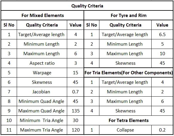
Given Quality Criteria:
Procedure:
1)Import .IGS File of Suspension Assemblu in to ANSA Workbench
2)Separation of Parts and Assign New Individual PID.
3)Geometrical Cleanup and Topology
4)Defeaturing
5)Surface Meshing
6)Defining the Volume
7)Volume Meshing
8)Check for Quality Criteria
Procedure:
1)Import .IGS File of Suspension Assemblu in to ANSA Workbench
- Import the Suspension Assembly.IGS into the ANSA Workbench as shown in fig 1.1
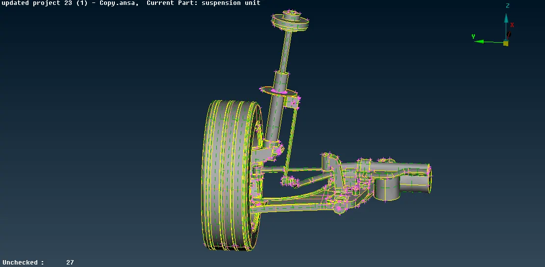
fig 1.1 .IGS file of Suspension Assembly
- Change the Mode to Topo
 and Entity
  .
. - Set the proper orientation as shown
- Change the perimeter length to 1(MESH>PERINETER>LENGTH) as shown in fig 1.2
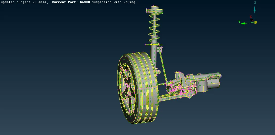
Fig 1.2 Length Change to 1mm
2)Separation of Parts and Assign New Individual PID.
Each Component is separated from the Assembly and give the Sepearate PID individually as shown in fig 2.1
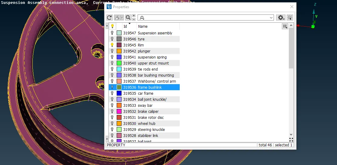
Fig 2.1 Assigning PID to the Component
3)Geometrical Clean up and Topology
- Check all the geometry errors in the checks manager(Checks>Geometry>Execute) as shown in Fig 2.1
- Eliminate All the Triple Cons and Cracks between 2 Surafces by releasing thr triple cons and applying topo as shown in Fig 2.2
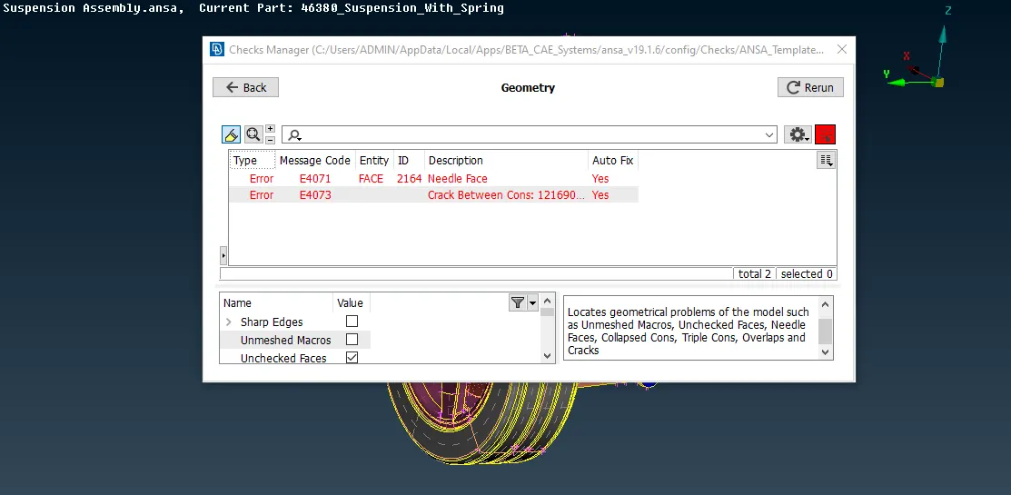
Fig 2.1 Geometrical Errors
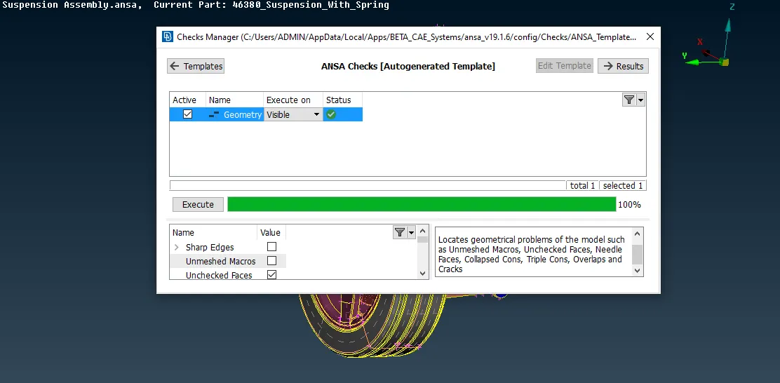
Fig 2.1 Geometrical Cleaned Up Component
Now the Component is error free and is ready for mid surface extraction and Surface Meshing.
3)Defeaturing
In this step Change the Perimter Lenghth withe reference to the Given Quality Criteria i.e. Average Length=1mm in this Component.(Mesh Mode>Perimeters>Length).Delete all the unwanted Cons.Faces and Ensure the distance between the Two Cons are more than given target length.
4) Extraction of Mid Surface
- Check for the Component for which we need to extract the Mid Surface( Thickness Less than 5mm) as shown in fig 4.1
-
Mid surface has taken manually as the component has varying thickness which is too less which causes quality criteria failure in the auto mid.
-
Manual mid surface is taken by using 2 commands
a)Offset Command (Topo Mode >Faces
 >Offset
 ) in which we have to select the faces for which we need the mid surface and later we need to input the offset value(Half the thickness).Negetive and positive signs indiactes the direction in which the value need to offset.
b)Middle Command (Topo Mode>Faces>Middle ) in which we need to selct the 2 faces for which we need mid surface and on confirmation it will automatically generate the midsurface.
- In this model the thickness is uniform and we are taking the mid surface by Offset Command as shown in the fig 4.2.After Entering the Offset Value Click Ok.Mid Surface will be generated.
- To Check he Mid Surface from the Parent Model,Enable PID Region
 and using INOT
  command hide the parent object.Thus Visible model on the screen will be your Mid Surface.
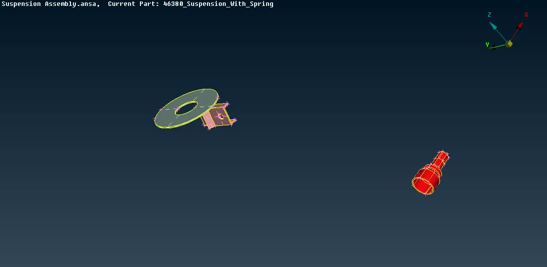
fig 4.1 Components applicable for Mid Surface Extraction
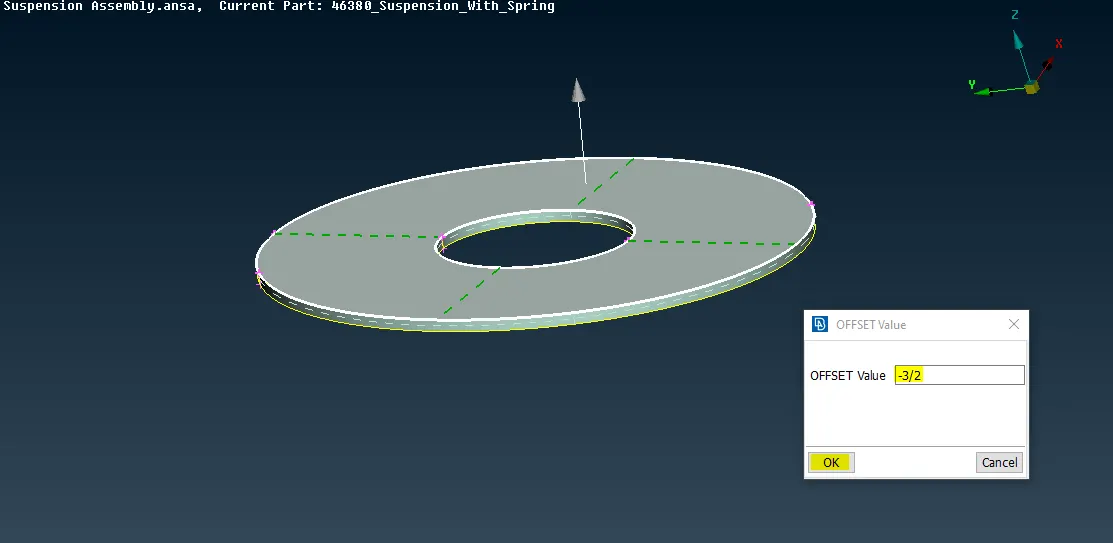
fig 4.2.1 Selecting Faces for Offset
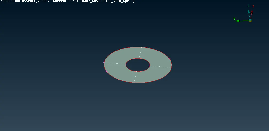
fig 4.2.2 Mid Surface
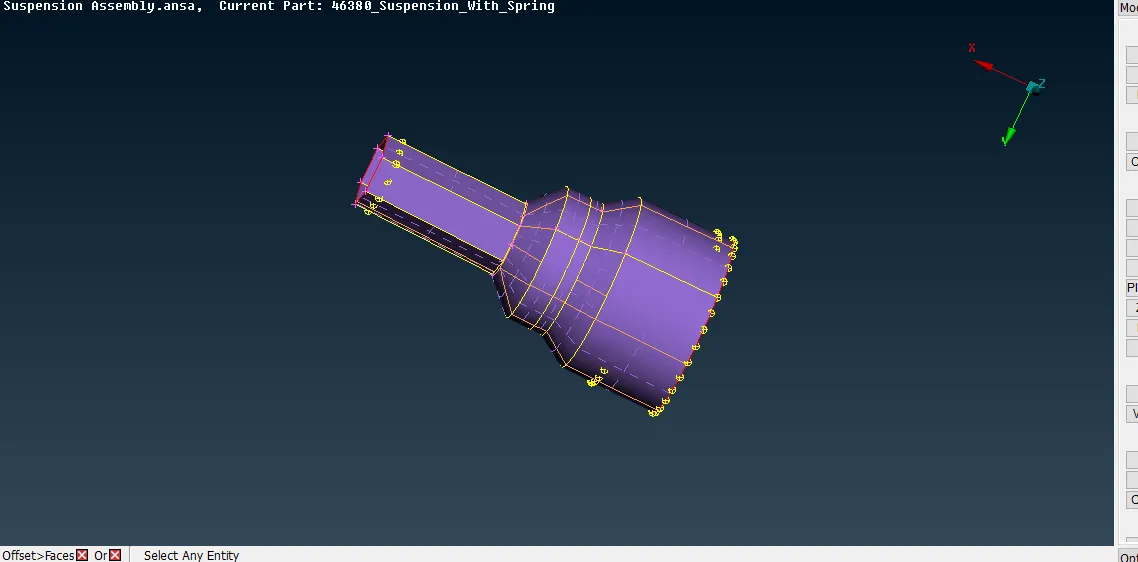
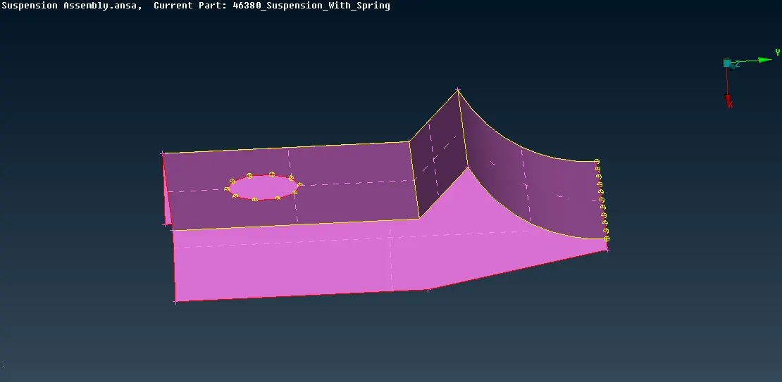
Like wise all the Mid Surface has to be extracted as shown in fig 4.2.3
5)Surface Meshing
- Switch from Topo Mode to Mesh Mode

- Enter the Mesh Prameters (Utilities>Mesh Parameters
 ) as in fig 4.1 and Quality Criteria(Utilities>Mesh Parameters
 ) as in fig 4.2
 - For the Solid Component Use the Ortho Tria for curved surfaces and Normal Trias for Flat Surface
- Please make sure that the quality criteria is different for Tyre and Rim .refer the Quality chart above
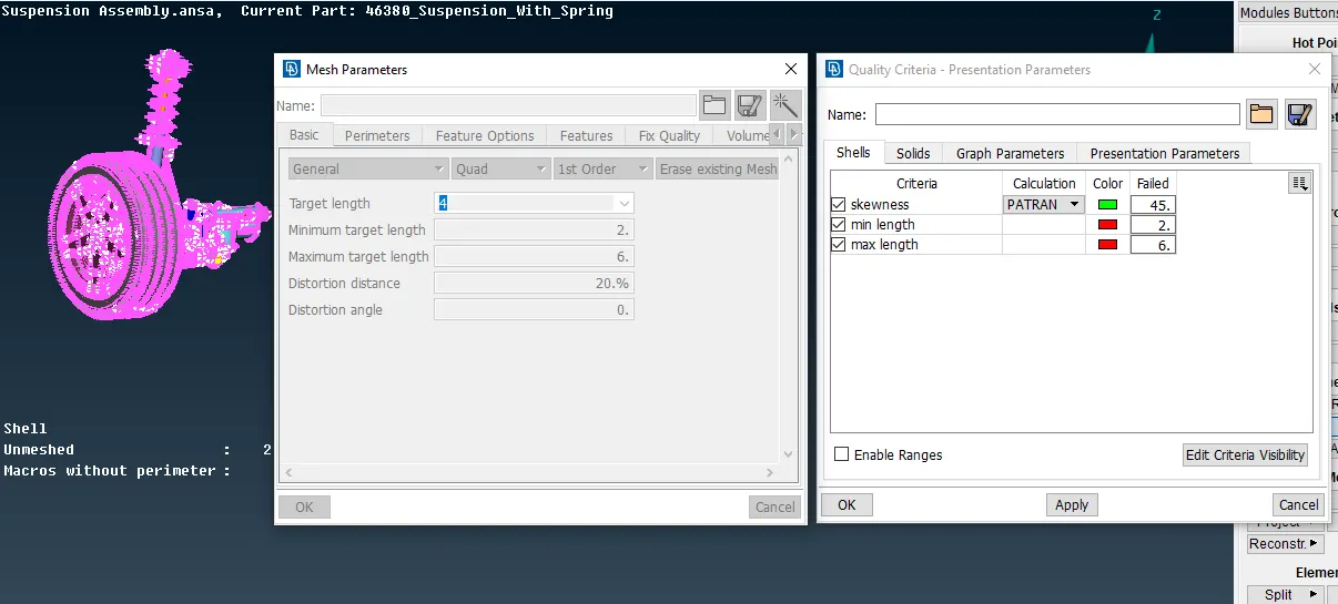
Fig 5.1 Quality Criteria and Mesh Parameters Tab
- Start the Meshing on the Surface.(Mesh Mode>Mesh Generation>Spot Mesh) fig5.2 shown below.
- Avoid Kinks and Dinks while meshing.
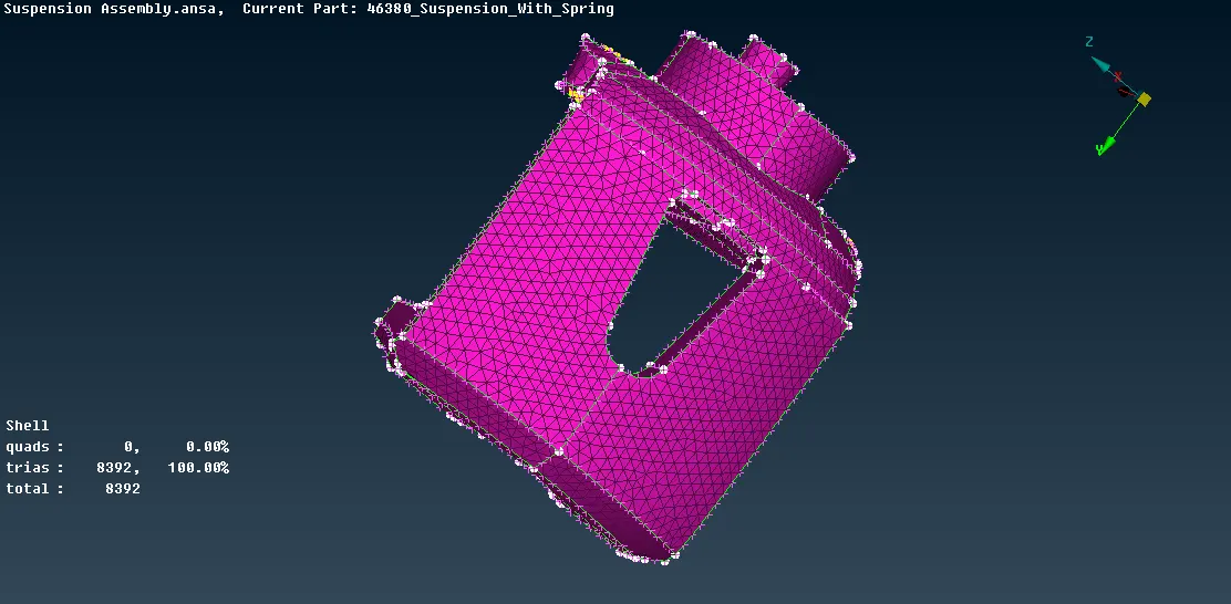
fig5.2 Spot Mesh
Like was all component should Meshed Individually and the pictures are mentioned below in fig 5.3
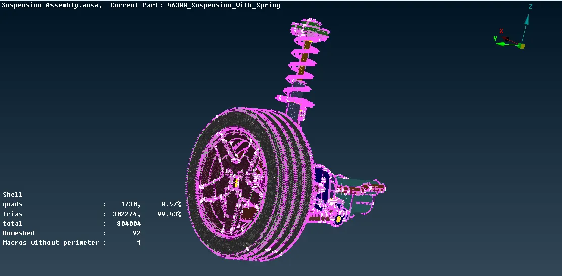
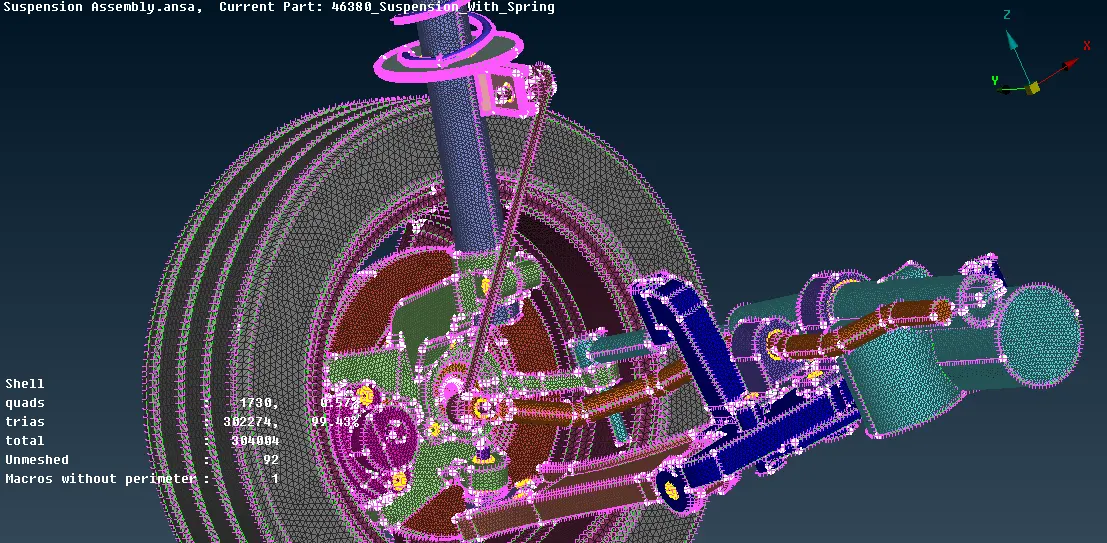
fig 5.3 Surface Meshing
6)Defining the Volume:
- Go to Voume Mesh Mode
 from the Mesh Mode
 - Define the Volume of the Component(Volumes
 >Define
 >Manual/Auto) as shown in fig 6.1
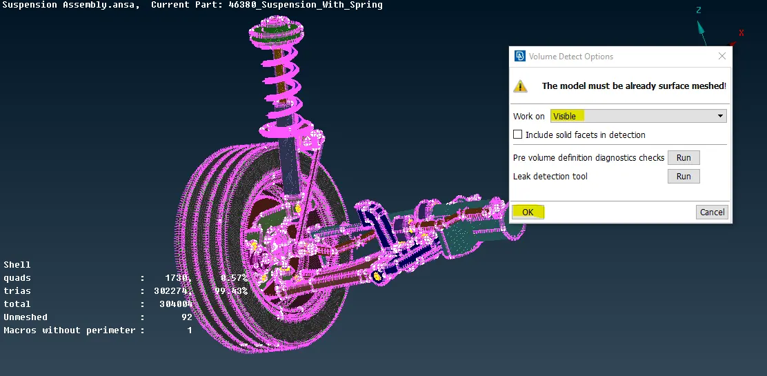
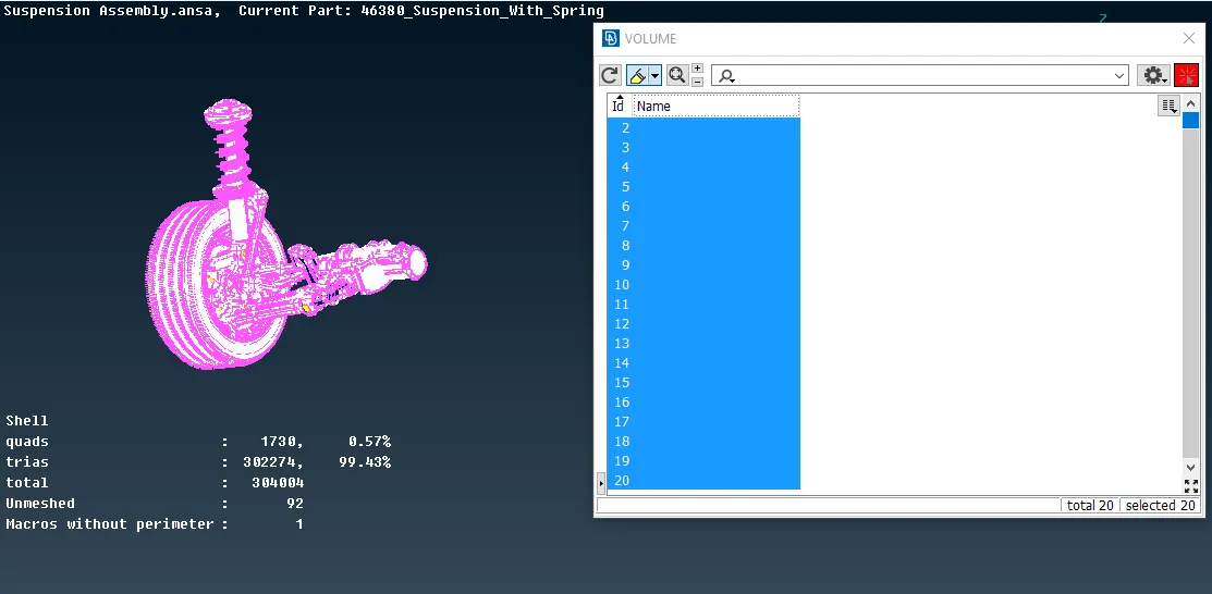
fig 6.1 Defining Volume..
7)Volume Meshing:
Volumetric meshes are a polygonal representation of the interior volume of an object. Unlike Polygonal Meshes, which represent only the surface as polygons, volumetric meshes also discretize the interior structure of the object.
Quality Checks for Tetra Meshing
- Tet Collapse
When auto-generating a mesh in a complex or invalid geometry. A tetra element, which seems as thin as a planar element, will be often generated. This type of the element is called as a collapsed tetra, and this option enable to check for such a collapsed element.
- Once after defining the Volume we need to mesh the Volume.(Unstructured Mesh
 >Tetra Rapid/FEM>Select the Entity) as shown in fig 7.1.
 - Check for the Tet Collapse Error.
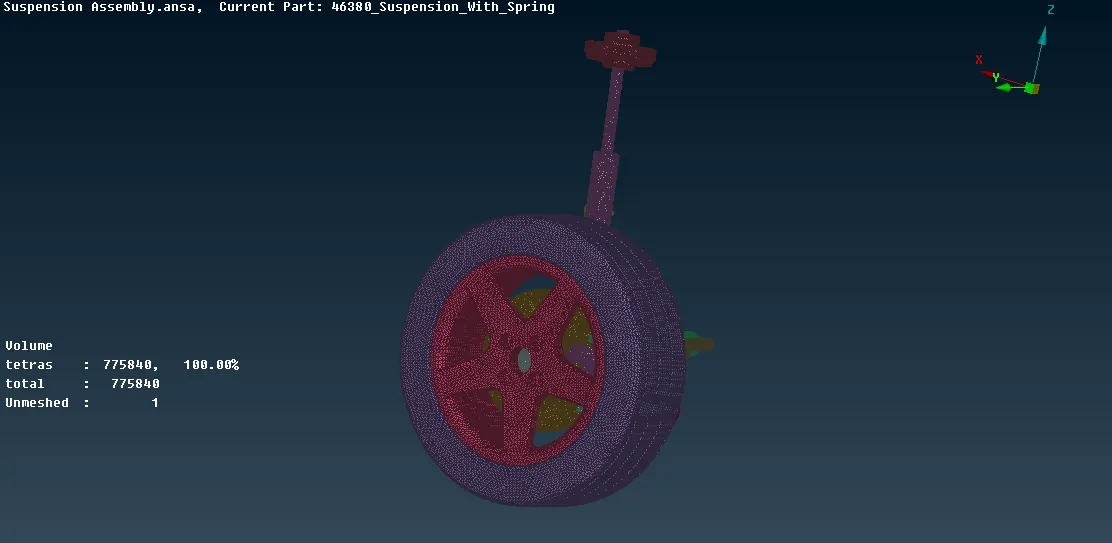
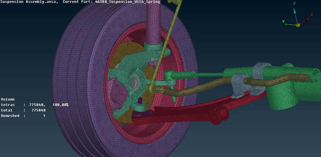
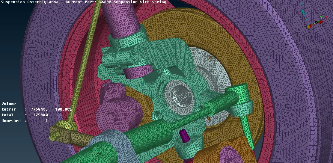
Fig 7.1.Volume Meshing
8)Connections
After the 1D and 2D Meshing we need to make the assembly Rigid by giving the suitable connections wherever required.
In this model we are goin to give the Connection in the NASTRAN Deck
The Nastran group of elements often described as the "Rigid elements" are very usefull engineering analysis tools. "Rigid Element" is a slight misnomer, but the term is still used to describe the most commonly used items: the "RBE2" and the "RBE3".
- Firstly, what are rigid elements, and why might you want to use them?
A rigid element is a link from one node to one or more other nodes, where the motion of the node(s) is governed by the "degrees of freedom" you choose to connect. A rigid element is actually a constraint equation rather than an actual element, but for practical purposes that matters little, except for the tips to avoid common errors with rigid elements
Example:
To model the dynamic behaviour of a vehicle, the engine can be modelled as a mass element connected by an RBE2 rigid element to the engine's multiple mounting locations.This makes the reasonable assumption that the engine is "very stiff" compared to the body structure and so the engine does not need to be modelled in detail.The mass is located at the centre of gravity of the engine, and the rigid element links the engine mass to the rubber mounts (eg. springs or bushes) whose stiffnesses are typically much more relevant
- What is the difference between RBE2 and RBE3 elements?
Both elements looks the same, in that they have a single node connected to one or multiple other nodes. The difference is that the RBE2 element adds (infinite) stiffness to the structure, while RBE3 elements "distribute forces" around the connected nodes, without adding any stiffness.
For an RBE2 rigid element, the single node is the "independent node". It has 6 degrees of freedom, regardless of what your FEA graphical interface looks like. The other node(s) you select are the dependent nodes. You decide which of their degrees of freedom you wish to connect.
The RBE3 “rigid” element is not actually Rigid, however, it also is used to Connect the DOF's at one or (typically) multiple independent nodes to a single dependent node. The motion of the single dependent node is a “factored interpolation” of the motion at the independent nodes – based on the DOF you choose to connect and the interpolation factor you choose for the independent nodes.
Now Let us Start with the Connection
1)RBE 2 Many Nodes Connections:
- Go to Nestran Deck
 .
. - Connect the overlapping areas through RBE2 Cluster Element by selecting the Perimeter Nodes(Nastran deck>Elements>RBE2>Many Nodes) as shown in fig 8.1
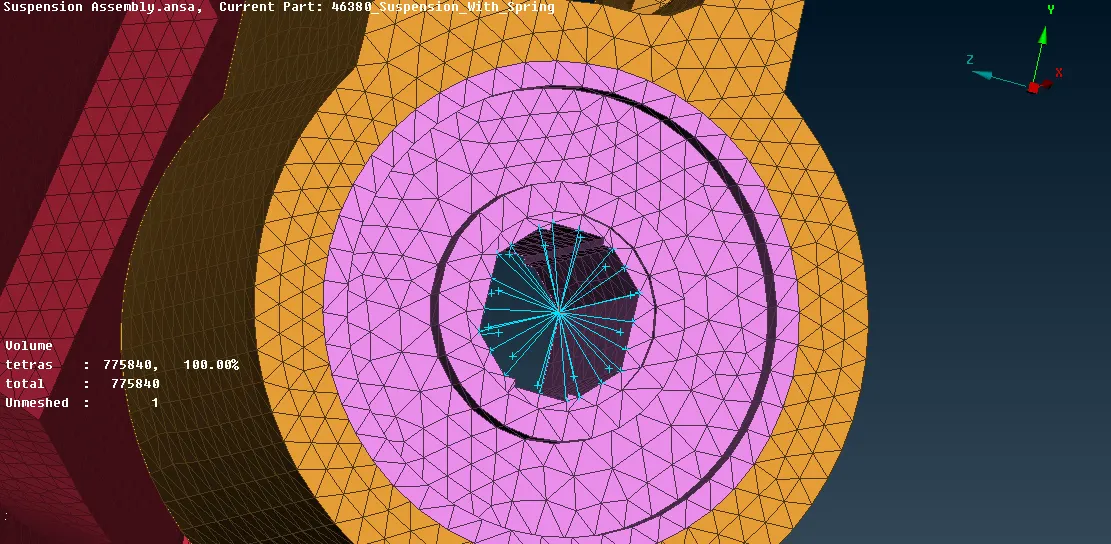
fig 8.1 RBE 2 Many Nodes Connections
2)RBE 2 Two Nodes Connections:
This is usually used to Connect the 2 node.For exampale this two node RBE 2 is to represent the Stem of the Bolt.
- Go to Nestran Deck.
- Connect the overlapping areas through RBE2 Cluster Element by selecting the Perimeter Nodes(Nastran deck>Elements>RBE2>Two Nodes) Yellow colour line represent 2 nodes RBE2 as shown in fig 8.2
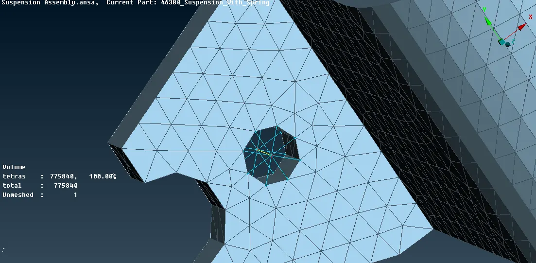
fig 8.2 RBE 2 Two Nodes Connections
9)1D Elements
While working with 1D elements,There are 3 types 1)CROD 2)CBEAM 3)CBAR
- In brief, CROD elements support tension and compression only, whereas CBARS and CBEAMS allow bending as well.
- A CBAR element is a kind of simplified CBEAM element and should be used whenever the cross-section of the structure and its properties is constant and symmetrical.
- The CBAR element requires that its shear center and the neutral axis coincide. Due to thisrequirement CBAR elements are not useful for modeling structures that may warp, such as open channel-sections. This limitation is not present in CBEAM elements.
Now lets See how to represent a Spring using CBAR in Nastran Deck
- Find the Spring in the model as shown in fig 9.1
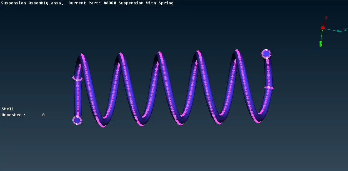
fig 9.1 Spring
- Take the Curve at the Middle of the Spring using Curve Middle(Topo Mode>Curves>Middle) as shown in fig 9.2
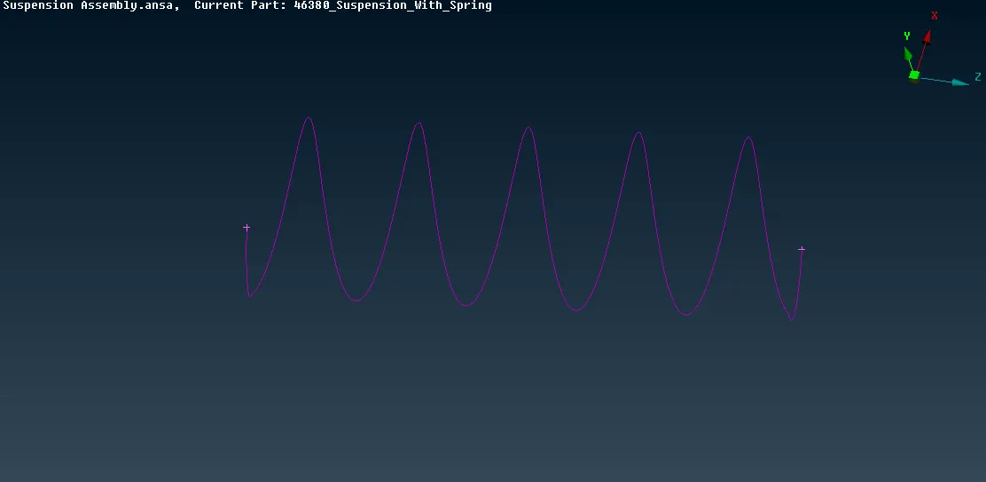
fig 9.2
- Now Go to Nastran Deck from Topo Mode.
- Go to CBAR(Nastran Deck >CBAR) and Select the Curve as shown in fig 9.3
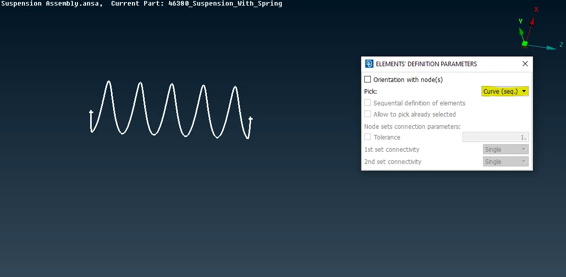
Fig 9.3 Selection of Curve for CBAR
- On Confirmation,Enter the "~ Element length" in the box popup on screen.
- On Pressing Enter,the CBAR Representation of Spring will be generated as shown in Fig 9.4
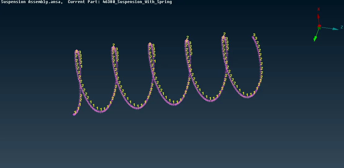
Fig 9.4 C BAR representation of Spring
- Now Give the RBE2 Connection to the CBAR and its Mating Component as shown in Fig 9.5
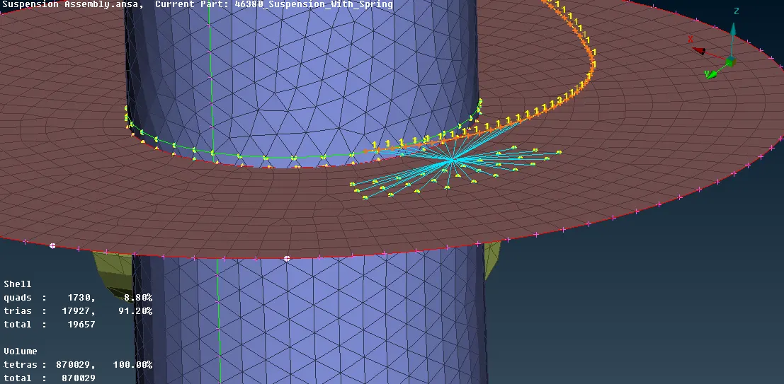
Fig 9.5 RBE2 Connection to the CBAR
- On Enabling the Material Orientation and Line Elements Cross section as solids in Presentation Parameters(Utilities>Quality Criteria>Presentation Parameters),we can See the Solid CBAR Spring as shown in Fig 9.6
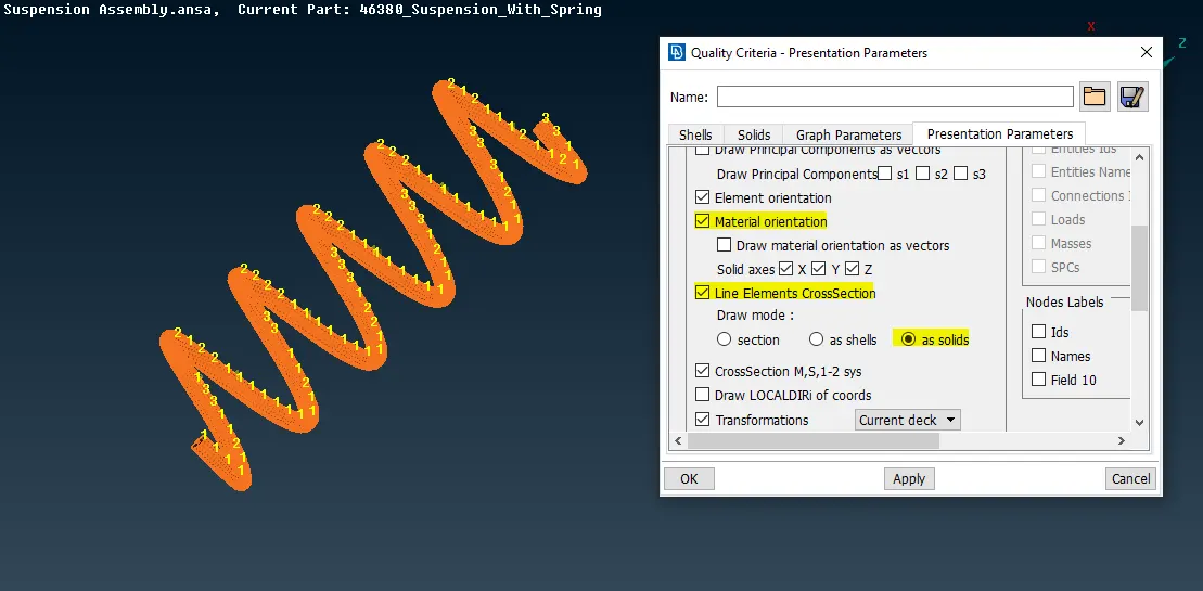
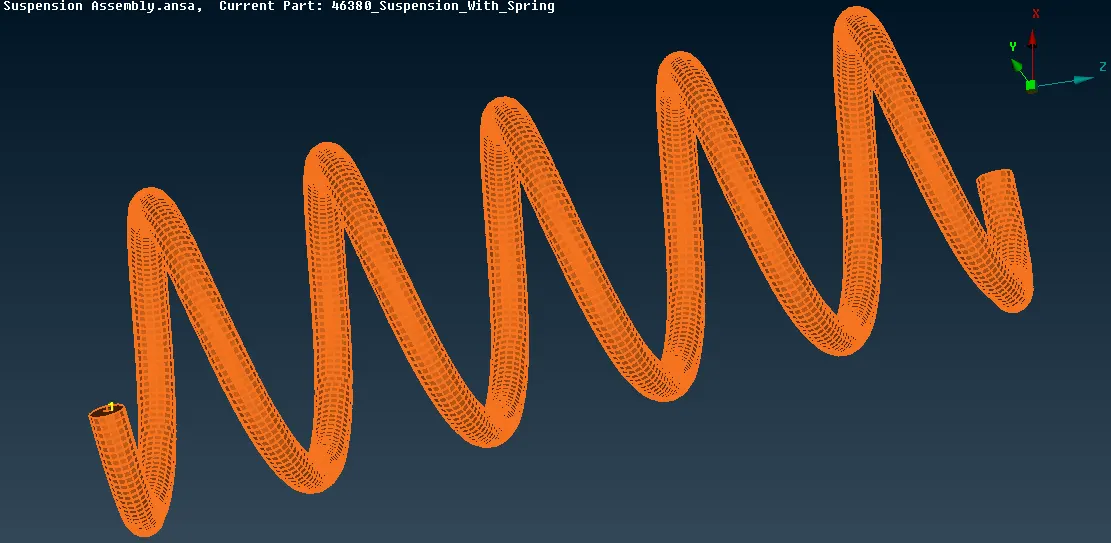
Fig 9.6 Solid CBAR Spring
Thus all the Connections Done in the Suspension Assembly.

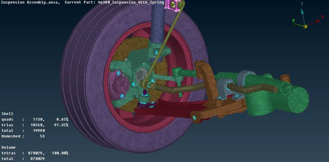
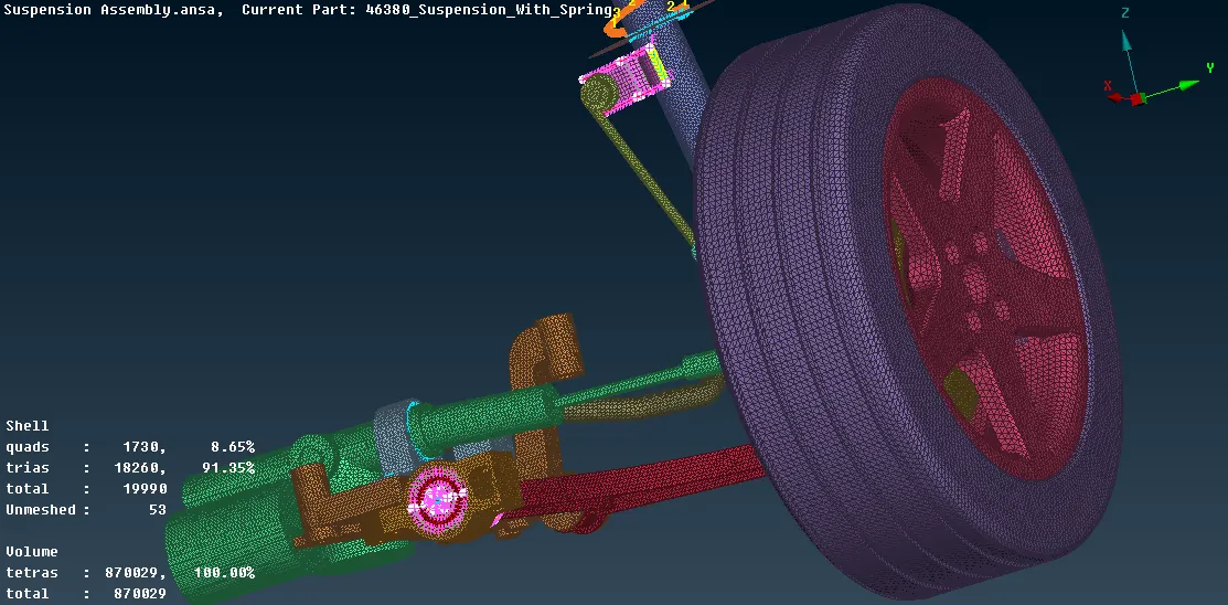
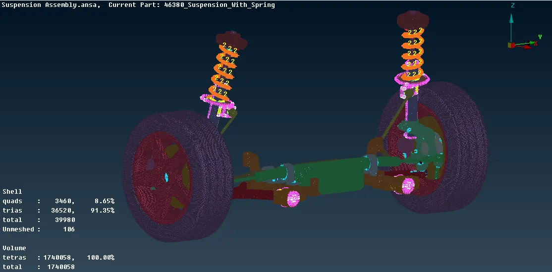
10)Enabling Symmetry of the Suspension Assembly
- After the connection we need to provide symtery to the model to get the complte Model.
- Go to Utilities>Transform>Copy.
- Select the Model and Press Middle Button
- Select Mirror 3 points Plane and Select 3 points on the Model as shown in the Fig 10.1
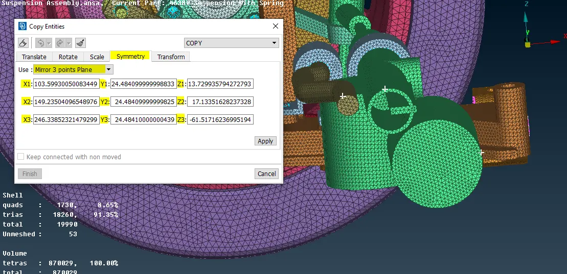
Fig 10.1 Selecting 3 Points
1)Able to fix Hepmetrical Errors and Geometric Cleanup of the Component.
2)Able to Creating and extracting of Mid Surface from the Parent Geomtery of the plastic Component.
3)Defeaturing of the Component
4)Meshing of the Component considering all given quality Criteria.
5)Understanding the Mechanism of the Suspension Assembly
6)Different types of Connection Techniques.
7)understandnteh imporatance of Spring in the Suspension Assembly
8)Representation of Bolt and Nut Connection.
9)Degrees of Freedom and its importance in NVH Analysis
Conclusion:
Thus the Meshing of the suspension has been done and connection is given wherever required to make the model Rigid and can be Concluded that for any Analysis ,understanding of Mechanism is very Much important before starting the Connection.All the Connection procedure is same for all the models but the requirement might differ from models to models depending upon the analysis.All the possible Connections are done for this models and the model is ready to give for the next Process.
Google Drive Link for the Model:
https://drive.google.com/file/d/1RL0gEKGMOmcQBtJVYn8GAOfxAV38F1hQ/view?usp=sharing