Project 2: Rear Suspension Model
Aim:
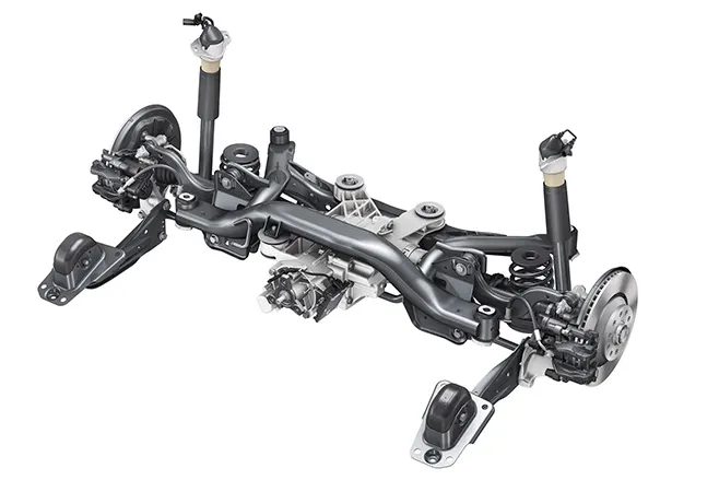
The main aim is to create a Volume Mesh and Give connections to the given Rear Suspension model according to the given Quality Criteria.

Methodology:
The process which is followed to get a proper volumetric mesh and connections done are as follows.
- Opening the File
- Checking the Geometry
- Generating the Mid surface
- Giving the Mesh
- Creating the Volume Mesh
- Giving the Connections to the Model
- Assessing the Model
Introduction:
Rear Suspension:
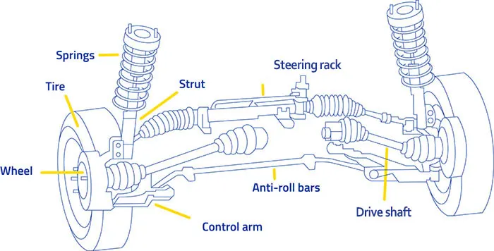
Suspension is the system of tires, tire air, springs, shock absorbers, and linkages that connects a vehicle to its wheels and allows relative motion between the two. Suspension systems must support both road holding/handling and ride quality which is at odds with each other. The tuning of suspensions involves finding the right compromise. The suspension needs to keep the road wheel in contact with the road surface as much as possible because all the road or ground forces acting on the vehicle do so through the contact patches of the tires. The suspension also protects the vehicle itself and any cargo or luggage from damage and wear. The design of the front and rear suspension of a car may be different.
The suspension of a vehicle directly affects characteristics such as passenger comfort and handling. The rear suspension of a luxury coupe is designed to maximize comfort and will have a softer suspension that absorbs more movement. A rear-drive sports car will require a stiffer suspension that allows power to be transferred from the driveshaft to the rear wheels more efficiently.
Functions of a Suspension system:
- To prevent the road shocks from being transmitted to the vehicle frame.
- To preserve the stability of the vehicle in pitching or rolling, while in motion.
- To safeguard the occupants from road shocks.
- To maintain proper steering geometry.
- To provide good road holding while driving, cornering, and braking.
Procedure:
- Opening the File:
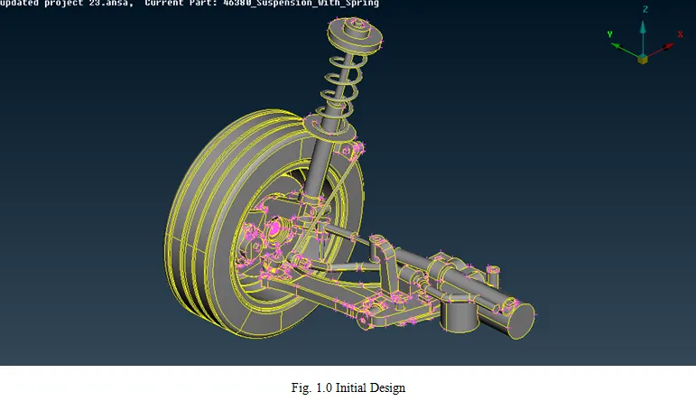
The file is downloaded initially. To open the file, follow the steps.
- Open ANSA >> Give Command Arguments >> OK >> Click Ctrl +O (for opening the file) >> Select the File>> Click Ok.
- On the Whole to describe the Opening of the file, click on the ANSA app, and wait for the launcher dialog box to appear.
- Once it appears, the dialog box contains the information called Additional ANSA command arguments are seen there will be an input box just below it.
- The argument has to be changed to “-performance_mode 3” (This means the performance of the app and it has Slower drawing and yet better quality.) then click ok to continue.
- The ANSA is now opened and then you can either open the file by using file option and open or Ctrl + O
- Checking the Geometry:
- This process is just used to check the topology of the model.
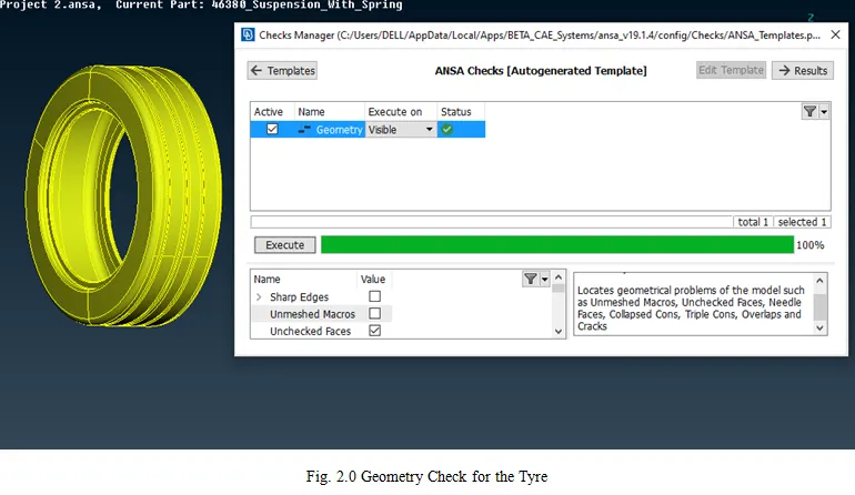
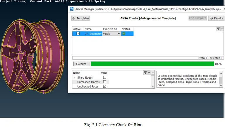
- In order to check the Topology follow the process as Tools>> Checks >> Geometry>> Execute.
- Once executed, it might show a green bar stating there are no errors in the geometry or it may show the dialog box showing the errors present in it.
- These errors can be fixed either by going on with them individually or once Right-clicked on the mouse an additional list pops- up.
- Fix option will be present in that pop-up when it is clicked the errors which can be fixed are executed and it might contain only a few errors which should be fixed manually and if no errors are present then it will show the green bar stating executed.
- The process is called geometric clean- up. It can be done either completely or part-wise of the parent geometry.
- Giving the PID:
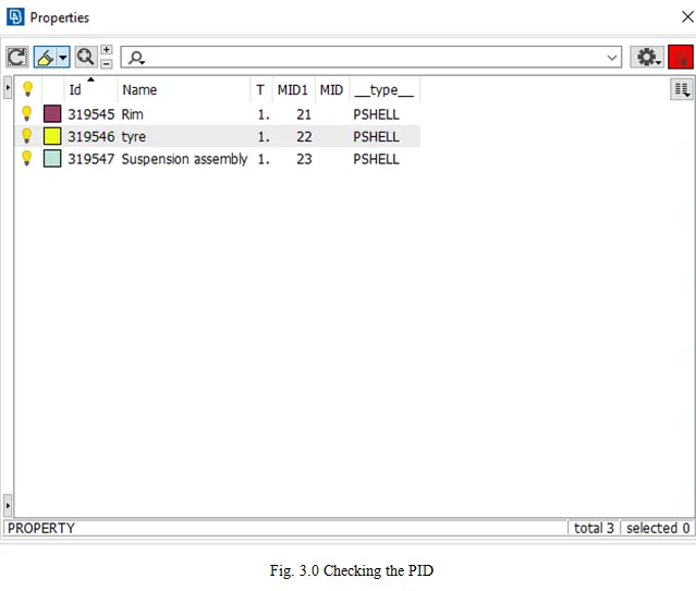
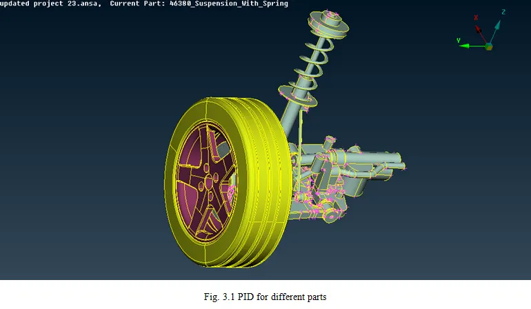
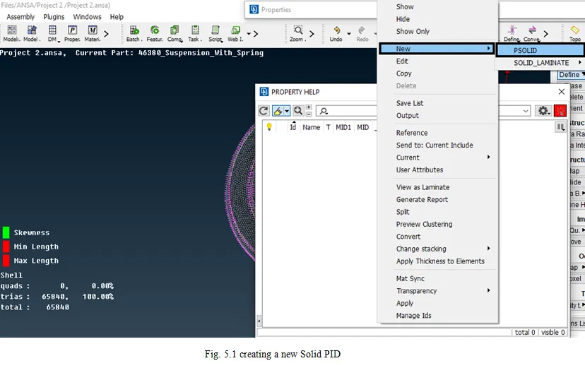
- The PID is used to create a property of the particular model parts or the total model. To create a new PID or to check the existing PID’s.
- Click Lists >> Properties.
- You can see the Properties which are created before.
- To create a new PID, right-click on the dialog box, the drop-down appears. Click New >> PSHELL>> PSHELL.
- Then a New PID is created.
- To assign a part to the PID. Select the element needed to be assigned and do the middle click on the mouse to confirm.
- Generating the Mesh:
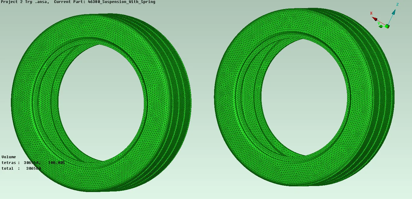
- For Tyre:
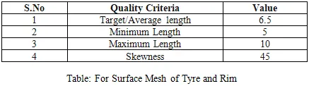
- The Tyre structure is hollow inside and doesn’t have thickness, therefore, the Mesh has to be done on the surface and the volume is needed to be generated.
- The volume which is generated is needed to be tetra element volume and therefore, the mesh should be Tria element.
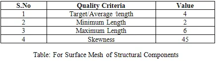
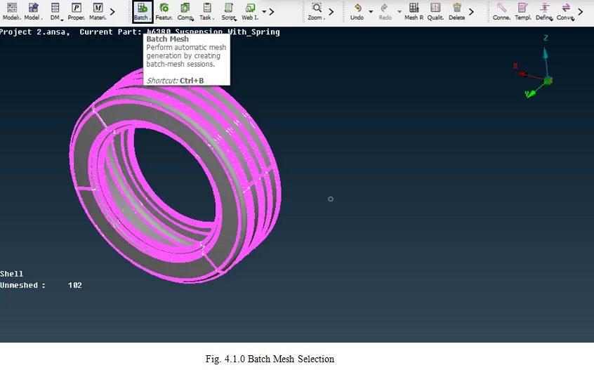
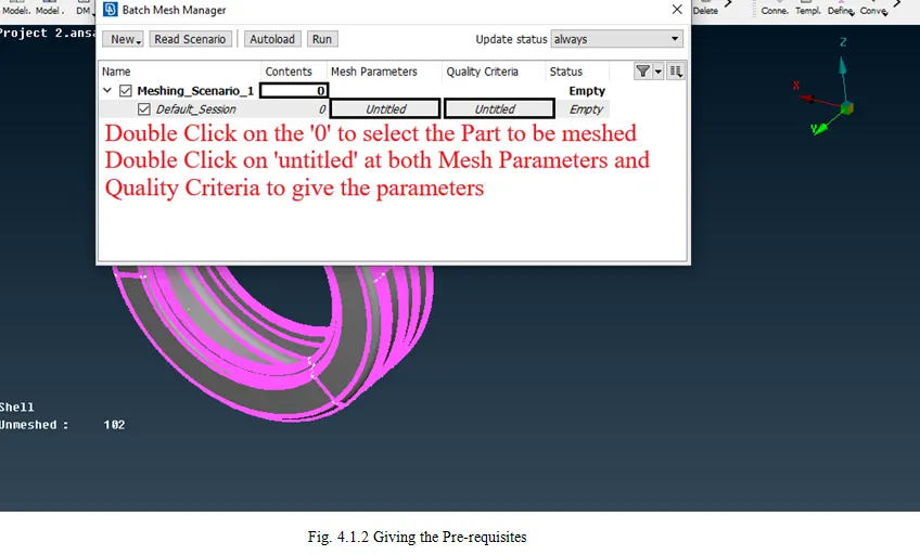
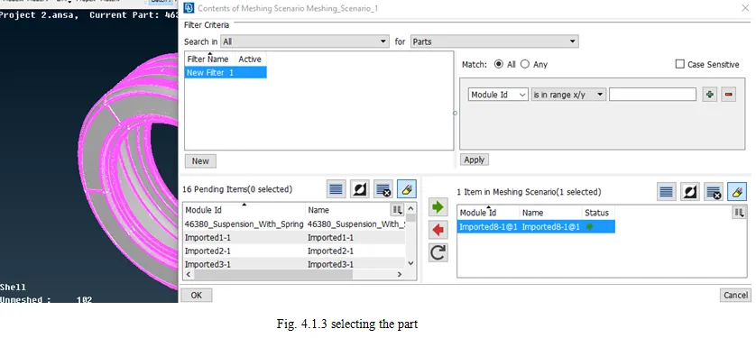
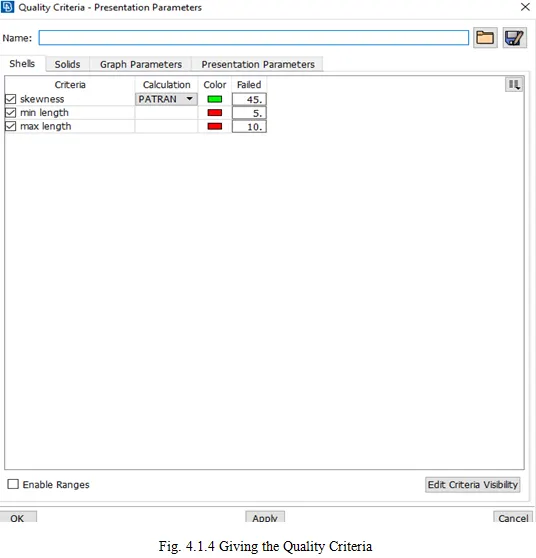
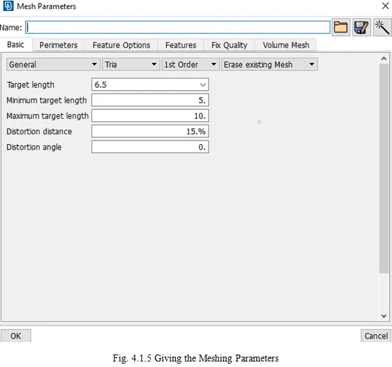
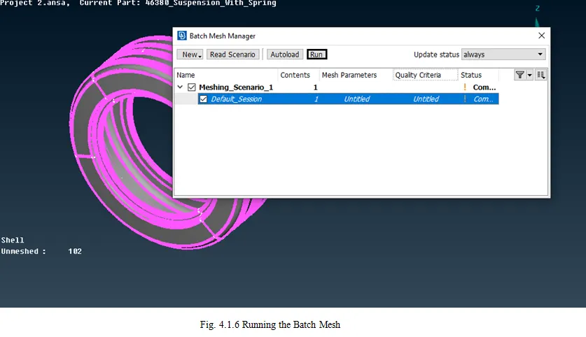
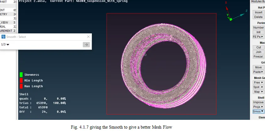
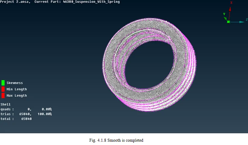
- For the Surface Mesh, manual mesh can be done but it takes much time. To reduce the time and to generate the mesh clearly, Batch Mesh is used.
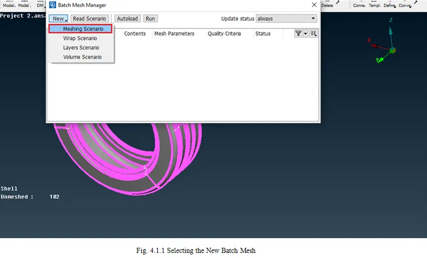
- For Batch Mesh, Click Ctrl +B >> New >> Meshing Scenario >> Select the Part >> Give the Quality Criteria and Meshing Parameters >> Run >> Mesh is Completed.
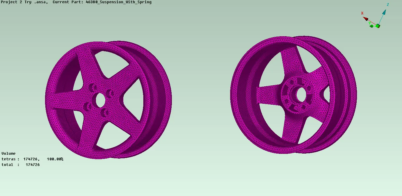
- For Rim:
- The Rim part is similar to that of the Tyre and therefore, a similar procedure is to be done.
- For the Surface Mesh, Batch mesh is done, the procedure followed is similar to that of the Tyre Part.
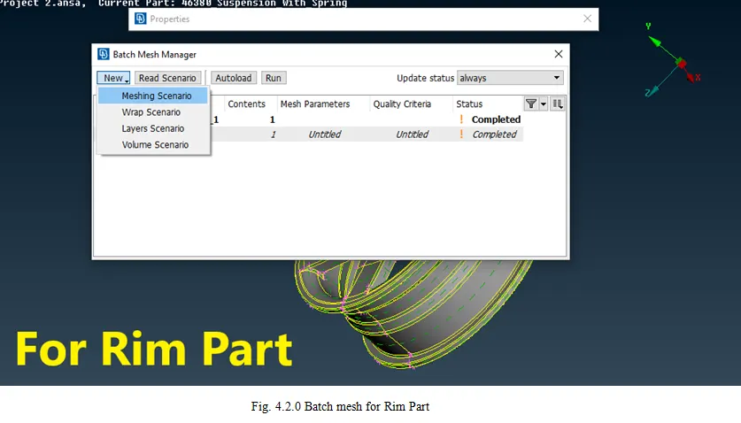
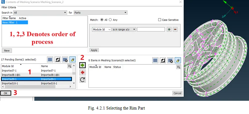
- The procedure is similar to that of the Tyre part and therefore the images are not repeated.
- For Structural Assembly:
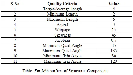
- The Structural assembly, however, does consist of different parts and therefore, different methods of mesh are done.
- For the Similar or Uniform thickness, Mid Surface is generated, and for hollow particles, Surface Mesh is created and then the volume is generated.
- In Topo Deck, Faces Tab>>select Mid-Surface >> Casting >> Give Minimum Thickness and Target element length >> Click OK.
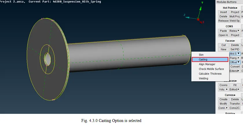
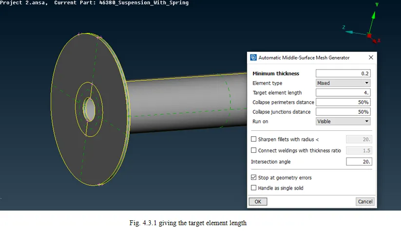
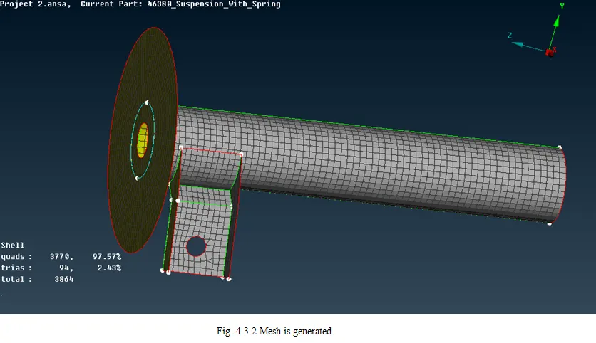
- The images are not added since the volume mesh is similar to the other parts mentioned above.
- Constructing the Volume Mesh:
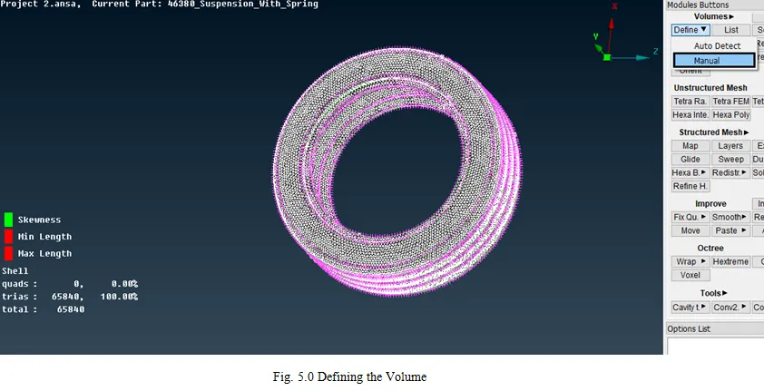
- For the Volume Mesh, the Part must be defined first to create a volume of that particular part.
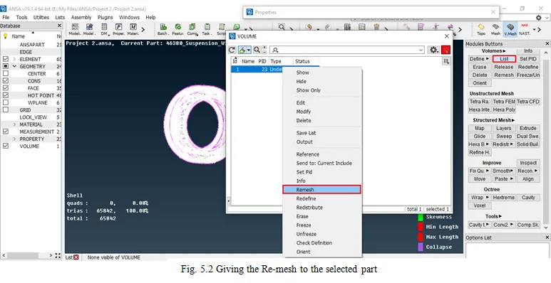
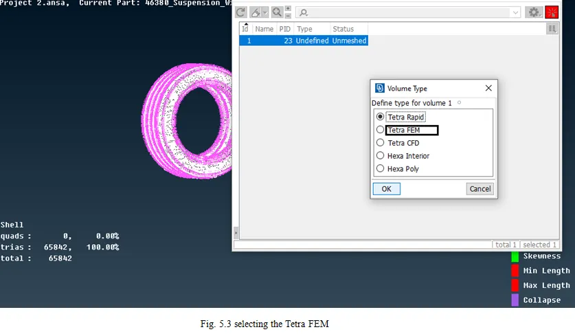
- Click Volumetric Mesh Deck >> Click Define >> Click Manual >> Select the Part >> Give the PID >> Click List >> Select the Unmeshed Part >> Select Remesh >> Select Tetra FEM >> Click OK.
- Checking the Volume Mesh:
- The Volume mesh is created and it might have some collapse regions on the volume which can be fixed by moving the meshed elements or by fixing it automatically by clicking the Fix.
- Connections:
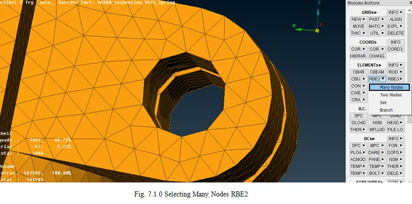
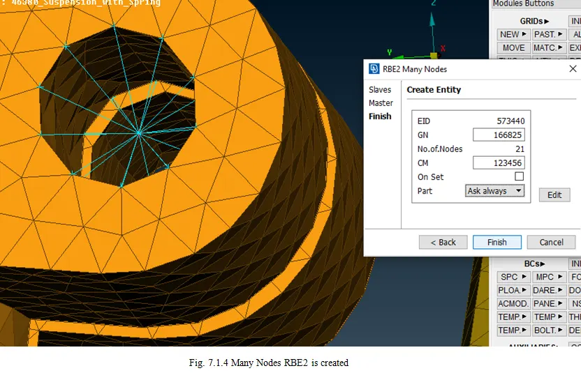
- Many Node RBE2:
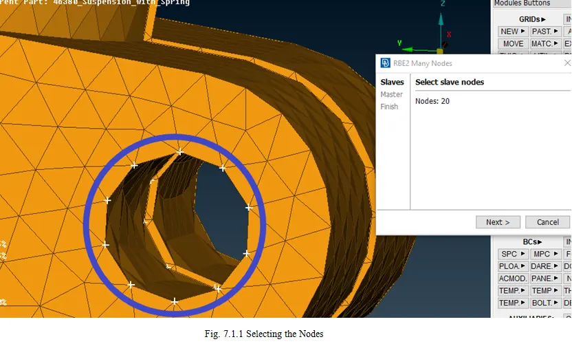
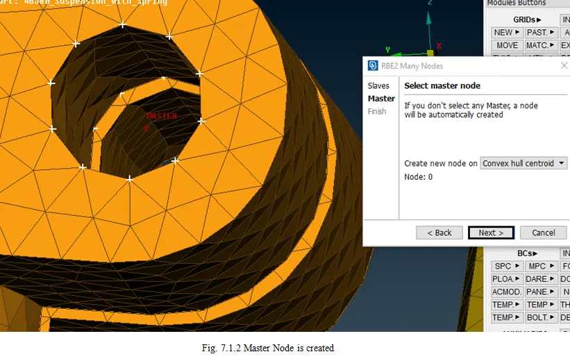
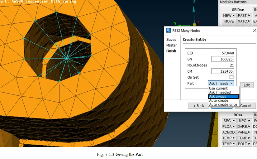
- The Many Node RBE2 is for the bolt regions, therefore the two end nodes are joined together. The steps are as follows:
- On NASTRAN Deck, Element Module >> Select RBE2 >> Many Nodes >> Select Slave Elements >> Master node can either be selected or it can be automatically generated >> On Create Entity >> Select the Always ask option >> Create a new part in the Model Browser
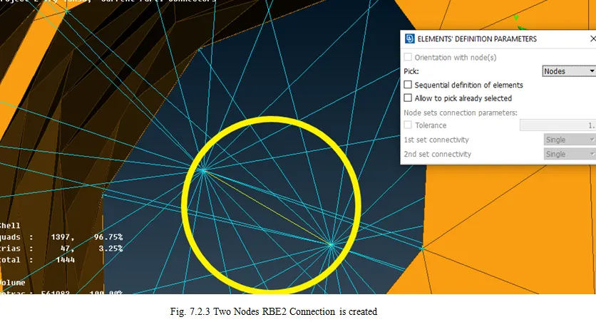
- Single Node RBE2:
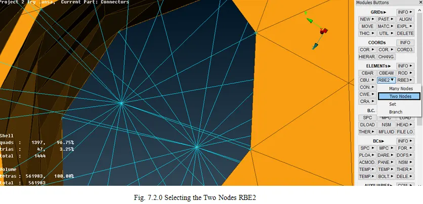
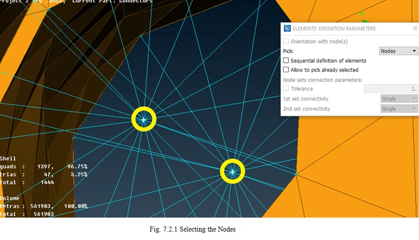
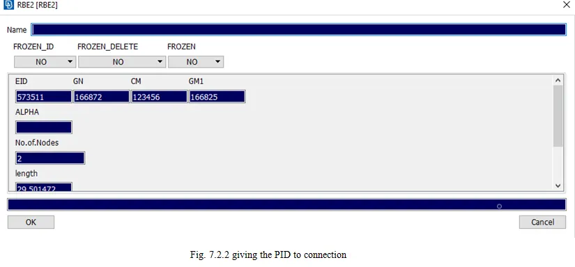
- The Single Node RBE2 is to give the connection to the parts that can be given to the nodes.
- On Element Module >> Select RBE2 >> Single Node >> Select two nodes to be connected.
- Seam Weld:
- To create the connection, the length of the connection is to be specified. To take the length of the connection to create the curve,
- In Topo Deck, Curves Module >> Select Cons2Curves >> Select the Con >> Middle-Click.
- The Curve data needs to be converted to the connection.
- Go to Assembly Manager >> Click Convert (Curves) >> Select the Curve >> Select the Connection Type >> Select the seam line >> the Seam Line is created.
- To realize the converted line and to establish a connection, the seam line needs to be created,
- Go to the Assembly Manager >> Click Connection Manager >> Select the line >> Connection Manager >> Select P1, P2 as the two-part in which the connection needs to be done >> Select FE Rep Type as Overlap Shell >> Give the Search Distance >> Give the Width >> In Shell Attribute, Create a new PID and Select the Property (Hint: Click on the tab and click “?” without the quotes).
8. Giving the Symmetry:
- The Symmetry is done to make the half of the Rear Suspension as the complete model. To complete the model follow the steps
- In Utilities Tab >> Select Transform >> Copy >> Select the Entities >> Select Symmetry tab >> Select Mirror 3 point Plane >> Select 3 points which create a plane to get a proper symmetry >> Click Ok >> Click Finish.
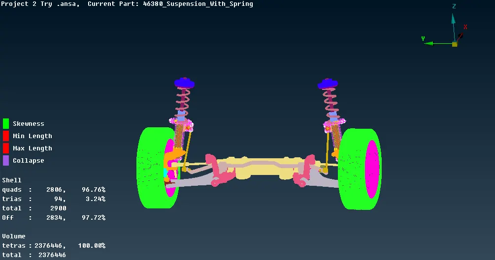
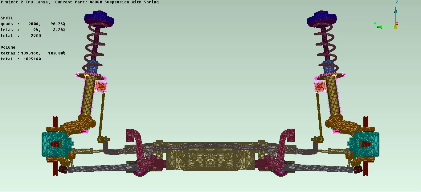
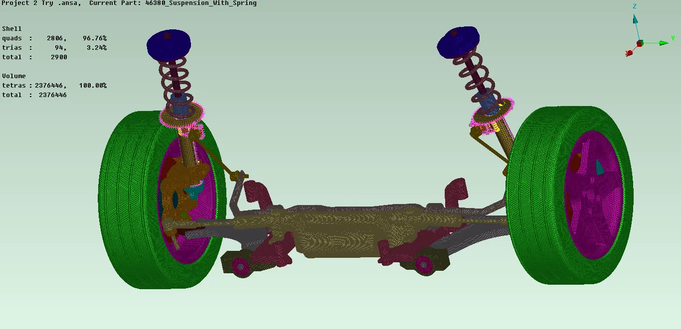
- The image above shows the model after the symmetry is done.
Errors:
The Errors are generally minimum and maximum length errors which are solved when the reconstruction is completed. There are many CAD errors in the design.
Results:
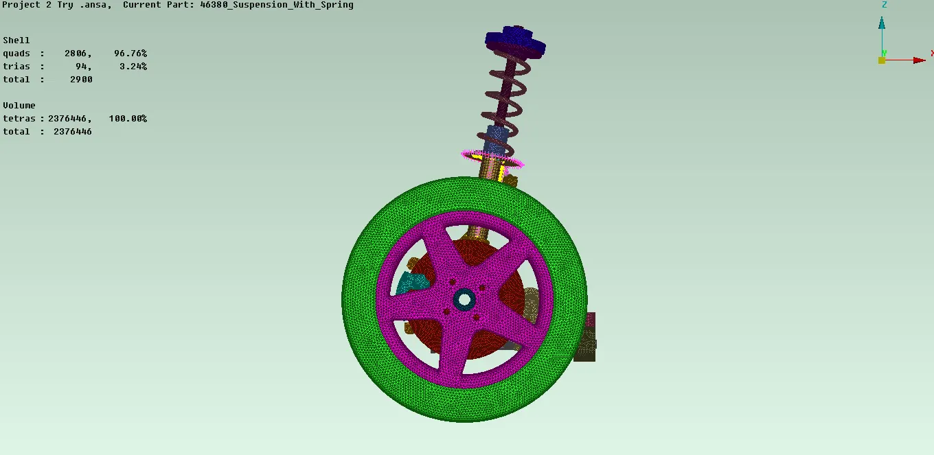
The CAD design which is given is completed with a good Mesh flow with the generated Volume and created connections.
- For Tyre Part:
- For Rim Part:
- For Structural Component:

Learning Outcomes:
The Model gave a chance to revise and reuse the topics learned in the previous modules and to advance the knowledge to get the good Finite Element.
Bibliography:
- Suspension systems: Rear Suspension
- Automobile Engineering by R.K.Rajput: Suspensions (Page No. 415)
Google Drive Link: Rear Suspension of a Car