Project 2 - Pre-Processing Of A Car Suspension Model
Pre-Processing Of A Car Suspension Model
Aim: To create the shell (2-D) and tetra meshing meshing for the Car Suspension Model by eliminating geometrical errors and considering the given element quality criteria, deploying the connections using ANSA.
Introduction:
The finite element method is a numerical technique for obtaining approximate solution to a wode variety engineering problems. FEA (Finite Element Analysis) has done by three phases.
1. Pre-processing
2. Solution
3. post-Processing
This project comes under Pre-processing. The goals of Pre-processing are to develop an appropriate finite element mesh, assign suitable material ID and boundary conditions. ANSA And Hyper-mesh are the example tools and in this project ANSA is used. ANSA interface is shown in the fig 0.1.
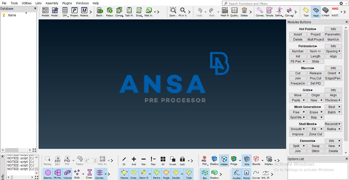
Fig.0.1: ANSA Interface.
Types of the elements
1. One-dimensional elements: This elements are suitable for one-dimensional problems such as bar, truss and beams.
Example- Linear element has 2 nodes etc.
2. Two-dimensional elements: This elements are suitable for Two-dimensional problems such as plane stress and plane strain in sheet metal parts up to thickness of 5mm.
Example- Tria Elements, Quad elements,
2. Three-dimensional elements: This elements are suitable for three-dimensional analysis. uses for solid parts and sheets of thickness more then 5mm.
Example- Tetra elements and hexa elements.
Above all types of elements are done under user defined Quality criteria. for example refer table1.1,1.2 &1.3
Element Quality Criteria for Mixed elements (For Midsurface only):
| S.No | Quality Criteria | Value |
| 1 | Target/Average length | 4 |
| 2 | Minimum Length | 2 |
| 3 | Maximum Length | 6 |
| 4 | Aspect | 3 |
| 5 | Warpage | 15 |
| 6 | Skewness | 45 |
| 7 | Jacobian | 0.7 |
| 8 | Minimum Quad Angle | 45 |
| 9 | Maximum Quad Angle | 135 |
| 10 | Minimum Tria Angle | 30 |
| 11 | Maximum Tria Angle | 120 |
| 12 | Tria Percentage | 15 |
Table1.1: Element Quality Criteria
Element Quality Criteria for Tria Elements (Tyre and Rim):
| S.No | Quality Criteria | Value |
| 1 | Target/Average length | 6.5 |
| 2 | Minimum Length | 5 |
| 3 | Maximum Length | 10 |
| 4 | Skewness | 45 |
| 5 | Tetcolapse | 0.2 |
Table1.2: Element Quality Criteria
Element Quality Criteria for Tria (For other components):
| S.No | Quality Criteria | Value |
| 1 | Target/Average length | 4 |
| 2 | Minimum Length | 2 |
| 3 | Maximum Length | 6 |
| 4 | Skewness | 45 |
| 5 | Tetcolapse | 0.2 |
Table1.3: Element Quality Criteria
Procedure:
The meshing is done by following steps
1. Import The Given file in to the ANSA
2. CAD Geometry clean up and topology
3. Mid-surface extraction
4. Setting the PID
5. Defeaturing
6. Meshing (Shell And Tetra)
7. Volume Define
8. Deploying Connections
1. Import ANSA in to the ANSA: Import the given Ip.IGS in to the ANSA Shown in the fig.1.1. Make orientation of all visual faces and change the element length on perimeter to 6.5 (for tyre and rim) 4 (for all other parts) (Target/Average length) in both perimeters and macros (MESH>Perimeters>Length). In work area on the screen we can see the Suspension model
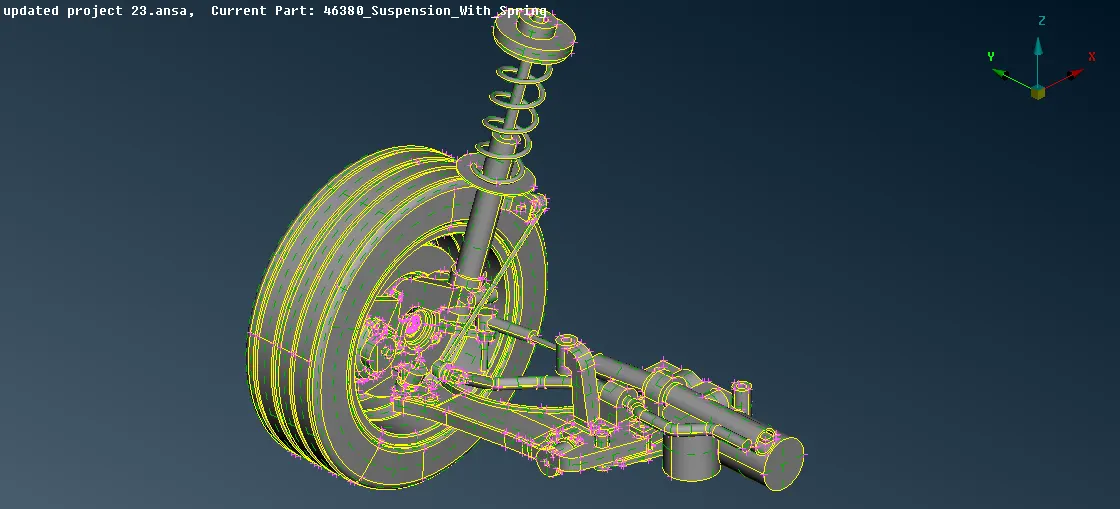
Fig.1.1: Imported File .ANSA
Here we can observe that most of the components are solid and few are sheets. so the messing process will be done as per the requirement
2. CAD Geometry clean up and topology: In this step the given model undergo geometry check (Tools>Checks>Geometry).
A. Activate the Check Geometry function.
B. The Checks Manager window pops up. The selected Check is loaded to an Auto generated Template.
C. Select on which entities the check should be executed "Visible", "Model" or "All Entities".
D. Activate the respective options in order to perform the check. select Unchecked Faces, Needle Faces, Collapsed Cons, Triple Cons, Overlaps and Cracks
E. Press Execute to run the check shown in the fig 2.1.
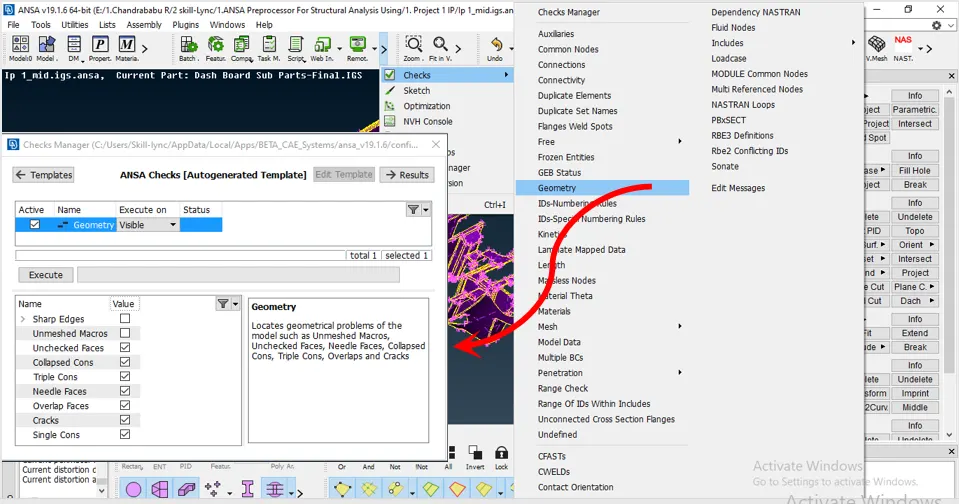
Fig.2.1: Geometry Check Manager
F. Where ANSA check for any geometrical errors such as collapsed faces, cracks, single con, triple con etc. those errors are shown in fig. 2.2.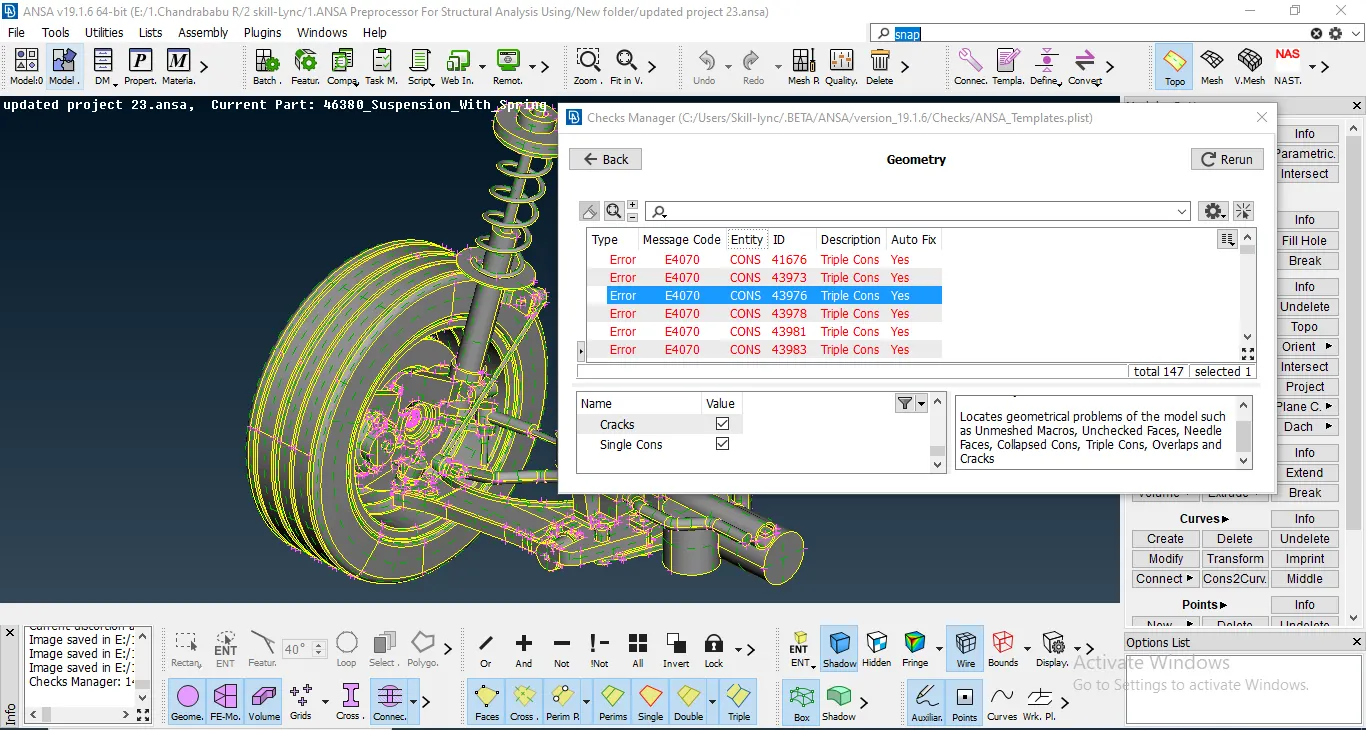
Fig.2.1: Geometry Errors
Its very difficult for clear geometrical errors for entire assembly so that in order to clear taking each part individual parts. Geometrical errors are cleared by using release triple cons and topo, deleting the overlapped faces and creating new faces. Here some geometrical errors auto fixed, some are done by deleting faces and re creating faces by NEW (TOPO>Faces>New>COONS)Fig.2.2 shows the fixed all Geometrical errors
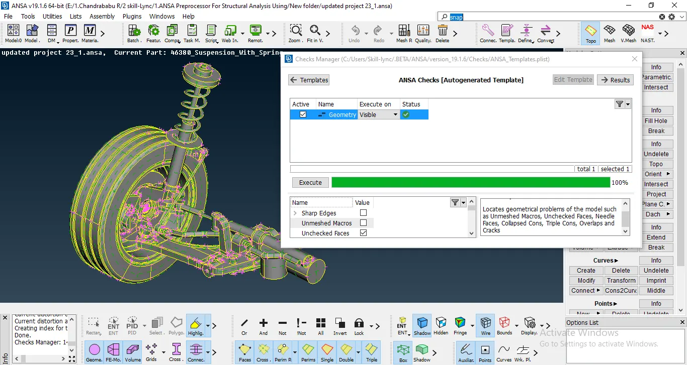
Fig.2.2: Geometry Clean Up
3. Mid-surface extraction: The given model is plastic component and before going to the Mid surface extraction check for uniform thickness entities and measure (Utilities>Measure). found uniform thickness for outer face and ribs are varying thickness.
Mid-surface extraction done by manually. Because all sheets are very simple we can take mid-Surface easily.
1. Activate the Offset Faces function.(TOPO>Faces>Offset>Faces)
2. Select the faces of same thickness value using the right mouse-button
3. Press the middle mouse-button to confirm selections. An arrow appears showing the offset-direction.While extracting the mid-surface by Offset method it will ask for the offset distance along with direction. With respect to direction input the value. The value may be +ve or -ve depending on direction. Input an offset value as -0.3mm because here thickness of selected faces is 0.6mm shown in the fig 3.1.
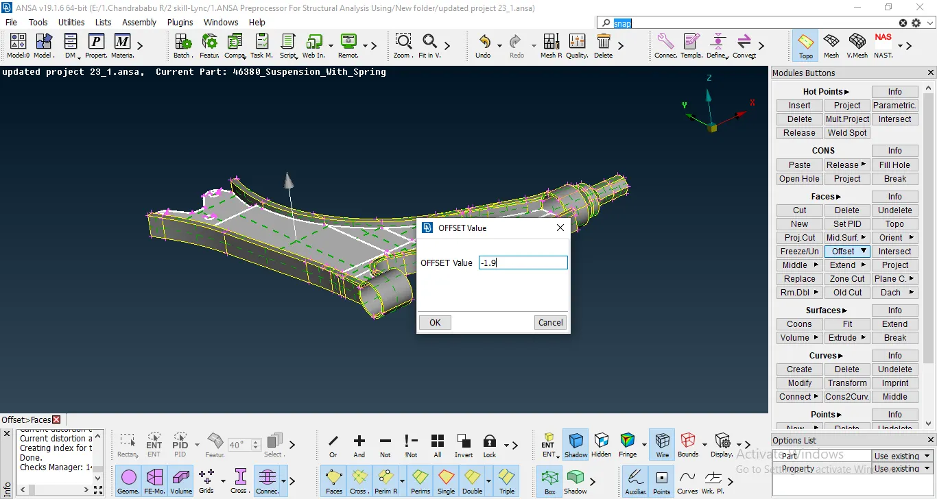
Fig.3.1: Offset
4. Decide whether to delete or not the original faces by pressing the relative button in the Confirmation window. The new Faces are defined.
Similarly Mid-surface extracted for different features on given model.
Once extraction done for all features extend all rib to parent mid-surface by following steps
1. Activate the Extend (TOPO>Faces>Extend>Target)
2. Select the single cons from the face which is to be extend
3. Middle mouse button and select the target faces
4. Confirm selection by middle mouse button and the faces will extend shown in the fig 3.4
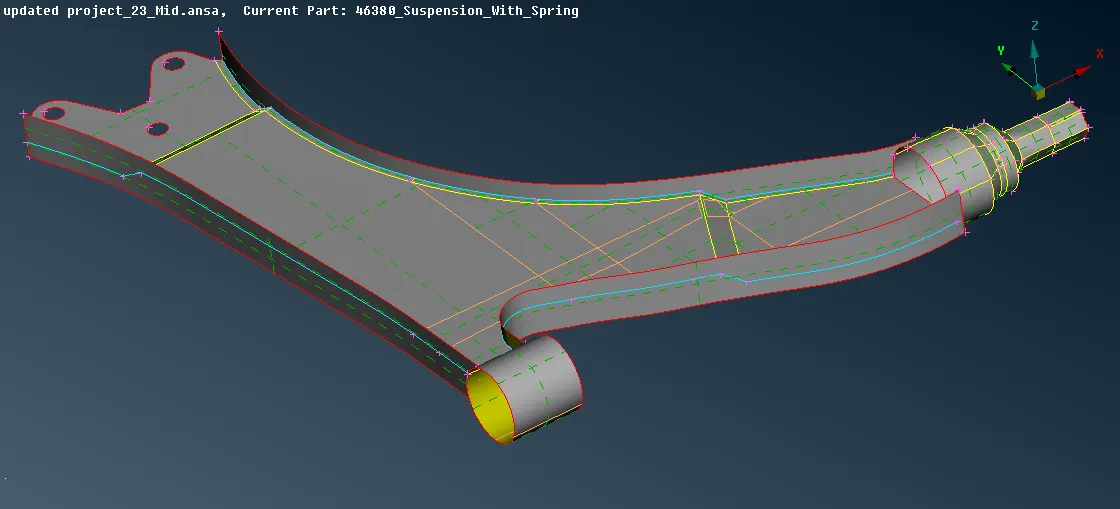
Fig.3.4: Mid-surface
4. Setting the PID: setting PID (Property ID) for each mid surface done by using Set PID (Topo>Faces>Set PID) This function assigns selected Faces, Shells or Groups of entities to an existing or new PID. The following steps for setting PID
1. Activate the Set PID ANSA asked to select faces
2. Conforming the faces, A Property Help window will pop up, in that window create new PID by right clicking mouse button and select New>PSHELL.
3. Another PSHELL window will popup there we can assign the Name, MID (material ID) and thickness. We can modify the colors of each PID. (But in this case we have different thickness at different region so we need to set PID according to the thickness after mesh and for initially we are going to set PID for reference purpose)
4. Press OK and Double click on current PID. New PID created shown in the fig.4.1
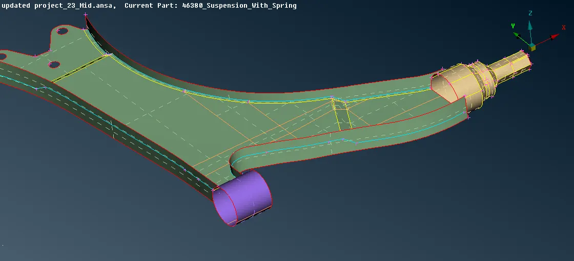
Fig.4.1: PID For Sheets.
Similarly separate the solids parts shown in the fig 4.2
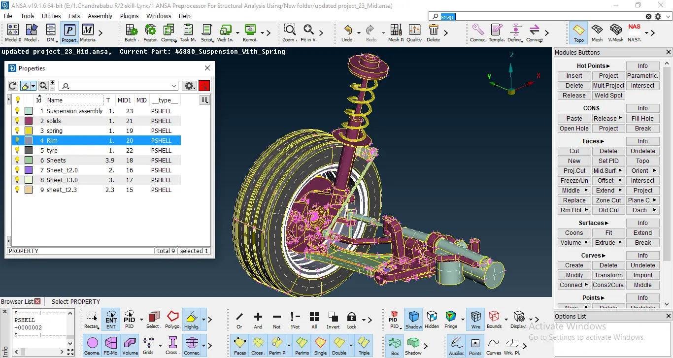
Fig.4.1: PID For solids
5) Defeaturing: Update the element length as per given element Quality Criteria (Mesh>Perimeters>Length) which is Target/Average length 6.5 (for tyre and rim) 4 (for all other parts) Removing all unnecessary edges, fillet radius etc. also maintain distance between two cons or nodes not less than Minimum Length of 2 (for all other parts) and 5(for tyre and rim).
6. Meshing: For the given component we can observe Both Shell and tetra mesh has to done. The following two types of mesh is going to perform.
A. Shell Mesh: Assign given element Quality criteria in to the ANSA (Utilities>Quality criteria) and Mesh Parameters (Utilities>Mesh Parameters) for sheet metals shown in Fig.6.1A. Here we are going to Generate Shell Mesh which is preferred for 2D mesh.
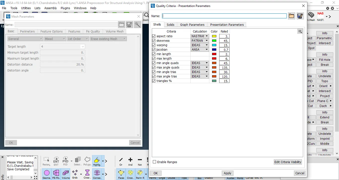
Fig.6.1A: Quality Criteria & Mesh Parameters.
Start meshing Process by Best Mesh (MESH>Mesh Generation>Best).
1. Activate the Best Mesh MESH>Mesh Generation>Best>Select and select faces.
2. Confirm the selected faces by middle mouse button.
3. The mesh will generate shown in the fig 6.2A
4. Modify mesh flow using Reconstruct (MESH>Shell Mesh>Reconstruct), Smooth (MESH>Shell Mesh>Smooth) and Split (MESH>Elements>Split). Make sure that while doing mesh all the element Quality criteria mush satisfied. Avid maximum opposite trais and quad elements.
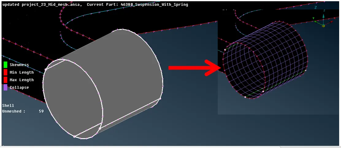
Fig.6.2A: Best Mesh
Over all mesh flow for sheet parts also show in the fig6.3A we can see the data of quads, trias, off elements and total elements.
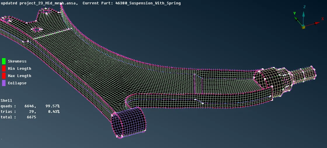
Fig.6.3A: Mesh flow
Thickness assigned to the parts by selecting Draw Shell As Solid (Utilities>Quality criteria>Presentation Parameters). each and sheet and ribs mush measure and set PID for each varying thickness Feature. shown in the fig.6.5.
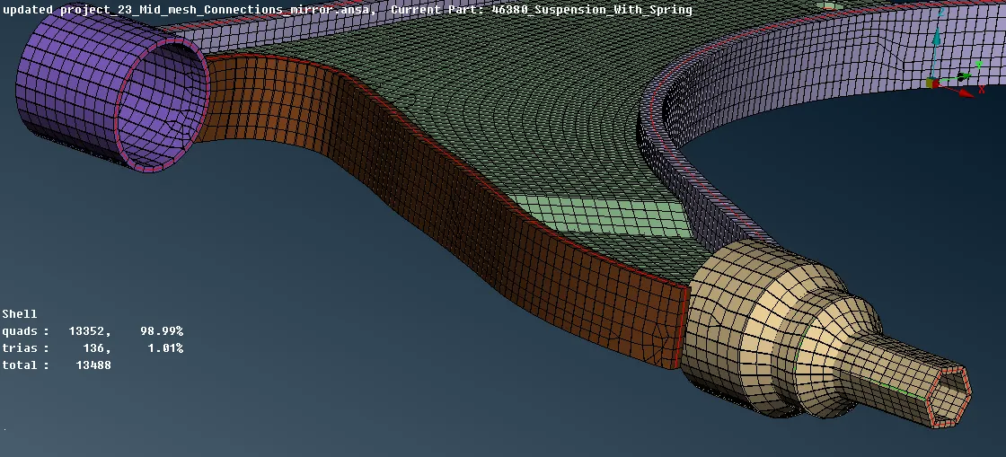
Fig.6.5: Thickness Assigned
Assigning separate PIDs for different thickness region. If we have varying thickness (taper).Then divide that region with respect mesh flow and assign thickness value from maximum to minimum with equal intervals.
B. Ortho tria or tria meshing: Assign given element Quality criteria in to the ANSA (Utilities>Quality criteria) and Mesh Parameters (Utilities>Mesh Parameters) in the given project we have two Quality criterias one is Tyre and rim, 2nd is for all other solids shown in Fig.6.1B
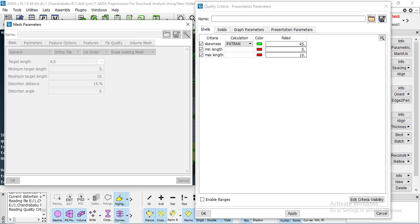
Fig.6.1B: Mesh Parameters for Tyre & Rim
Here we have selected ortho tria but while doing mesh we can change as per requirement in option list element type. Ortho tria is used where the geometrical features such as holes, curve areas computation time is more compared to normal tria etc. And tria is used at flat faces.
Start meshing Process by Spot Mesh (MESH>Mesh Generation>Spot Mesh>select). while generating we can change element type in option list shown in the fig6.2B
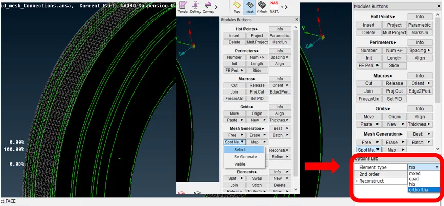
Fig.6.2B: Spot Mesh
Modify mesh flow using Reconstruct (MESH>Shell Mesh>Reconstruct), Smooth (MESH>Shell Mesh>Smooth). Make sure that while doing mesh all the element Quality criteria mush satisfied. In the fig 6.3B ,6.4B & 6.5B show the mesh flow of tyre, rim & other solids
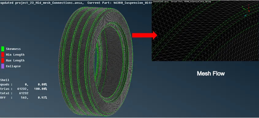
Fig.6.3B. Tetra Mesh for Tyre
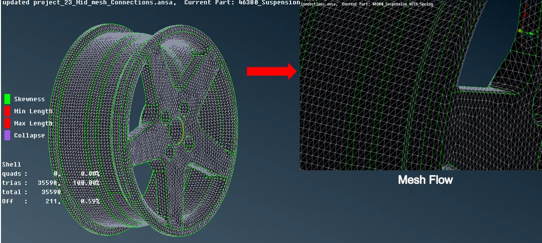
Fig.6.4B. Tetra Mesh for Rim
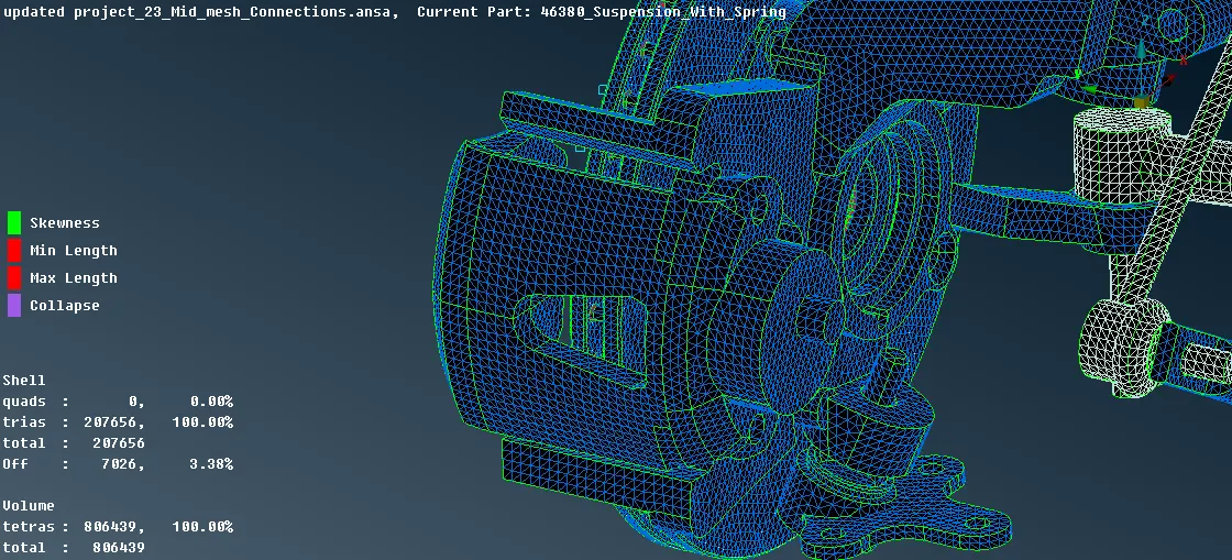
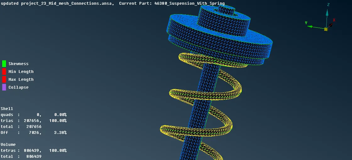
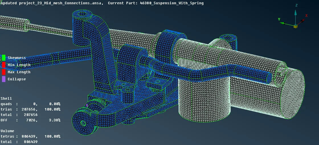
Fig.6.4B. Tetra Mesh for Other Solids
7. Volume Define: This function automatically defines multiple volumes using already meshed macros or FE-model mesh. Once mesh is done on surface we need to define the volumes for each individual separately. Define volume under (VOLUME MESH>Volumes>Define>manual) Steps to define
1. Activate the Detect function.
2. Select to detect volumes either from the whole database or from what is visible on the screen.
3. Select either to include solid facets of the surface in the detection.
Select each part separately and assign volume shown in the fig7.1. In the figure we can see that total volumes are 23 and unmeshed.
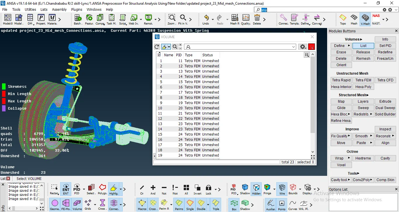
Fig.7.1: Volume Defined
7.1. tetra meshing for volume: Tetra meshing: It is also called Unstructured Mesh where the created volume filed by tetrahedral elements. Tetra rapid and tetra FEM are commonly used mesh types. In tetra rapid the Tetra Rapid algorithm meshes the Volume with Tetra Elements. In tetra FEM function automatically creates a tetrahedral mesh inside selected Volumes, initially with pyramid elements if the starting surface mesh contains quad elements. It is to be used mainly for structural applications.
Here we done with tetra FEM for better results (VOLUME MESH>Unstructured Mesh>Tetra FEM). Steps
1. Activate the VOLUME MESH>Unstructured Mesh>Tetra FEM function.
2. Select the Volumes or Solids to be meshed with Tetrahedral elements. Select one by one, using the left mouse-button.
3. Declare the end of selections, using the middle mouse-button.
4. Tetrahedral elements are generated inside the selected Volumes shown in the fig 7.1.1 And to conform the cut section shown in the fig7.1.2
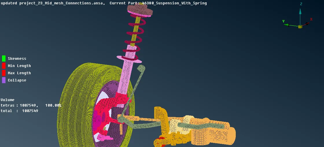
Fig.6.1: Tetra FEM
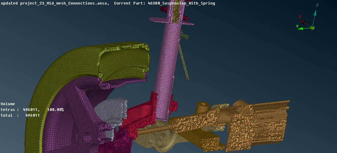
Fig.6.2: Section view
7.2. Check for tetcolapse: After solid mesh we need to check for tetcolapse by inputing the given tetcolapse valuve 0.2 in Quality criteria>solids.
8. Deploying Connections:
A. Before starting connection make sure that the model should be meshed and all type of the connections are mentioned. Check the type connections such as Bolt connections, spot weld, seam weld, damping connections and etc.
B. In ANSA every connection has degrees of freedom and numbered as 1,2,3,4,5&6. Every number associated with particular direction shown in the table 8.1
| Sl.No | Axis | Direction Of Movement |
| 1 | X-1 | Translational along +X,-X |
| 2 | Y-2 | Translational along +Y,-Y |
| 3 | Z-3 | Translational along +Z,-Z |
| 4 | X-4 | Rotation X |
| 5 | Y-5 | Rotation Y |
| 6 | Z-6 | Rotation Z |
Table 8.1
Create The Connections:
Following types of connections are made on rear door.
A. Bolt Connection:In bolt connection we are joining 2 or 3 parts together for making rigid connections using NASTRAN deck. In ANSA NASTRAN deck bolt connection can be achieved by three methods.
1.RBE2 (rigid body element of form 2) With stem (shank): Here connection is made for 2 or 3 holes by making separate RBE2 many nodes (NASTRAN>ELEMENTs>RBE2>Many Nodes) for all holes.And connecting all with the help of stem by RBE2 two nodes (NASTRAN>ELEMENTs>RBE2>Two Nodes) shown in the fig8.1

Fig.8.1: Bold Connection.
While Using RBE2 new window pop up for selection of nodes or elements click next and another window will pop up there we can see details such as element ID, Grid Point, degrees of freedom etc. The nodes which are on hole perimeter are called slave nodes and middle node is called masted node. 2 master nodes are joined by stem.
2.RBE2 (rigid body element of form 2) Without stem (shank): It is similar the first method but we are selecting all nodes from different holes together to make single master node. here stem of bolt is not available. shown in the fig.8.2
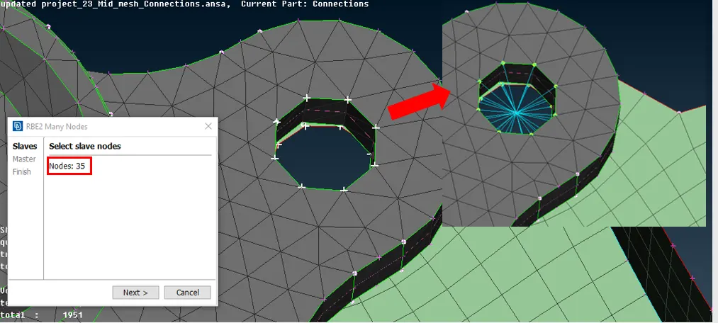
Fig.8.2: Bold Connection.
3.Automated Connection: In Automated first we have to create 3D point on hole by using TOPO>Points>On COG>Edges. convert 3D point to connection type as a Bolt in MENUBAR>Assembly>Convert while converting it will ask for type, select 3D points type and select point again it will ask for type of connection select as bolt and press OK . by using connection manager we can generate bolt connection shown in the fig.8.3
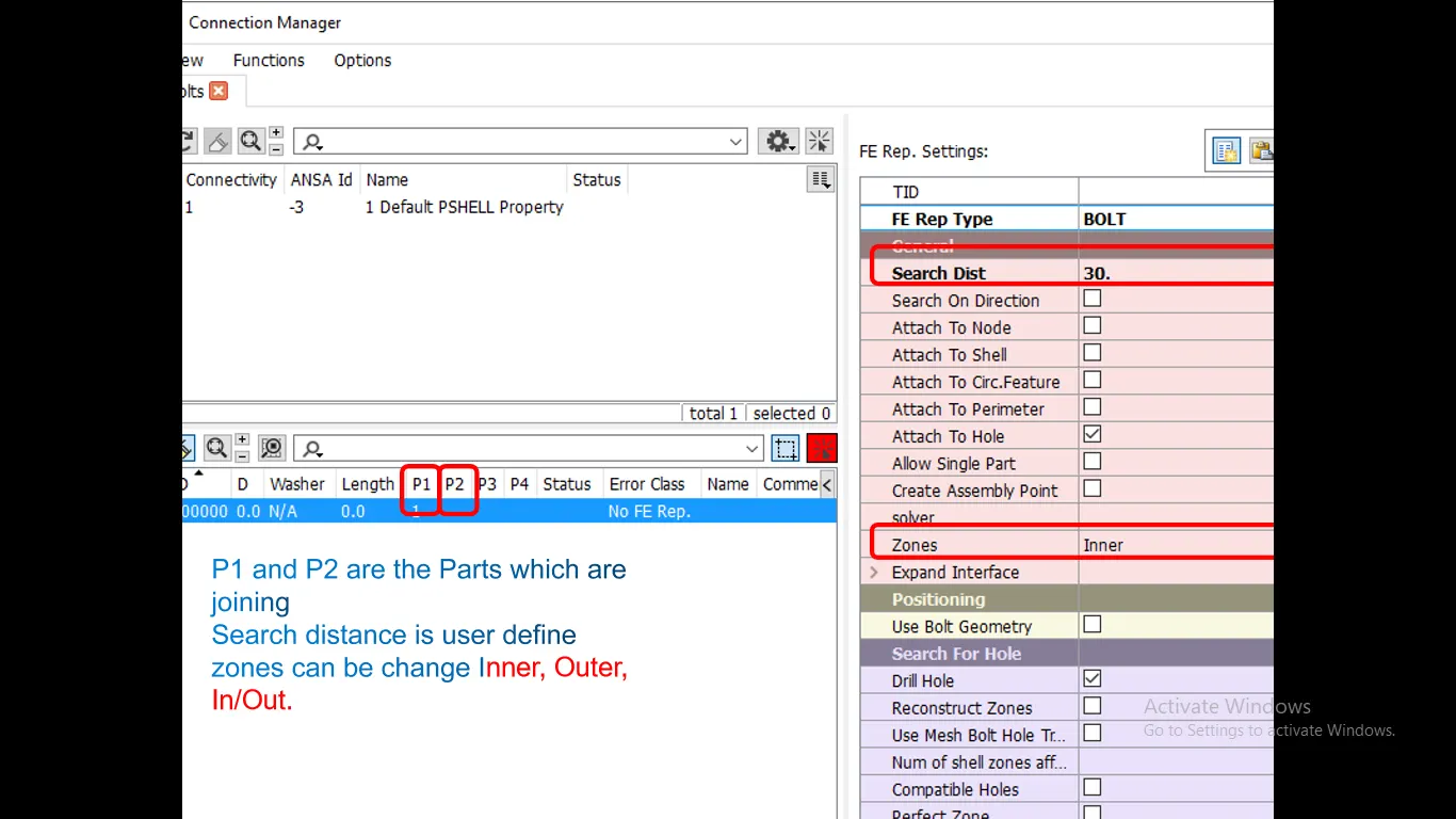
Fig8.3: Connection Manager
Seam Weld connection: In this first we have to Convert con to curve by using TOPO>Curves>Cons2Curves. convert curve connectiontype as a seam line in MENUBAR>Assembly>Convert while converting it will ask for type, select curves and select curve againit will ask for type of connection select as seam line and press ok . by using connection manager we can generate bolt connection shown in the fig8.4
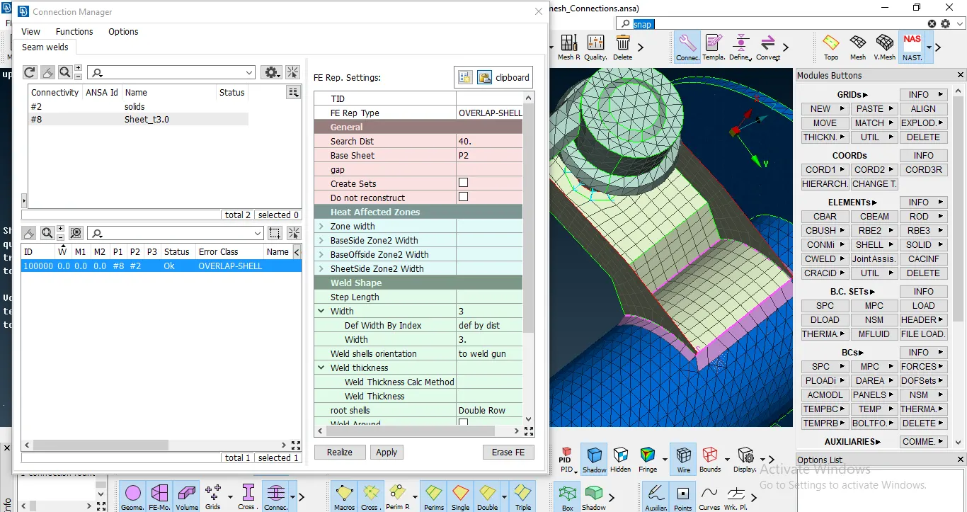
Fig.8.4: Seam Weld
Similarly connections are made. In degrees of freedom we can remove constraint by deselecting numbers from 123456 depending on the direction refer table 1.1.
The model has to be mirror to see the both side using Transform (MENUBAR>Utilities>Transform). This function is used to Translate, Rotate, Transform, Scale, Symmetry or Mirror selected entities (Faces, Points, Elements etc). The selected entities are copied in the new position. shown in the fig 8.5

Fig.8.5: Mirror Model
Learning Outcome:
Learnt user inter face of ANSA.
Learnt CAD geometry clean up, topology, Mid-surface extraction And Defeaturing for sheets and solids
Learnt shell meshing and making good mesh flow with considering the Quality criteria sheets and solids
Learnt how to give Thickness for non-uniform and varying width.
Learnt user inter face of ANSA for NASTRAN deck
Learnt making connections such as Bolt connections, spot weld, seam weld, damping connections and etc.
Conclusion
shell (2-D), tetra meshing meshing and deploying the connections for the Car Suspension Model is done successfully by eliminating geometrical errors and considering the given element quality criteria using ANSA.
(Find the attached file of updated project_23_Mid_mesh_Connections_mirror)