Project 2
Aim: To create Mold assembly with sliders, ejector system, air vents for the given component.
1. Core and Cavity Surface:
To create the surface, first the parting line is decided at the bottom of the component after scaling of the prdoduct is done. Next, using shut-off surface command the open profiles are first closed. Creating split line along the bottom face to extend the same, creating the cavity and core surface.
Once, all surfaces are ready, they are knited with Core and cavity surface created after the shut off surface seperatly. Thus, Core and cavity surface are created.
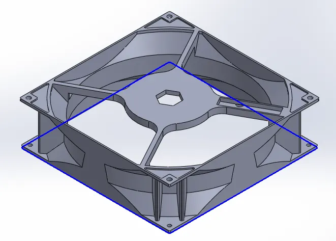
Parting Line (in blue)
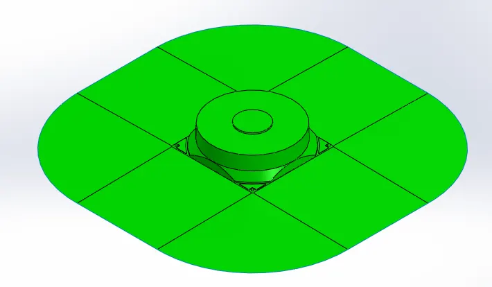
Cavity Surface
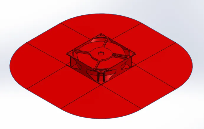
Core Surface
2. Core and Cavity Block:
Core and cavity blocks are made is different files. Hence, the core and cavity surface are added to the asembly as a seprate file. Next, a profile for the 2D surface is created with enough clearance between for 3D profile. Next, the skecth for 3D profile is drawn and split from the outter bigger block. The inner block is cut with the core surface and the outer block's face is moved upto the core surface. Next, the height of the block is checked and adjusted to 200mm.
For The cavity block, same procedure is followed. Since, the cavity and core block moves against eachother, relief is provided to avoid rubbing agaisnt each other.
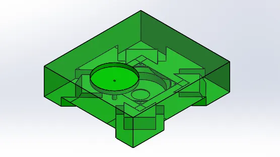
Cavity Block
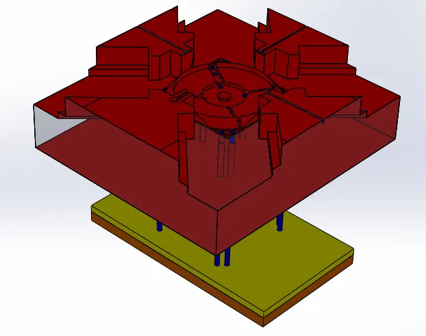
Core Block
3. Sliders:
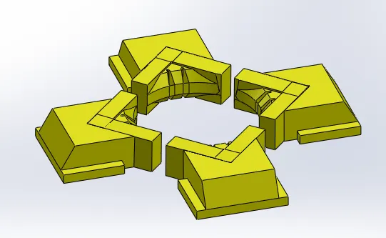
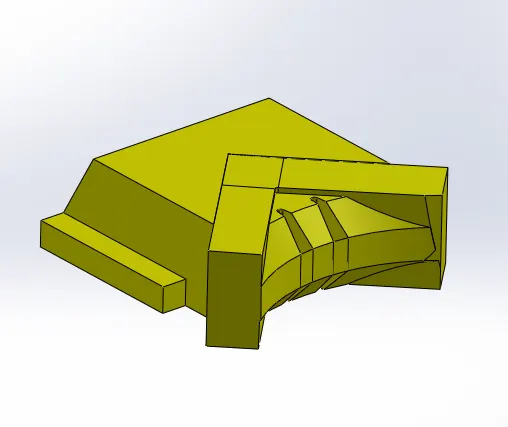
Since there is an under cut present in the core block, slider needs to be created. Hence, first the core block is split such that there is no under cuts or sensetive geometry created. Next, only the necassry part needed is split into slider, remaining part is converted into an insert as this part will wear out easily due to continous movement of the slider.
Next, the collar is added to the slider and path for the slider is cleared. Space is cleared in the core block for teh washers and nuts. Similarly, the necassary changes are done in the cavity block.
4. Ejector System:
To eject the plastic component out of the COre blcok, ejectors are required. As the ejectors are on a slope D type ejectors are needed. Ejectors are attached to the ejector plate and hence necassary reliefs are provided to hold all the ejector pins. Reliefs are provided in the core block to guide the pins.
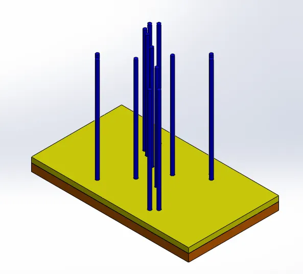
Ejector System
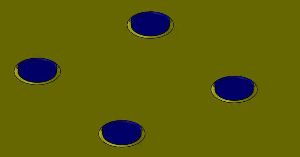
Provision to hold the pins in back plate
5. Runner and Gate System:
The Sprue is provided in the cavity block and the inlet is tapered such that it deataches from the cavity block when the core and cavity block separate. The runner and gate is created in the caore block and subtracted from the core block and fillets are provided for proper flow of the molten plastic into the cavity.
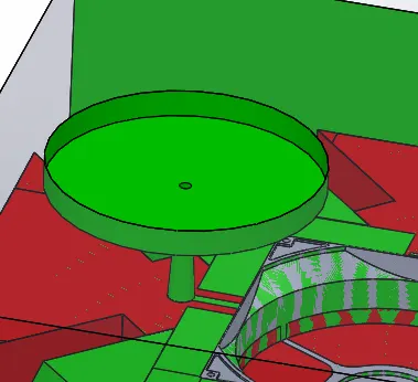
Sprue (Cavity Block)
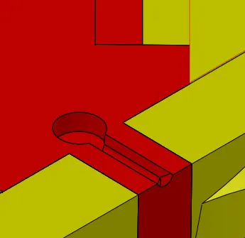
Runner and Gate
6. Air Vents:
The air needs an outlet when it is filled with the molten plastic. Hence, cooling channels are provided. The cooling channels are provided at the side from where the gate is located. A step is provided so that the plastic doesn't flow over and only air is passed through the air vent.
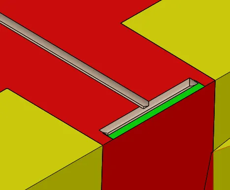
Face in fadded color (channel to guide air out); Face in green (Step provided to stop molten plastic from flowing over).
Assembly:
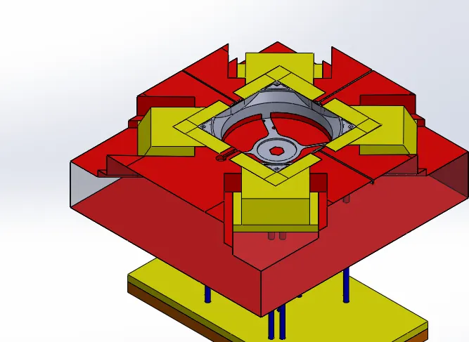
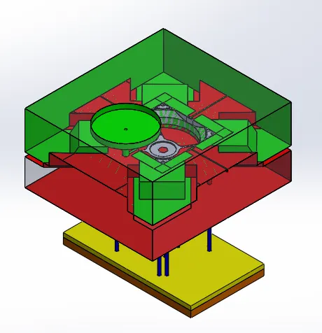
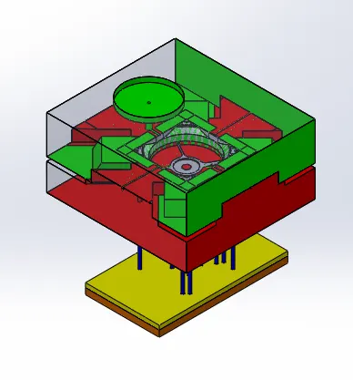
Conclusion: Thus, core and cavity blocks, sliders, ejector system, runner and gate system and air outlet are added to the mold assembly.