Project 2
Route the wiring harness on given car body and prepare flatten view drawing in Catia v5. Application of all packaging rules, Industry best practices studied in this course shall be demonstrated in design. Apply protection coverings as required.
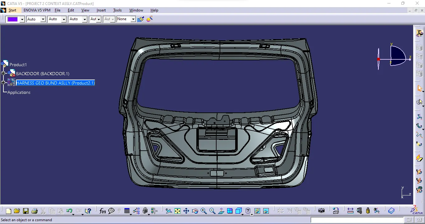
Back Door Assembly Part
Now for Construction of the Harness Assembly Bundle:
Step 1:
Create Context Assembly :-
- A Context Assembly for Backdoor Wire Harness has been created, which will work as the main assembly as shown in the figure above.
- A Context Assembly will Contain Backdoor Assembly data and Backdoor Wire Harness Geometrical Bundle assembly.
Step 2:
Positioning the Connectors & Clip/ Clamps to the Back Door Assembly:-
- C-776438 Which is a 12 Pole connector is used as an inline Connector
- C-1563689-1 Which is a Four Pole connector for Tail light and Numberplates Lighting and Power Latches.
To electrically define a connector , we must first define the geometrical parameters such as the Bundle Connection Point and the Connector Connection Point in the Electrical Part Design Workbench for the downloaded Connector.
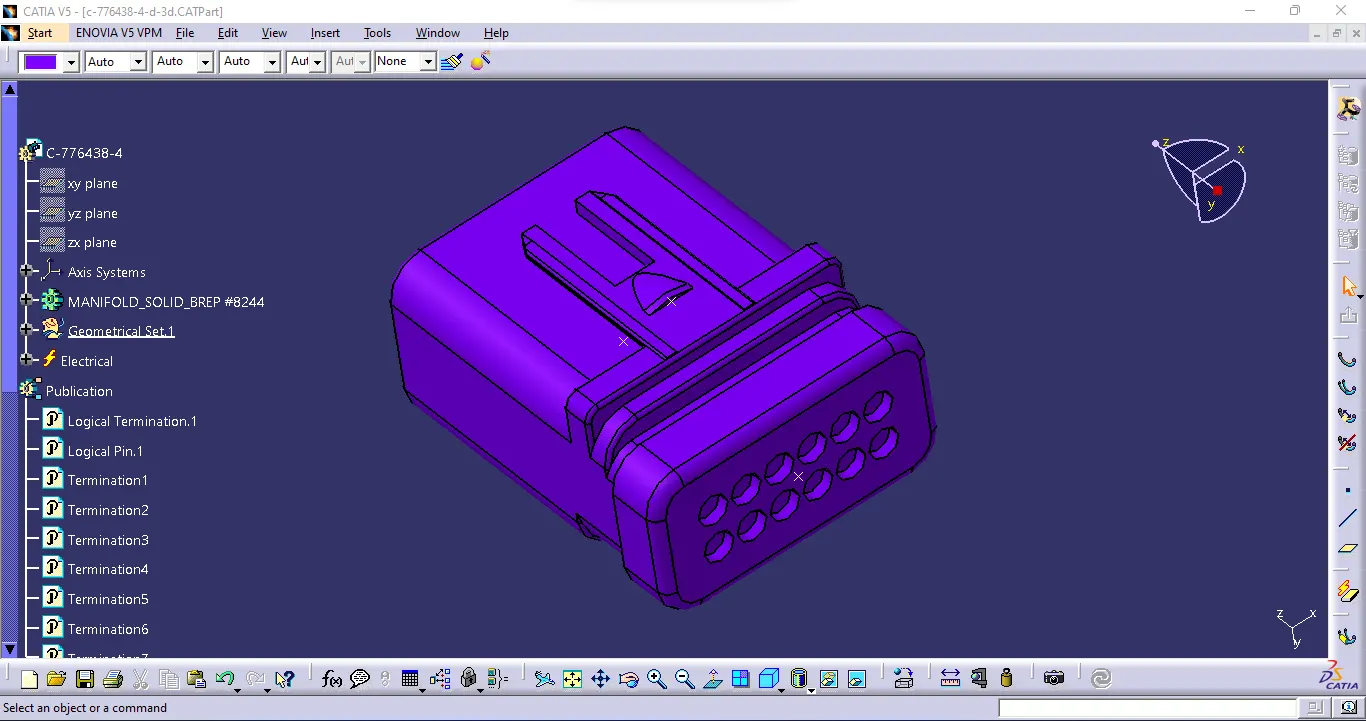
C-776438
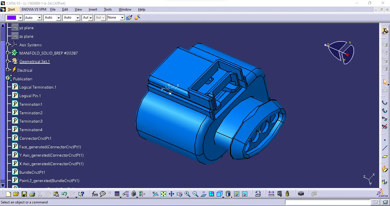
C-1563689-1
For Support,
We use Omega Clips :-
We need to mount the Omega clips on the Backdoor to provide support as well as act as a guiding channel, so we must first define it electrically with geometrical parameters, entry, and exit points on both the left and right sides of the clips, as shown in the figure below.
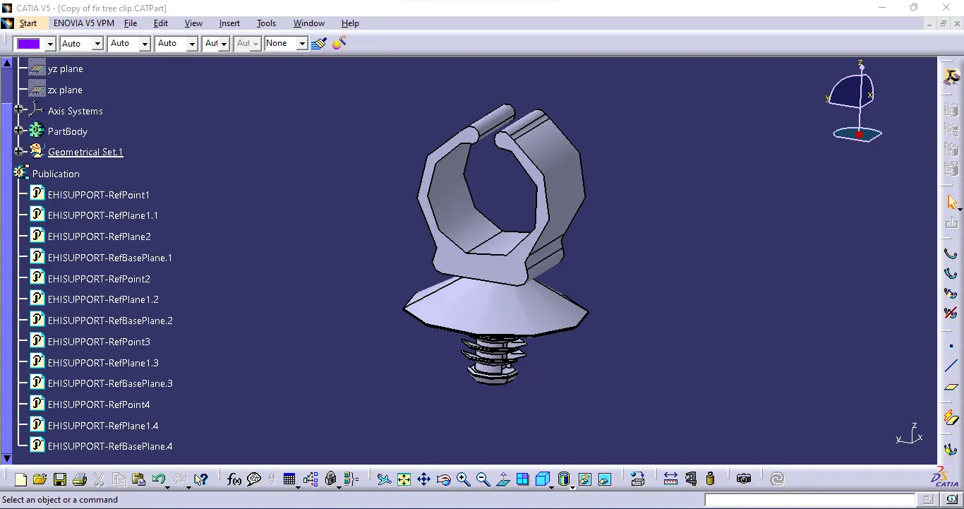
Omega clip
Step 3:
Mounting the Omega Clips and Placing the Connectors :-
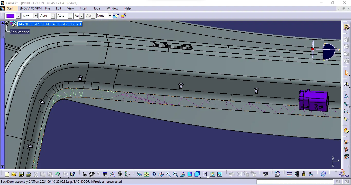
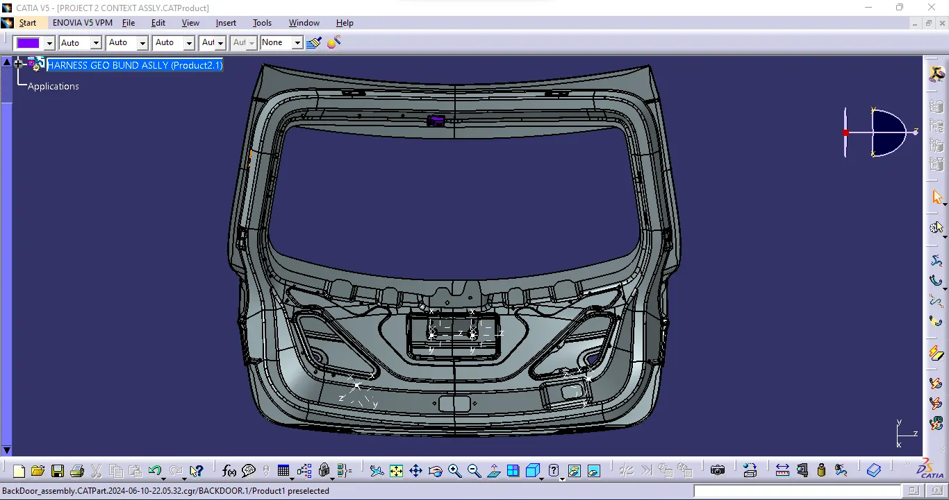
- For the placement of the Omega clips and the Connectors we used various commands such as manipulation, snap, smart move, compass, and so on.
- The entire assembly is ready for routing.
- Mounted are all connectors, Omega clips, and Interconnection connector.
Step 4:
Bundle Routing:-
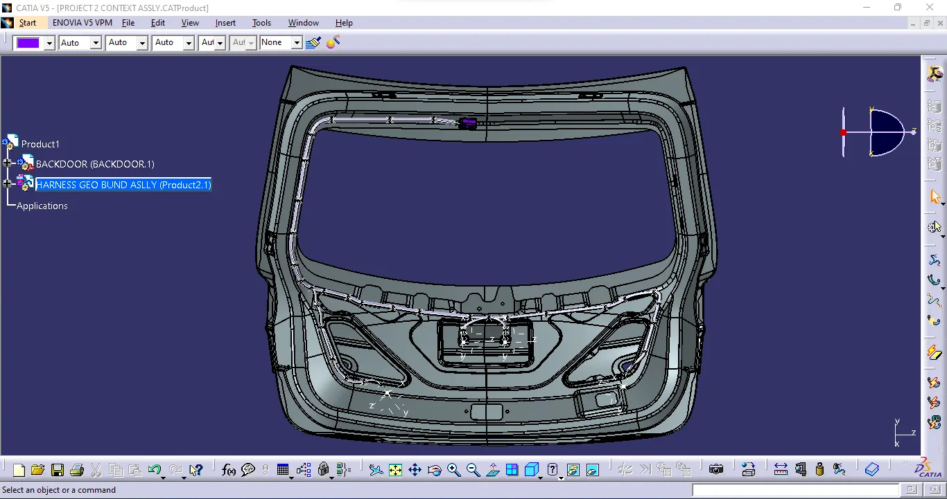
- The bundle segment is routed from the interconnection connector to the Omega clips and guided towards the other connectors. while maintaining the Bend radius ratio of 1.4.
- We have used bundle thickness 5-10mm.
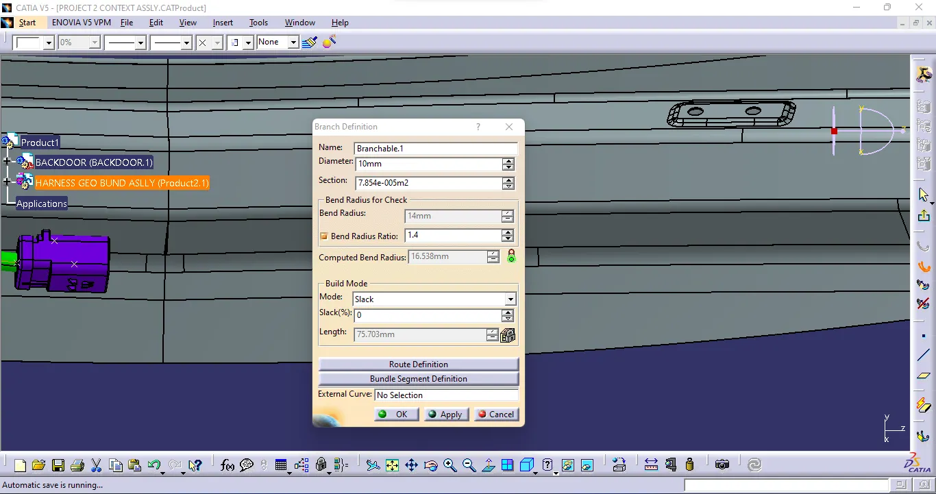
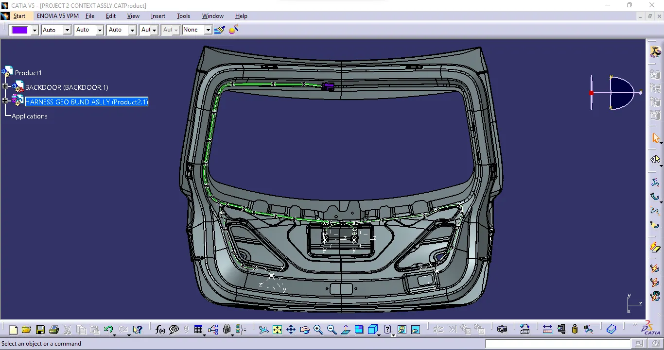
Backdoor with bundle routing
Step 5:
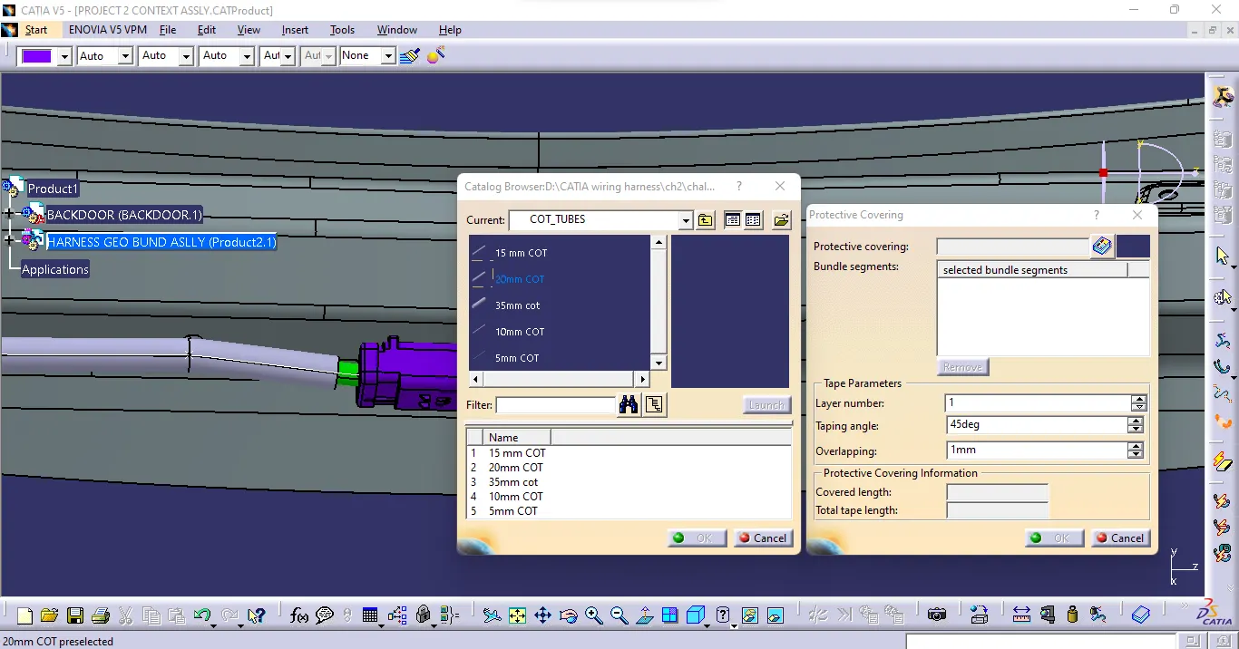
Adding protective coverings and guiding channels top shell to harness bundle :-
Here is the Above figure, we have done with the whole wiring harness routing for the Backdoor. Now, we have to add protective coverings to all bundle segments.
Step 6:
Checking bundle continuity :-
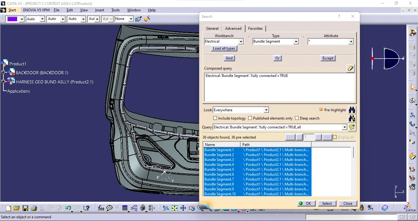
In this step, we must first ensure that multi-branch capability is selected before proceeding to Edit>Search>Advanced>Workbench-Electrical>Type-Bundle Segment>Attribute-Fully Connected.
Selecting 'True' displays all connected bundle segments while selecting 'False' displays all non-connected bundle segments.
In this case, we chose the 'True' option and searched for results. As shown in the figure below, all of the bundle segments are highlighted, indicating that they are all electrically connected.
Step 7:
Creating flatten view of the Backdoor Wire harness geometrical bundle assembly :-
- In this step, we will use Catia V5's Electrical Harness Flattening workbench to create a flattened view. We should also ensure that the flattening file is saved in the same folder as the other harness assembly files.
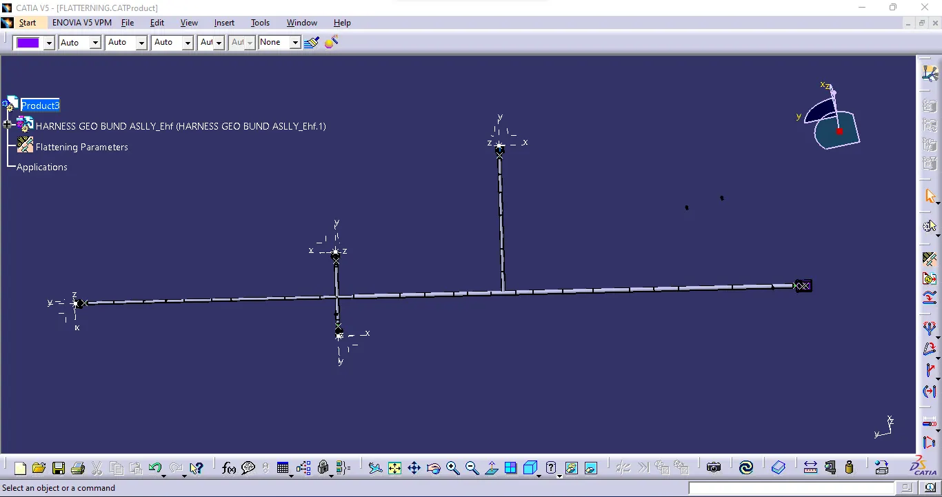
- The bundle assembly was extracted into a Back door wire Harness Flattening Product file, which was then flattened along the face of the interconnection connector.
- We developed a flattened view.
- we must rotate bundle segments connecting to the four cam-shaft connectors using the 'Rotate' feature of the flattening workbench.
- It should be noted that the 'face' of the interconnection connector serves as the flattening plane, so we must rotate the bundle segments only along that plane.
- We used various features such as bend, rotate, and roll to streamline the harness for better representation.
- The flattened view's final representation
Step 8:
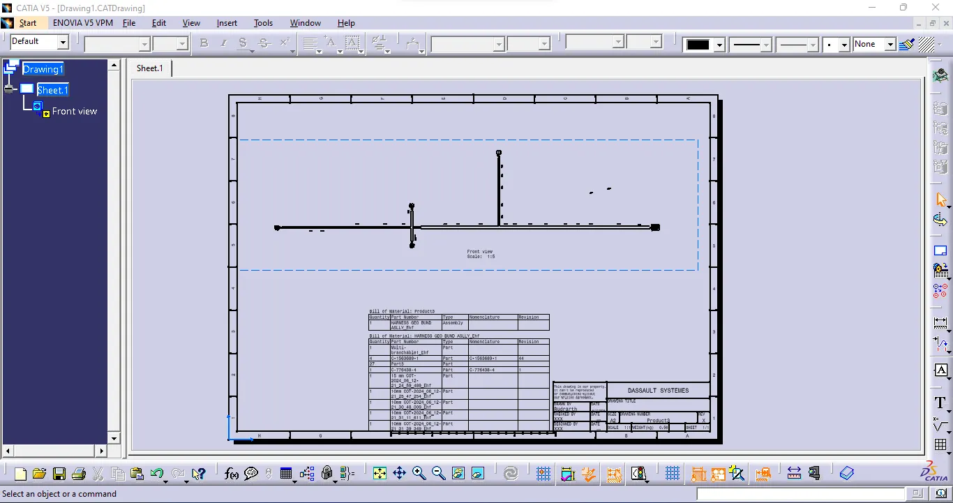
Creating a flattened view drawing for the wiring harness assembly:-
In the figure above, we're creating a new drawing file and defining all of the required drawing parameters. The front view of the Backdoor wire Harness Flattening Product file must be inserted into the Drawing file. As shown in the preceding figure, we must define drawing properties. It should be noted that the 3D wireframe is always ON in the 'Dress up settings. If this option is not enabled, the bundle segments will not be visible in the drawing view. the Backdoor wire Harness Flattens view's final Drawing view
All project related file are attached in zip folder.