Project 2
AIM:
To Route the Wiring harness on Given car body backdoor/tailgate and Prepare flatten view drawing in CATIA V5. Apply Clipping/Clamping selection, Protection coverings as required.
OBJECTIVE:
This project aims to exemplify the practical implementation of wiring harness routing and design principles on a car's backdoor/tailgate using CATIA V5 software. The primary goal is to showcase the application of industry-standard practices and packaging rules learned throughout the course by creating a well-routed wiring harness and a flattened view drawing. The project will include the utilization of suitable protection coverings and connector 3D data sourced from www.te.com to ensure a realistic and comprehensive design.
The project will emphasize the generation of essential reports, such as clearance, clipping/clamping selection, harness fixing requirements, harness continuity, and any pertinent assumptions. These reports, along with the CATIA 3D data, will be submitted to offer a comprehensive overview of the design process and the decisions made.
Successfully completing this project will demonstrate proficiency in electrical component definition, catalogue creation, proper bundle routing, support part selection, flattening, and drawing creation using CATIA V5's flattening and drafting workbenches. The project will be assessed based on the criteria outlined in the grading policy, ensuring that all aspects of the wiring harness design process for the car's backdoor/tailgate are adequately addressed and presented.
First we have to download input data
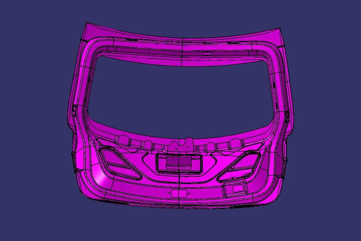
DESIGN CONSIDERATION FOR WIRING HARNESS ROUTING:
As a wiring harness designer responsible for crafting the electrical system for automotive backdoors and tailgates in modern vehicles, several crucial elements must be taken into consideration to ensure optimal functionality, longevity, and compatibility with the vehicle's electrical infrastructure. Let's explore these key considerations:
1. Electrical Requirements:
- Identify the electrical components in the backdoor/tailgate, such as power locks, windows, rear wipers, defrosters, and cameras.
- Determine the power requirements for each component, including voltage, current, and peak loads.
- Consider the use of advanced features like gesture-controlled tailgates, proximity sensors, and anti-pinch technology.
2. Connector Selection:
- Choose appropriate connectors based on the electrical requirements, environmental conditions, and space constraints.
- Consider using sealed connectors to prevent water and dust ingress, ensuring reliable connections in harsh environments.
- Evaluate the use of high-speed data connectors for cameras, displays, and other advanced features.
3. Wire Selection:
- Select wire gauges based on the current-carrying capacity and voltage drop requirements of each circuit.
- Use high-temperature, abrasion-resistant, and flexible wires to withstand the harsh environment in the backdoor/tailgate area.
- Consider using shielded wires for sensitive circuits to minimize electromagnetic interference (EMI).
4. Routing and Packaging:
- Design the harness routing to minimize the risk of chafing, pinching, and stretching during door/tailgate movement.
- Utilize protective sleeves, conduits, and grommets to protect wires from sharp edges and moving parts.
- Optimize the harness layout for easy installation, and serviceability, and to minimize the overall weight and cost.
5. Modularity and Scalability:
- Design the harness with modularity in mind to accommodate different trim levels and optional features.
- Use standardized connectors and interfaces to enable easy integration of additional components or future upgrades.
- Consider the use of subassemblies or pre-terminated cables to simplify the assembly process and reduce installation time.
6. Safety and Compliance:
- Ensure the harness design complies with relevant automotive standards, such as ISO, SAE, and FMVSS.
- Incorporate safety features like short-circuit protection, overcurrent protection, and proper insulation.
- Conduct thorough testing to validate the harness's performance, durability, and resistance to environmental factors.
7. Vehicle Integration:
- Collaborate with the vehicle design team to ensure proper integration of the harness with the backdoor/tailgate structure and mechanisms.
- Consider the impact of the harness on the vehicle's weight distribution, centre of gravity, and overall performance.
- Evaluate the need for additional support brackets, cable ties, or adhesives to secure the harness in place.
8. Manufacturing and Assembly:
- Design the harness with manufacturing feasibility in mind, considering aspects like wire routing, connector orientation, and assembly sequence.
- Optimize the harness design for automated assembly processes, such as wire cutting, crimping, and connector insertion.
- Develop clear and concise assembly instructions and diagrams to ensure consistent and error-free production.
9. Testing and Validation:
- Perform rigorous testing to validate the harness's functionality, durability, and reliability under various operating conditions.
- Conduct environmental tests, such as temperature cycling, humidity exposure, and vibration testing, to ensure the harness's performance in real-world scenarios.
- Verify the harness's compatibility with the vehicle's electrical system through integration testing and on-vehicle validation.
10. Cost and Supplier Management:
- Collaborate with suppliers to identify cost-effective materials and components that meet the harness's requirements.
- Evaluate the use of alternative materials or manufacturing processes to optimize cost without compromising quality.
- Establish strong relationships with reliable suppliers to ensure consistent quality, timely delivery, and technical support.
By considering these factors and incorporating the latest technologies and design practices, a wiring harness design engineer can develop a robust, efficient, and future-proof backdoor/tailgate wiring harness for newer vehicles in the market.
PACKAGING RULES:
- Routing should facilitate ease in manufacturing, accessibility, removal, and maintenance of attached equipment and wiring harnesses.
- Avoid routing through small structural holes and openings to minimize chafing and handling during installation.
- Avoid routing and clipping in the blind zone of the operator during harness assembly or service.
- Protect against potential damage caused by common misuses, such as being handheld or used as temporary support for test equipment.
- Allow additional slack in the harness according to the surroundings and bending requirements.
- Ensure routing meets clearance requirements with different surrounding parts.
- Provide sufficient slack for each branch to avoid additional stress on the wire and terminal crimping joint, while preventing harness fouling due to extra slack.
- Avoid routing over bolts or near bolted joints to prevent harness damage or puncture. Keep harnesses away from panel mounting screws.
- Provide protection when routing near sharp edges is unavoidable.
- Maintain a maximum distance of 200mm between two clips on a straight branch.
- Use clips and clamps if the harness bends at multiple locations.
- Minimize the use of sheet-metal brackets.
- Ensure branch lengths are greater than 50mm.
- Maintain a minimum distance of 25mm between the clip and the branching point.
- Keep a minimum distance of 50mm between two branch breakouts.
- Use rubber grommets when the harness passes through sheet metal panels.
- Elevate the harness connectors above the routing and branching locations to mitigate potential water ingress caused by gravitational forces.
CONNECTORS, CLIPS AND CLAMPS USED IN ROUTING:
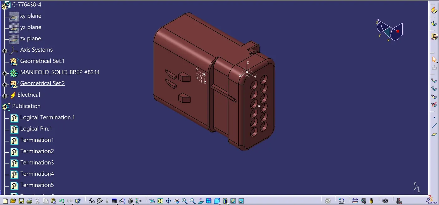
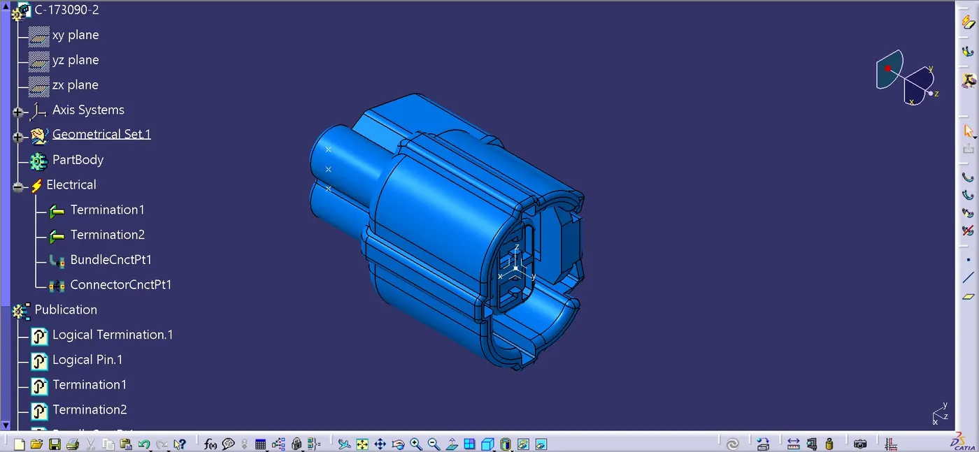
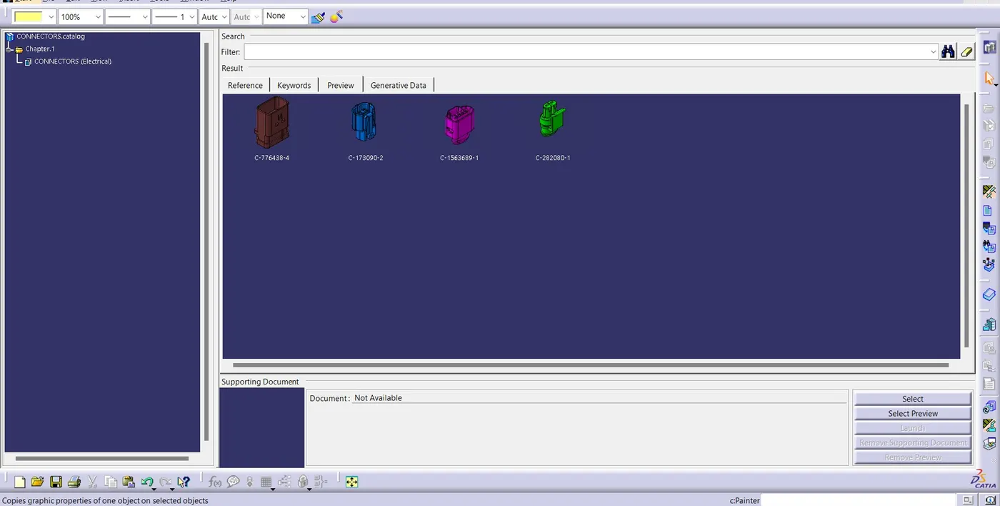
Download the required Connectors from the source and convert the mechanical connectors electrically by using the electrical part design work bench by following below steps.
- First download the connectors and mounting clip from the given link source.
- Get into the mechanical part workbench to create required geometrical parameters. Create connector connection point and bundle connection point on the required sides of the CAD part.
- Create axis system on the connector connection point such a way that the Y coordinate facing normal to the connector face, X coordinate facing towards the locking mechanism and Z coordinate facing to the top.
- Create cavity connection point for connectors having the cavity for mounting clips.
After create the geometric parameters on the connector. we have to define the connector as electrical by creating:
- Define part as electrical connector.
- Define bundle connection point.
- Define connector connection point.
- Define cavity connection point.
C-776438-4:
C-173090-2:
C-282080-1:
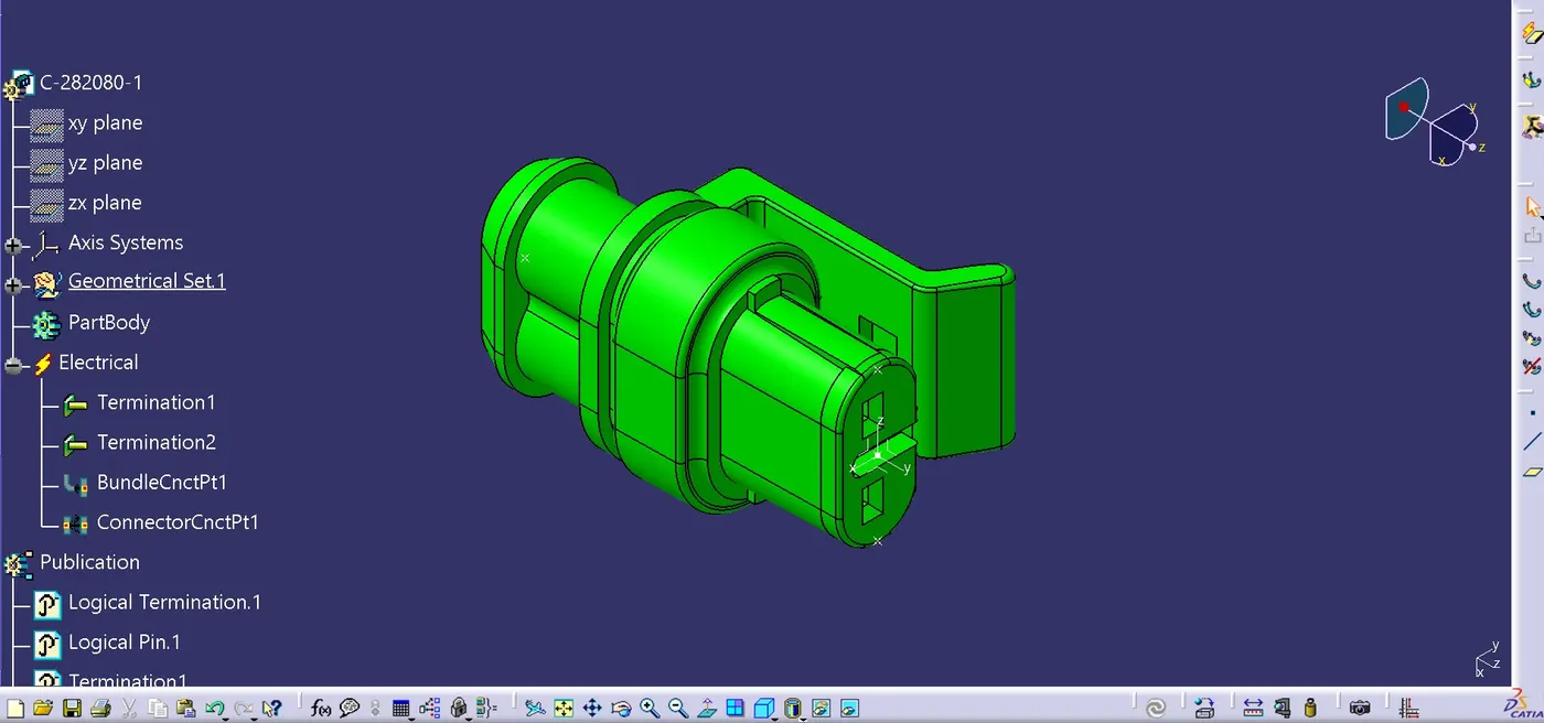
After that add the all connector into the catalog
Download and Define the P-clamp, L-clamp, guiding channel and cavity clip electrically.
- Define the Channel electrically.
- Establish bundle entry and exit points.
- Form a curved line between the main entry and exit points to allow for multiple branches within the channel.
- Set up 8 bundle entry points on the openings to accommodate the injector connectors.
- Utilize geometrical parameters to electrically define the channel by employing the "define mounting equipment" option.
- Establish bundle connection points using the "define bundle connection point" option.
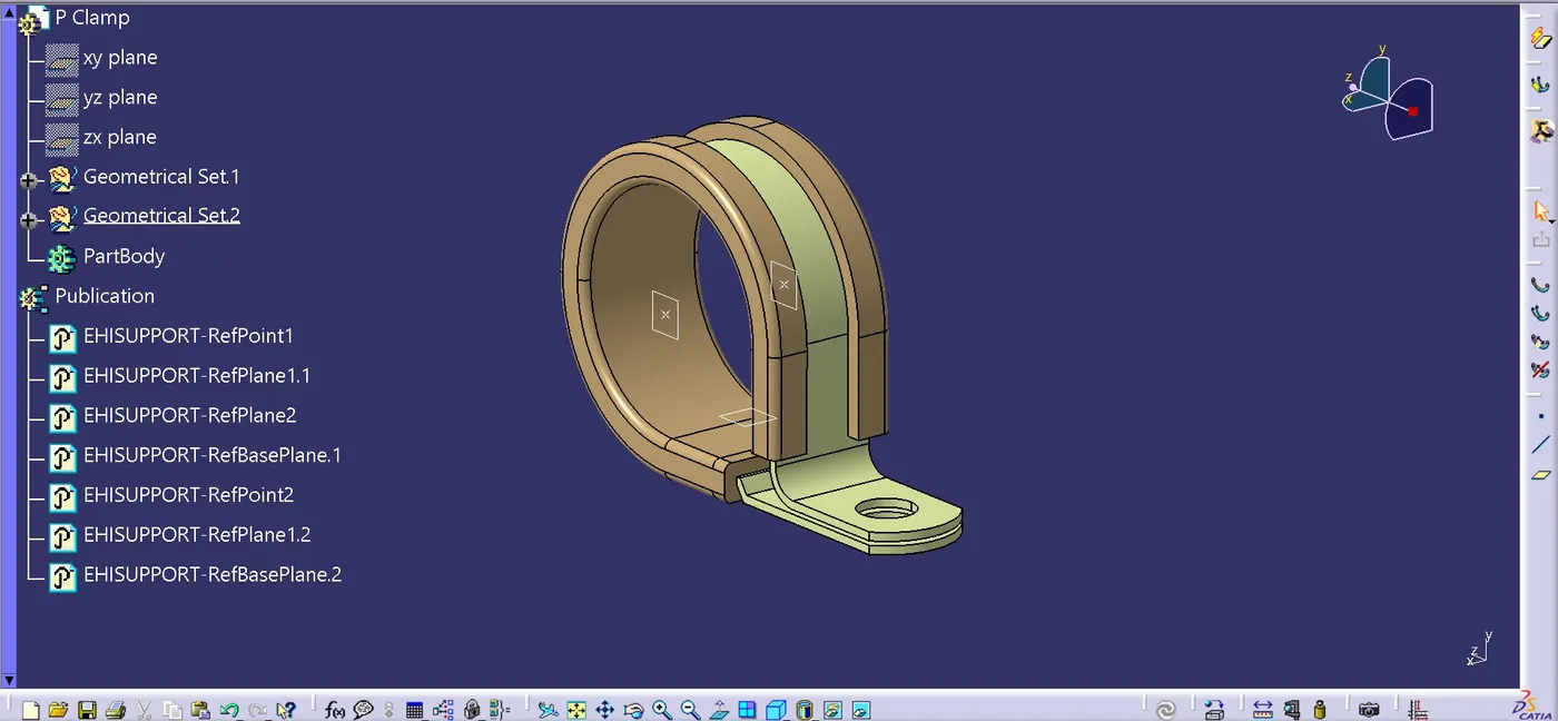
P-CLAMP:
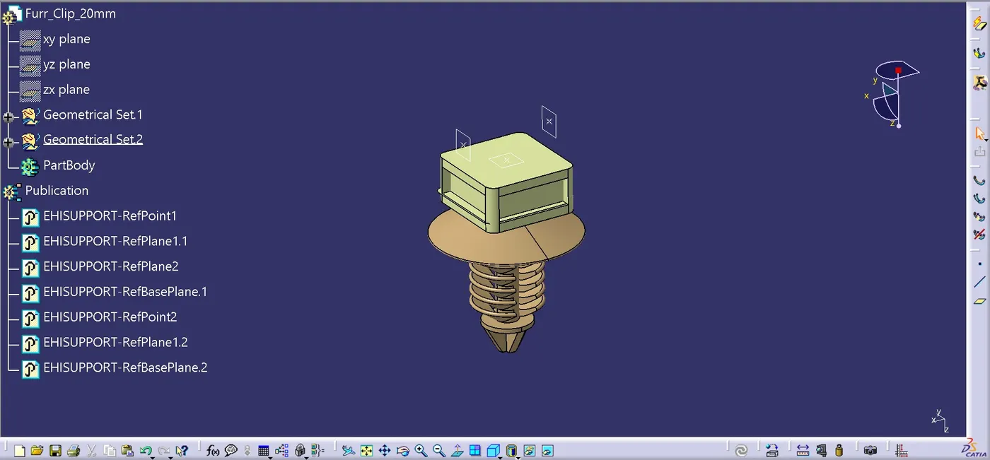
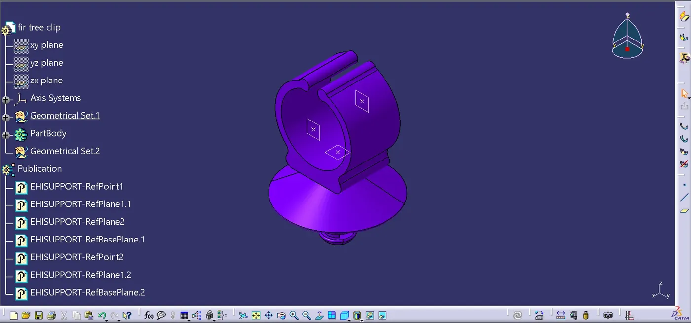
FIR TREE CLIPS:
GENERATING THE CONTEXT ASSEMBLY:
Context assembly is nothing but the product file which contains the engine 3D-CAD data and the engine harness geometrical bundle. Here the geometrical bundle product contains all the connectors and other mounting equipments, clips and clamps which are electrically defined for the assembly.
A context assembly is a top-level product file within the CATIA V5 environment. It serves as the central container for all the components that constitute the wiring harness.
It typically encompasses three main sub-assemblies:
Geometrical Bundle: This sub-assembly defines the physical layout of the wiring harness within the vehicle. It includes the actual routing of the wires, connectors, clips, clamps, and other supporting features.
Electrical Bundle: This sub-assembly contains all the electrical data associated with the harness. This includes information on wire gauge, colour coding, pin assignments, and connector specifications.
Annotations: This sub-assembly holds any notes, comments, or additional information relevant to the wiring harness design.
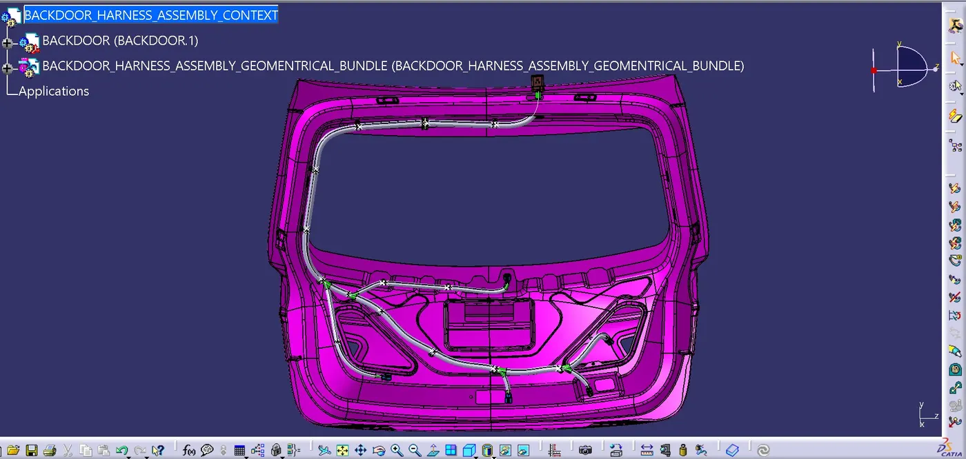
In CATIA, we will initiate the design process by establishing a new product. This product will function as the context assembly and serve as the central hub for managing all data about the backdoor wiring harness.
Next, We'll access the dedicated wiring harness product by double-clicking it. Then, using a right-click, we'll open it in a separate CATIA window for focused routing and packaging.

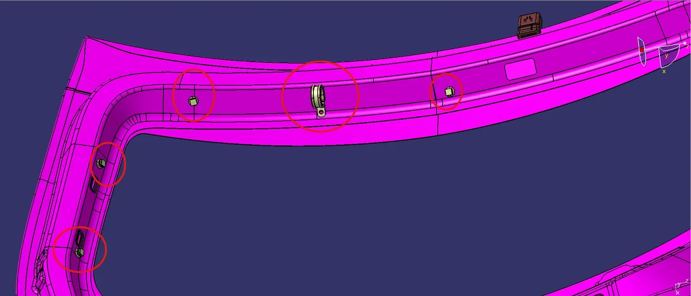
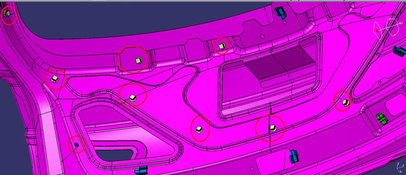
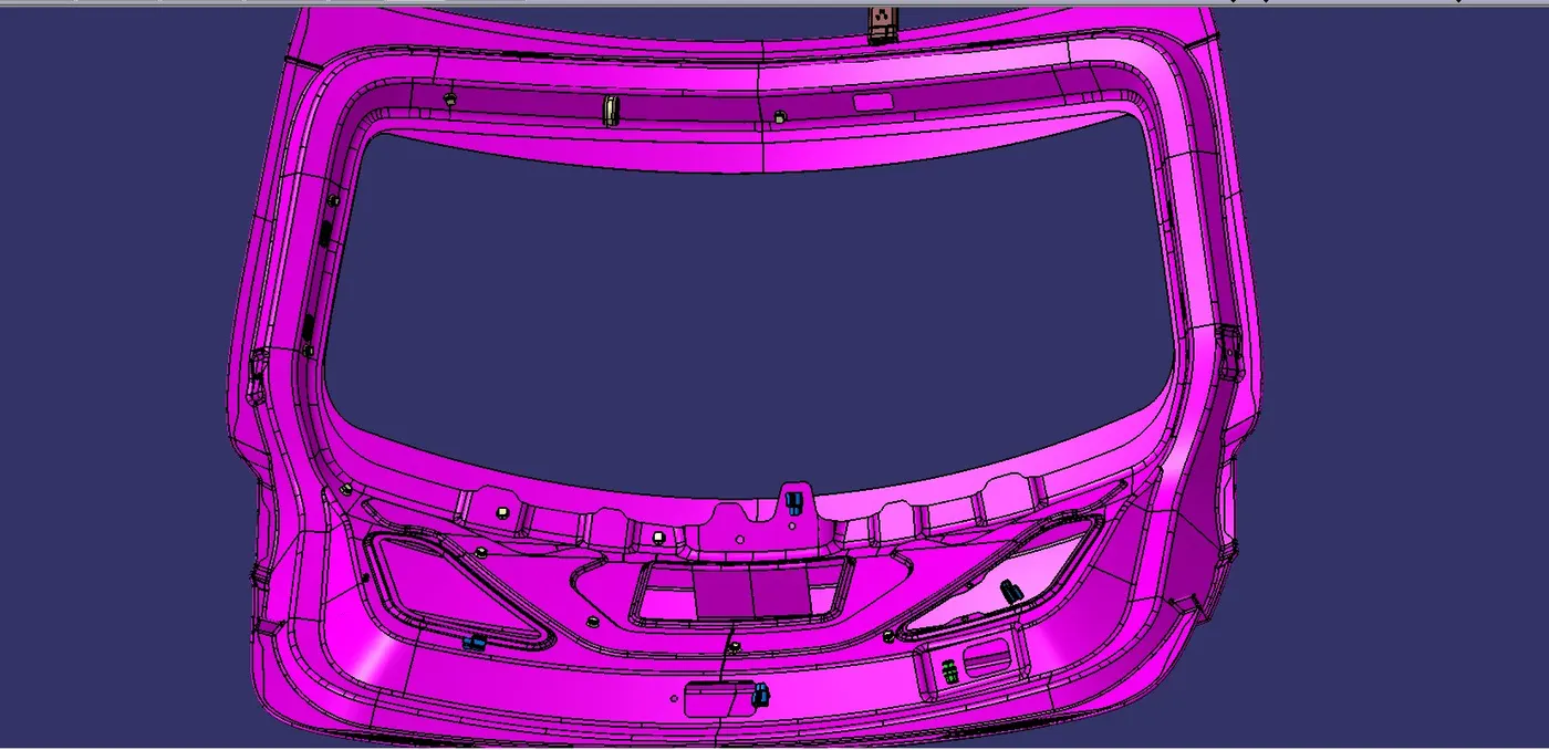
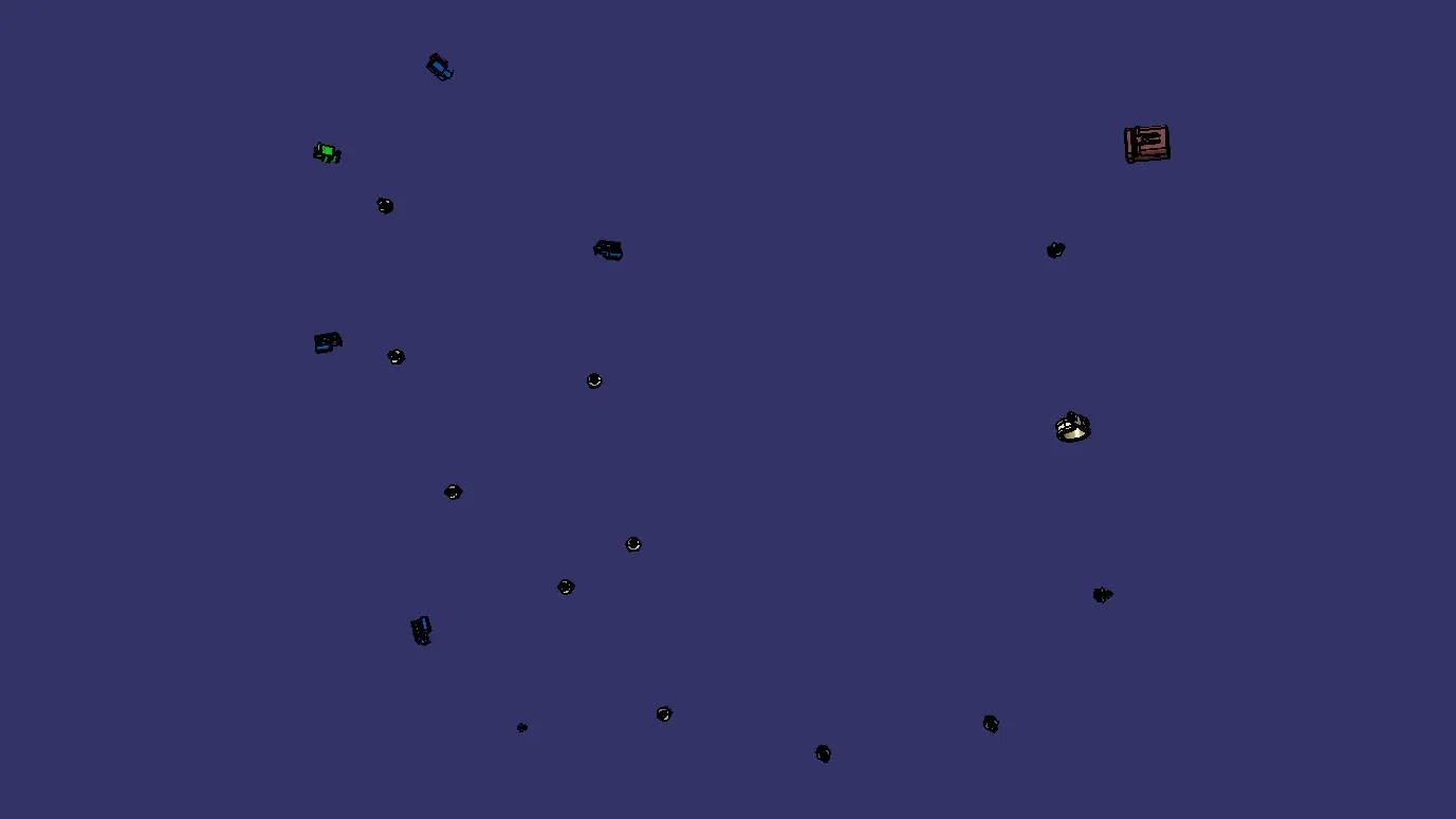
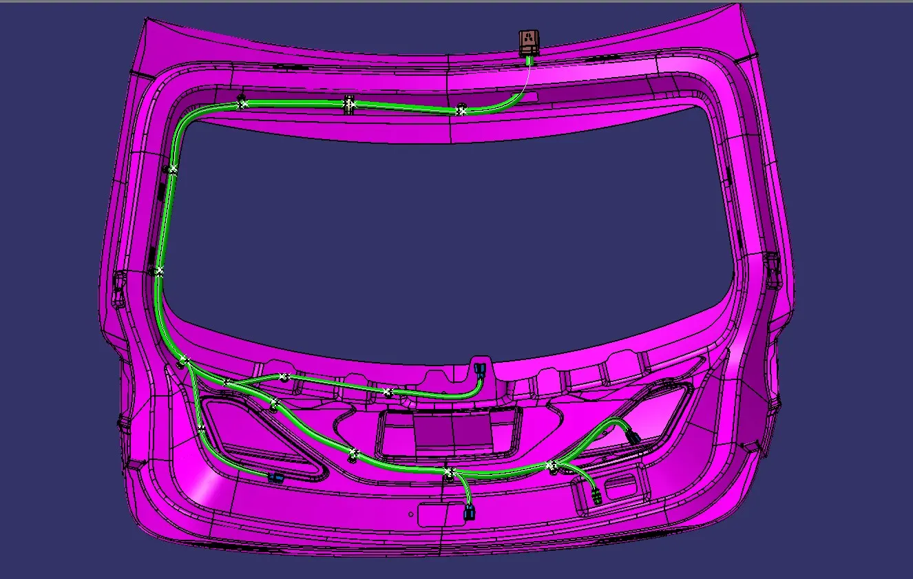
For given back door assembly model requires total number of 6 connectors. we see one by one where it will be placed in the back door.
First interconnection connector on the top.
However, situation of interconnection connectors are not similar to device connectors. Interconnection connectors are not parked with any device but should be pared with the help of clips/clamps/sheet metal brackets etc. possible to the packaging conditions.
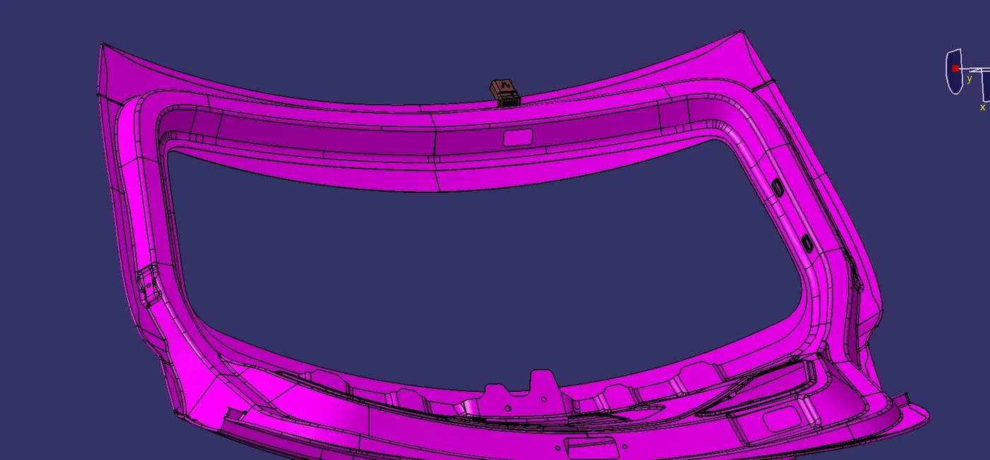
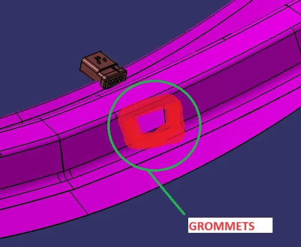
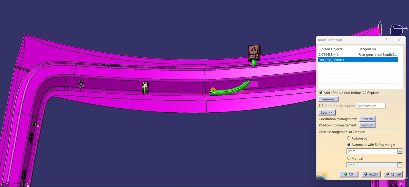
For this we have make the cut out in the top of the backdoor for routing with the other connector. while we make the cut we should add the grommets for that cut out. image mention below.
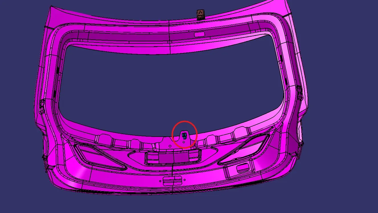
Next connector for backdoor viper
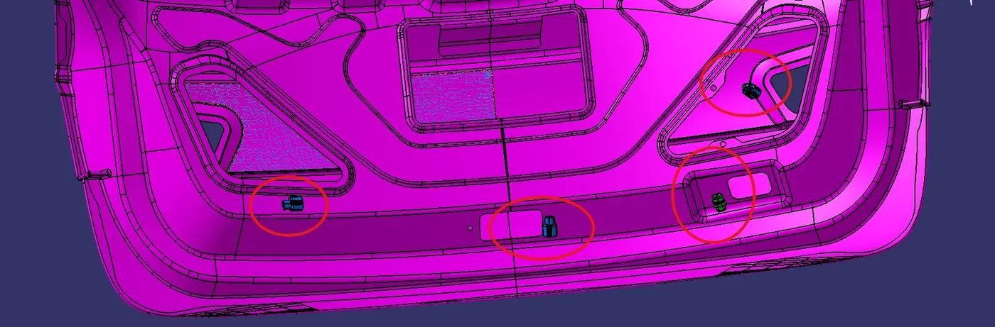
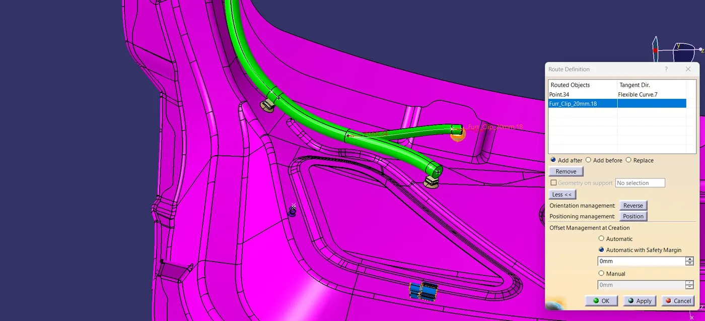
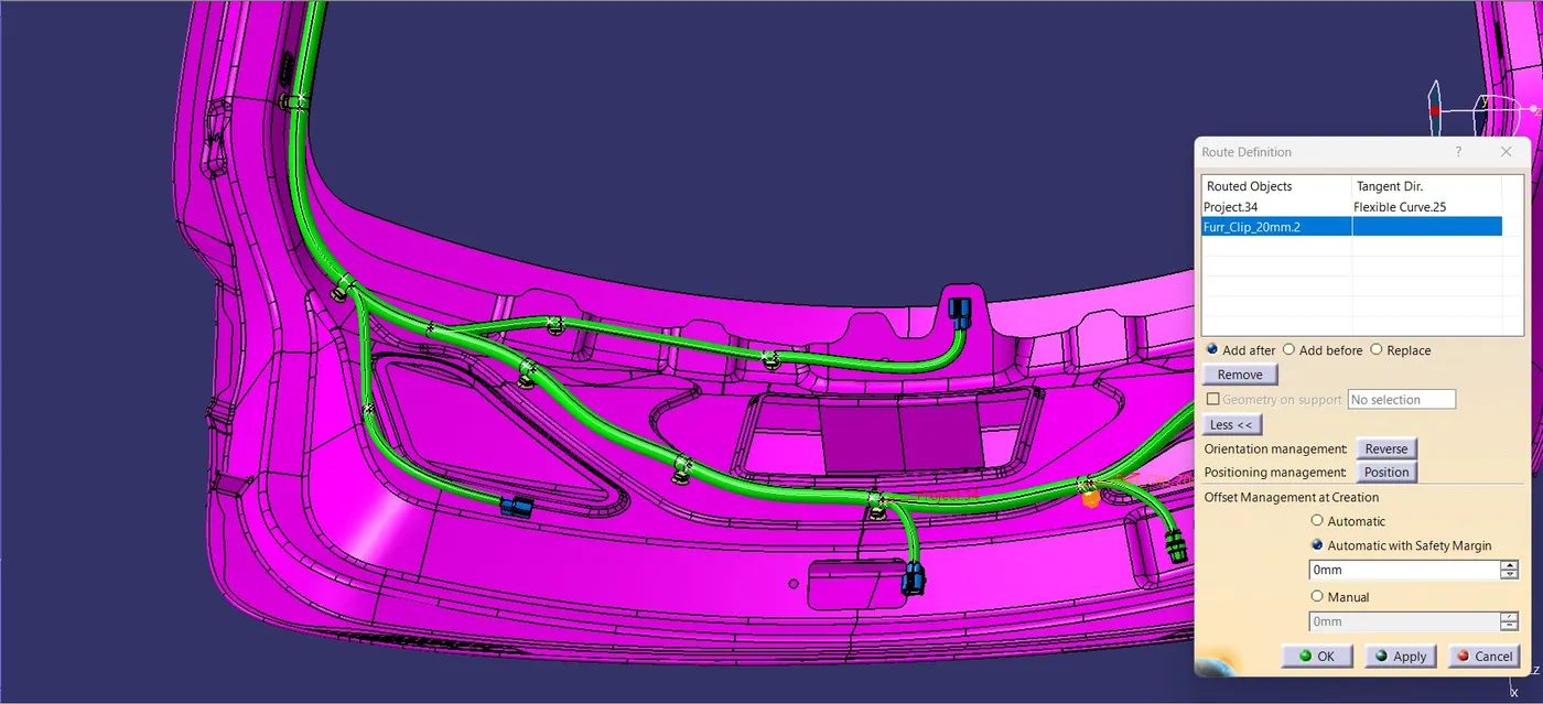
For next four connector one for Back door light and other for latch mounting and other for lamp in the back door. image mention below.
On the other hand we have add the clip and clamp.
Add P-clamps for proper Routing of the harness bundle.
P - Clamp and the Fir Tree clips can be placed at required locations to ensure best possible routing for the harness bundles.
The p – Clamps can be mounted to the holes provided on the Engine block in which the screws to tighten the Engine block.
The Fir tree clips are positioned according to the requirement during the wire harness routing.
After finalization of the routing, we can request the Engine design team to provide the holes for the Fir tree clips as per their location.
Adding supporting components like p-clamps and firtree clip can help the harness bundle provide proper routing and also help to prevent the harness bundles fouling from unwanted mechanical components.
After placing the connectors and clip let's move on to routing process.
WIRING HARNESS ROUTING:
For routing we should follow some important assumption:
- Provide clips/clamps as required and use additional clips/clamps to avoid falling cases.
- Allow 5-10% slack if needed.
- Avoid routing over bolts and bolted joints to prevent harness puncture.
- Provide protection when routing on sharp edges.
- Adhere to clearance distances and keep the harness away from heat-generating components.
- Protect according to the surrounding temperature.
- Avoid direct support for harnesses on fuel lines routed in the engine.
- Use plastic guiding channels if necessary.
- Maintain branch lengths greater than 50mm.
- Keep a minimum distance of 50mm between two branch points and 25mm between the clip and the branch point.
- Minimize the use of sheet metal brackets on the engine, utilizing available threaded bosses or requesting them.
- Ensure the wiring harness is easy to assemble and access.
- When using dummy connectors, ensure that the defined positions are practical, and bundle diameters and placements are properly defined for wire harness routing.
- Consider creating a harness channel for routing and protection in tight packaging areas with numerous constraints.
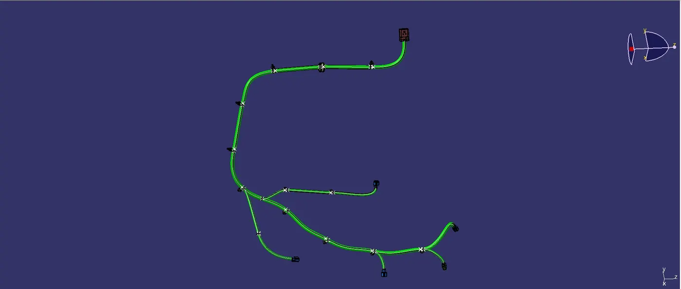
Then we will create the branches to connect the different connectors with one another by selecting the Multi-Branchable Document option from the toolbars and the giving the values of branch diameter, bent radius, and slack% in the dialog box.
Manufacturing and Assembly Considerations:
The Multibranchable option also has implications for manufacturing and assembly processes. By clearly defining and organizing the branches within the harness, we provide clear instructions and guidance for the production team.
Each branch can be manufactured and assembled separately, allowing for parallel processing and potentially reducing overall production time. The modular nature of the branches also simplifies troubleshooting and maintenance tasks.
In summary, clicking on the Geometrical Bundle and selecting the wiring harness routing file in CATIA V5 establishes a crucial link between the logical definition and the physical representation of the harness. This binding process ensures synchronization, and consistency, and enables the routing and path definition of the harness within the vehicle's geometry.
Furthermore, activating the Multibranchable option allows for the creation and management of multiple branches within the harness, introducing flexibility, modularity, and a more realistic representation of the harness structure. It facilitates the design of complex harnesses, promotes efficiency in the design process, and provides clear guidance for manufacturing and assembly. image mention below.
Applying Corrugated Tubes as Protective Coverings:
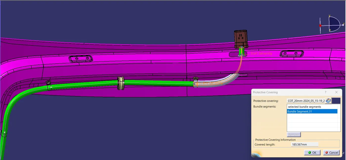
Protective coverings will be applied to specified segments of the wiring harness bundles to ensure optimal performance and protection within the backdoor assembly. Two types of corrugated(COT) tubes have been selected for this application. The first type features a 5mm inner diameter and a 6.5mm outer diameter, while the second type has a 10mm inner diameter and a 12.5mm outer diameter.
The wiring harness routing has been meticulously designed to accommodate the specific requirements of the backdoor assembly. The placement of the COT tubes has been strategically determined to provide maximum protection for the wiring harness while maintaining ease of installation and serviceability.
The selection of COT tube dimensions has been based on a thorough analysis of the wiring harness requirements, taking into account factors such as wire gauge, current capacity, and environmental conditions.The 5mm inner diameter COT tube will be utilized for smaller gauge wires and lower current applications, while the 10mm inner diameter COT tube will be employed for larger gauge wires and higher current applications.
The use of COT tubes in this backdoor wiring harness design provides several advantages, including enhanced abrasion resistance, improved flexibility, and increased durability. These attributes ensure that the wiring harness will maintain its integrity and performance throughout the intended service life of the vehicle, even under demanding operating conditions.
After finally completing the wire harness routing by following the packaging rules we need to provide protection parts wherever necessary.
Slit- COT tubes, cotton tapes are added on the wiring harness bundle. The top part of the plastic guiding channel will also be added at this stage.
We will then add protective covering on all the branches connected to the connectors by selecting the Protective Covering option from the toolbars and then selecting the branch on which we want to add the covering and then browse for the required covering from the catalog browser option and then adding it to the branch.

ELECTRICAL BUNDEL CONTINUITY CHECK:
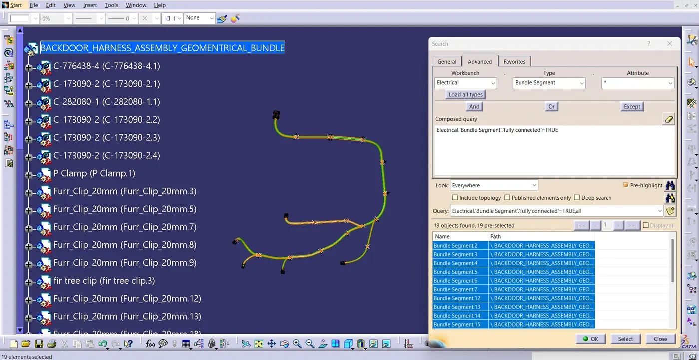
- We need to ensure that the entire bundle is fully connected.
- Go to edit and then click on search command.
- Go to advanced
- Select workbench as electrical, type as bundle segment and attribute as Fully connected
- The select result should be as TRUE or FALSE and the click search to see the connectivity analysis result.
Edit>Search>Workbench-Electrical>Type-Bundle segment>Attribute-fully connected.
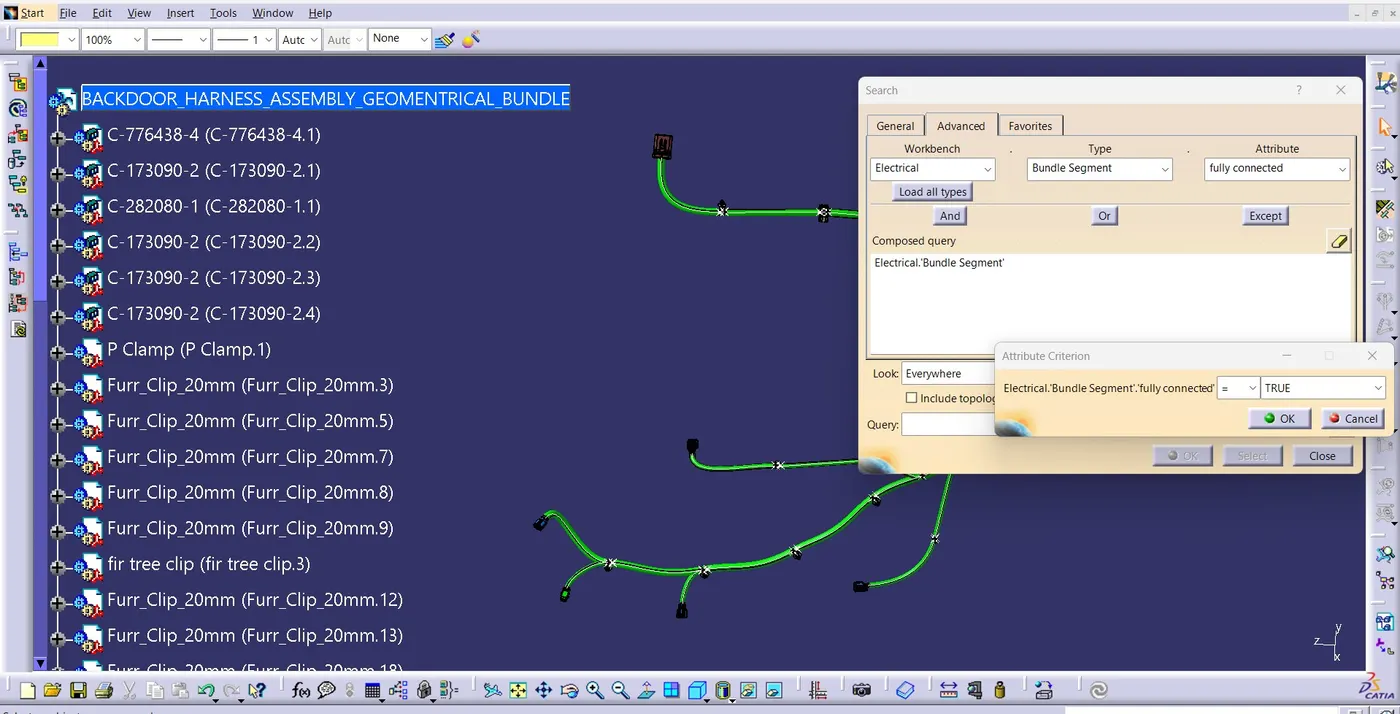
Selecting the "TRUE" option will show all the connected bundle segments while the selecting "FALSE" will show all the non-connected bundle segments.
For now, we will select "TRUE" and search for results. All the bundle segments are highlighted and found showing that all the bundle segments are electrically connected.
WIRING HARNESS FLATTENING:
From this assembly we have to do the bundle flattening.
- Create a new product file in Catia.
- Start the Electrical Harness Flattening Workbench and select the Harness Flattening Parameters option from the toolbars.
- A Harness Flattening Parameters dialog-box will appear and we have to set out our required parameters.
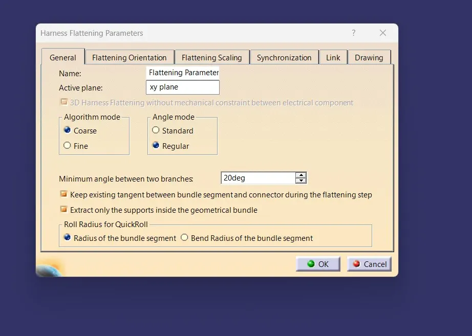
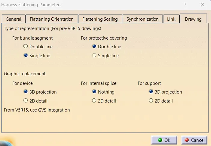
Update the setting as mention in the above image.
After that,
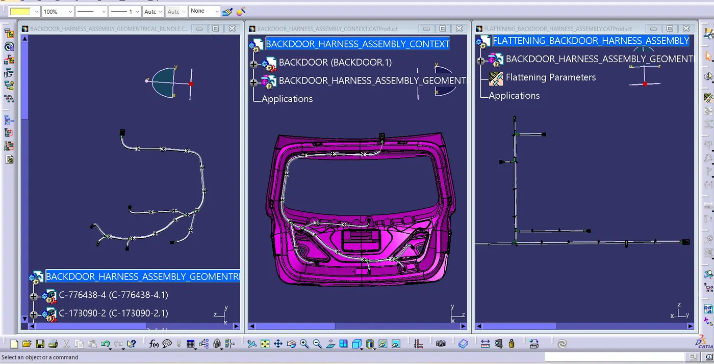
create the product > Switch to Electrical Flattening Workbench > Create the flattening Parameter
By using windows vertically > Extract command > to extract the Geometrical Bundle in to the Flattening Product.
Then we have to open our previous product file of the Wiring Harness Assembly and then go to the Electrical Harness Flattening Workbench.
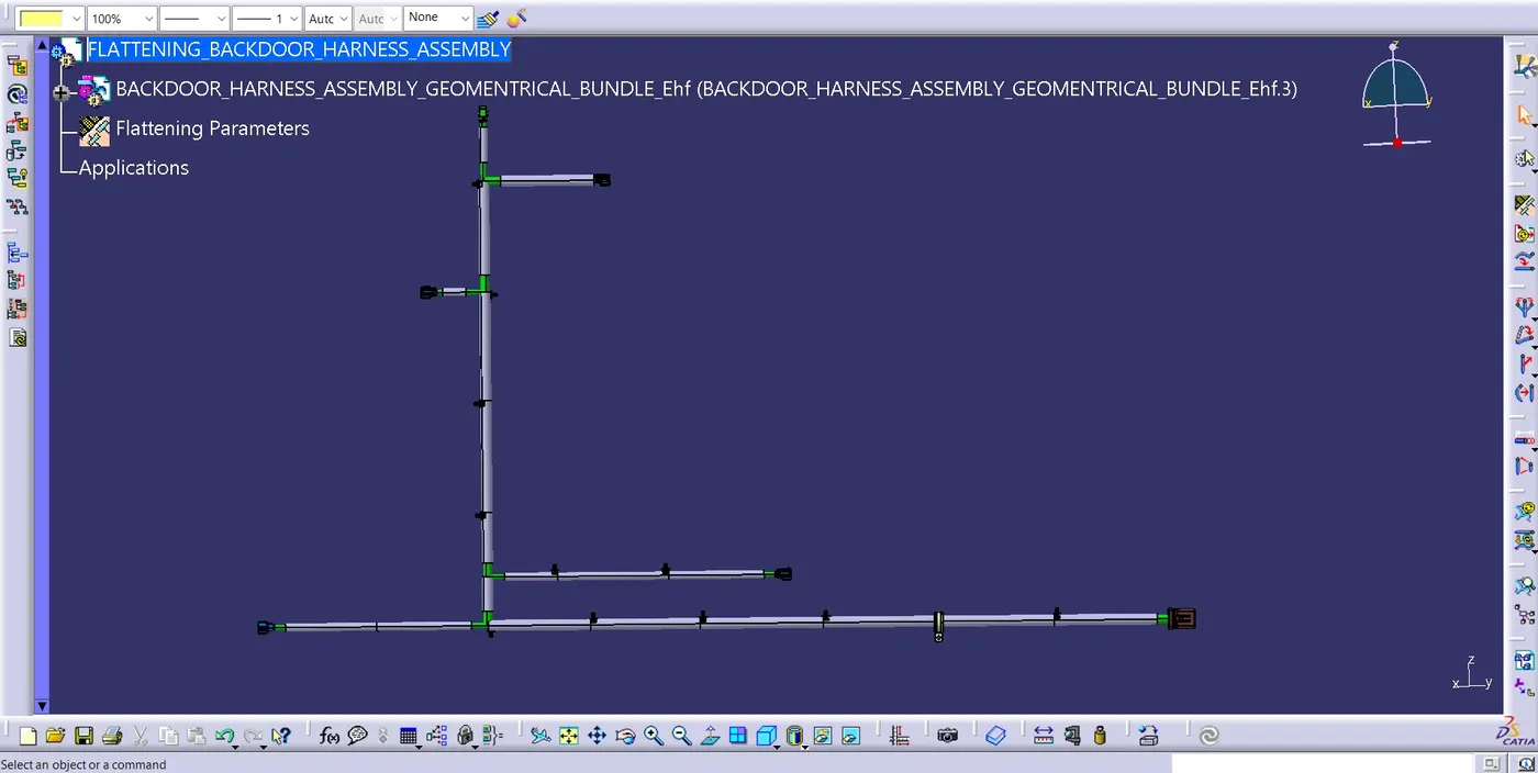
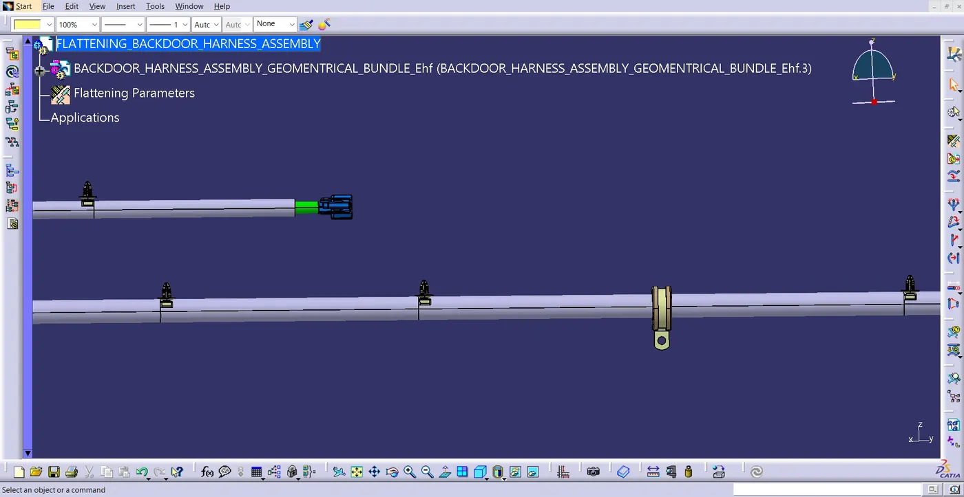
Select the Extract option from the toolbars and then if our assembly is fully connected then the file gets extracted to the second product file. If our file fails to extract then that means that our assembly is not fully connected then in that case we have to check our connections bundle continuity again.
After that we have to select the Flatten option from the toolbars and then select any face of our assembly with respect to which we want to flatten our assembly and then select all oue wire bundles and click ok. Our harness assembly then gets converted into a flattening.
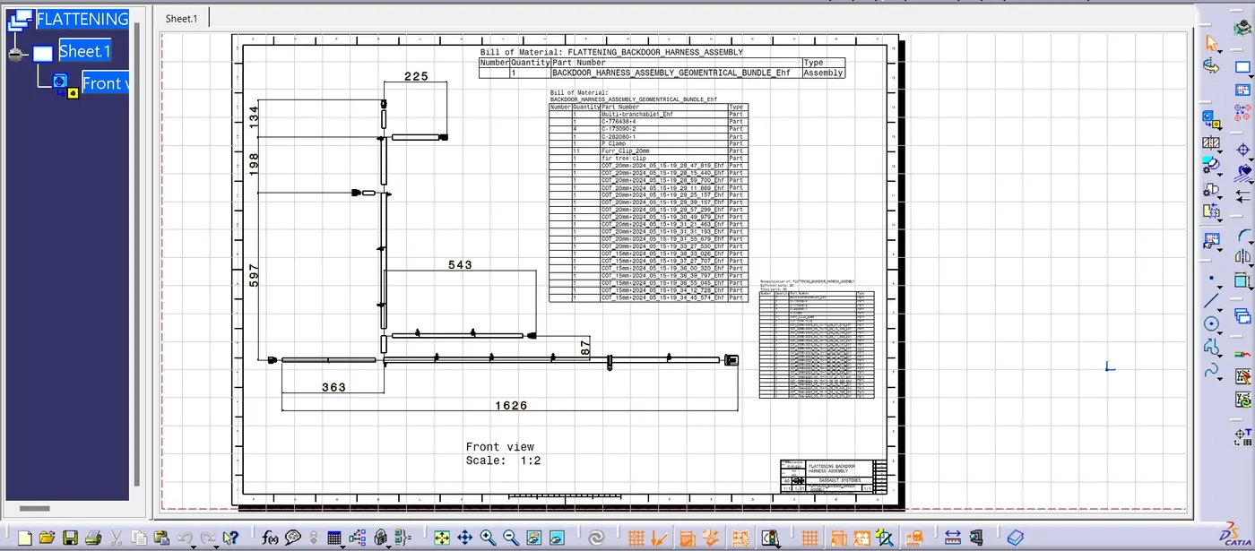
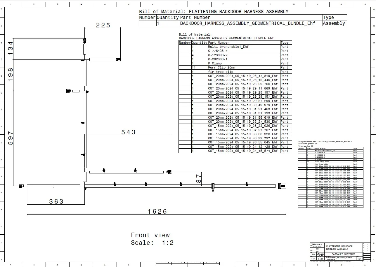
FLATTENED HARNESS VIEW ON THE DRAWING SHEET:
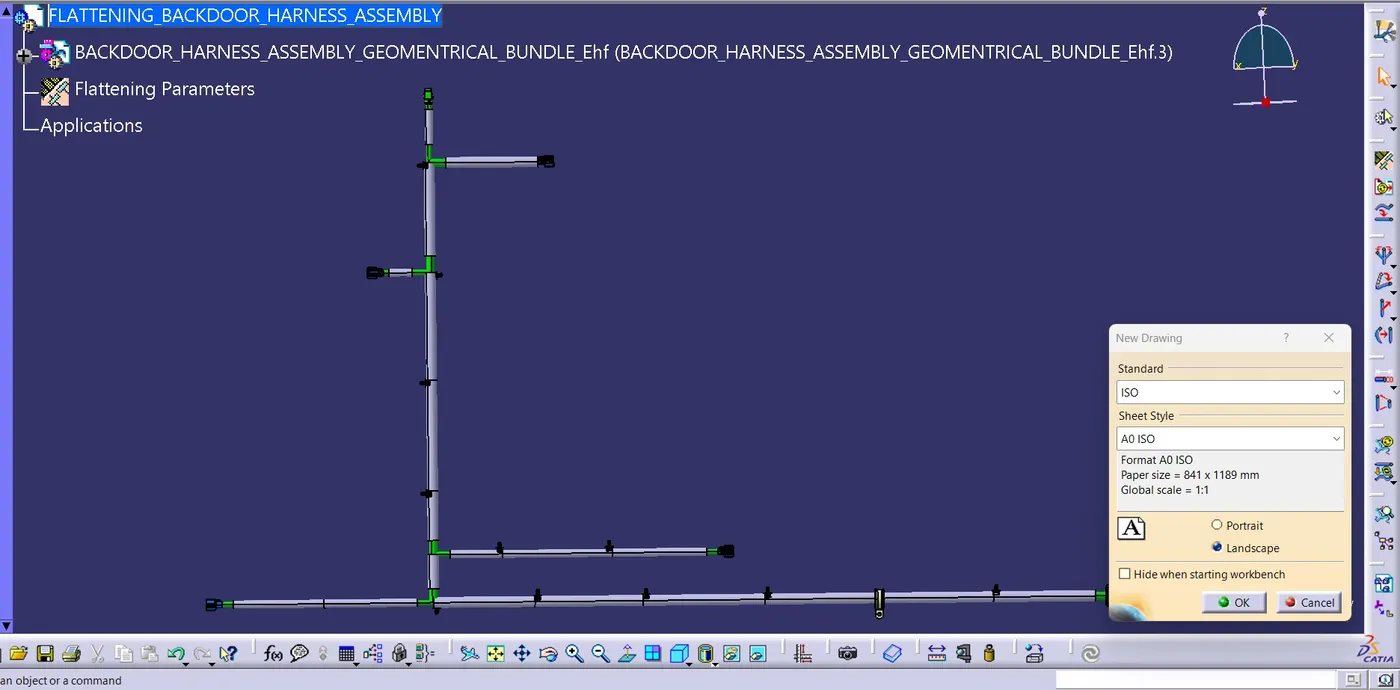
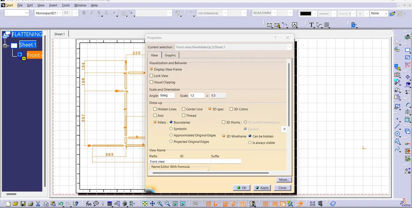
First, we need to make sure that in the flatten parameter settings bundles and protective coverings have different graphical representation which are,
- Bundle Segments – Single line representation
- Protective coverings – Double line representation.
Create a new drawing file in the drafting workbench.
CONCLUSION:
In this project We have successfully routed the wiring harness for the Given car body backdoor/tailgate and Prepare flatten view drawing in CATIA V5. Apply Clipping/Clamping selection, Protection coverings as required. Various packaging rules and constraints were considered while routing the harness.
I can't upload the zip file in the given box it shows only under 20MB file will be applicable so, my file is above 20MB. so, I provided the google drive link below.
google drive link: https://drive.google.com/file/d/1iiDfhdwfjE040PzyWOvYb82aRbDxEr9I/view?usp=drive_link