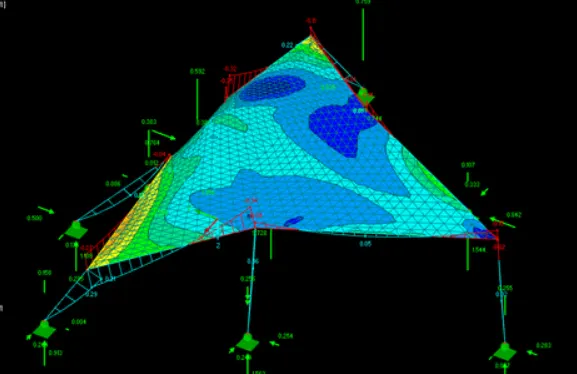
Project 2
Question: Model of a membrane roof with cables. The modeling, form-finding and create the cutting patterns to the structure.
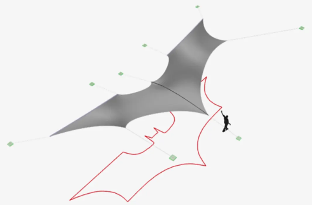
AIM: To perform Form-Finding Analysis on Membrane Roof with cables using RFEM software.
PROCEDURE:-
- The very first step in order to perform the form-finding analysis on membrane roof with cables using the software, first open the RFEM software and then select new file using the option named as the New Model just click on that option or [Ctrl+N] just as shown in the below given image:

- After that there will be another dialogue box named as the New Model-General Data is appeared just as shown in the below given image:
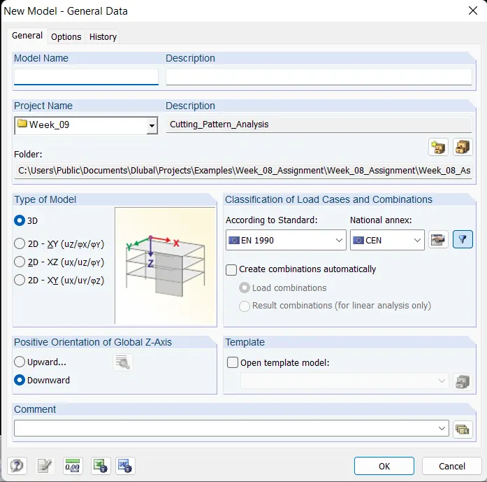
- Next fill out the details in that dialouge box about the model just as shown in the below given image:
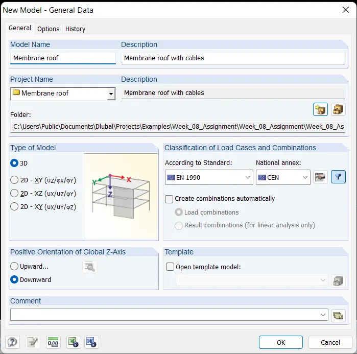
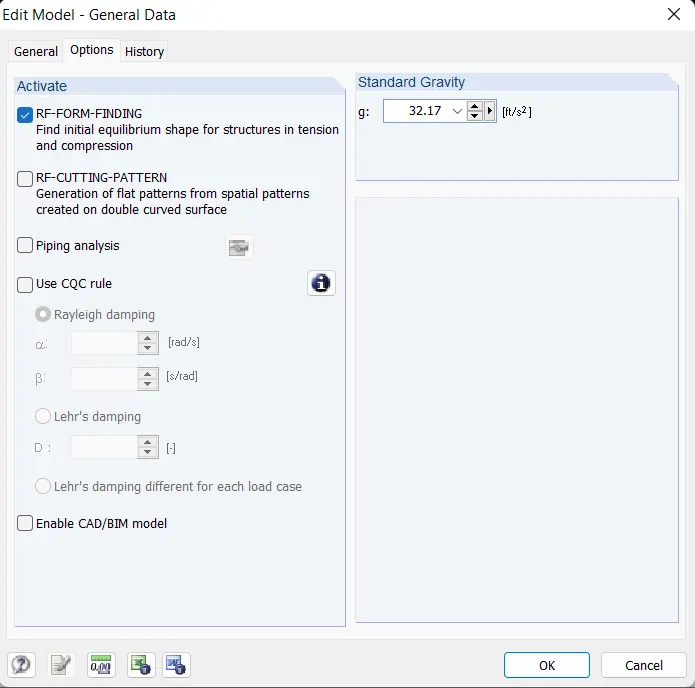
- Also in general data click on option and in that select RE-FORM-FINDING option just as shown in the below given image:
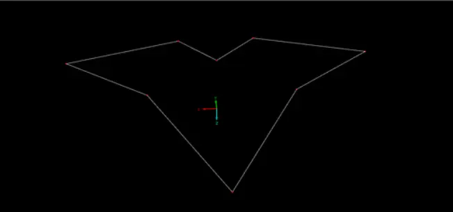
- After that draw the stucture using the line tools just as shown in the below given image:
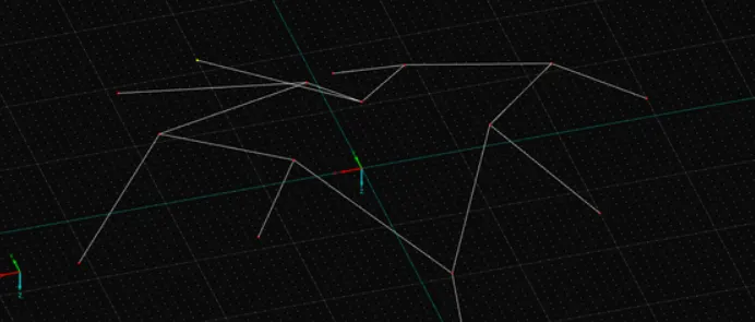
- And then next we will be drawing the supports using the line command in the ribbon tab just as shown in the below given image:
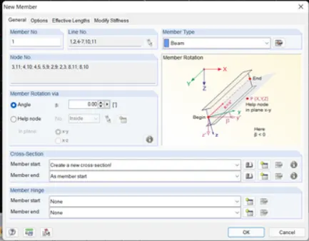
- Next select all the lines and double click on them then there will be another dialouge box named as the New Member and in that dialouge box assign cable member to them just as shown below in the below given image:
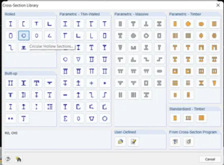
- Next there will be another dialouge box named as the Cross-section Library and in that dialouge b ox there will be an option named as the Cross Hollow Sections... just click on that option just as shown in the below given image:
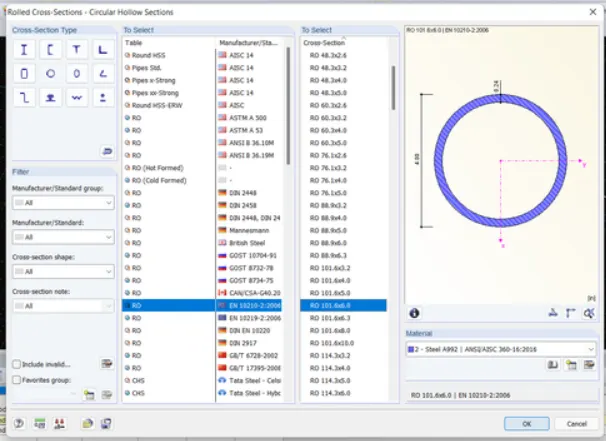
- And then next there will be another dialouge box named as the Rolled Cross-Sections-Circular Hollow Sections and in that dialoluge box select the materials just as shown in the below given image:
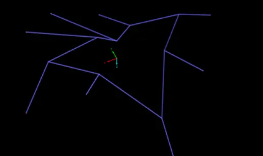
- Now we can see the materials has been assigned in the structure just as shown in the below given image:
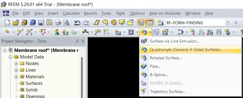
- Then next go to surface option in the ribbon tab select that option then there will be a drop-down list and in that list there will be another option named as the Quadrangle [General 4 sided Surfaces..] just click on that option just as shown in the below given image:
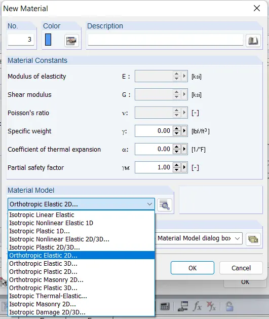
- Then there will be another dialouge box named as the New Material and in that dialouge box named as the Material Model just click on that option then there will be another drop down list and in that list there will be an option named as the Orthotropic Elastic 2D... click on that option just as shown in the below given image:
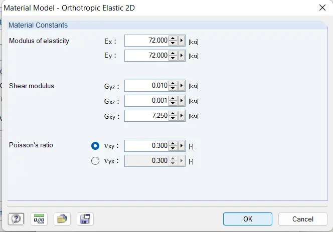
- Then there will be a new dialouge box named as the Material Model - Orthotropic Elastic 2D and in that dialouge box fill out the details just as shown in the below give image:
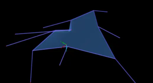
- Below is the image after assigning the materials:
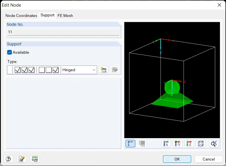
- After that select all the nodes and double click on them then a new dialogue box will appear named as the Edit Node and in that select support option and give supports to the nodes as Hinged just as shown in the below given image:
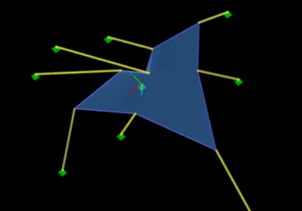
- Below is the image after assigning the supports to the nodes just as shown in the below given image:
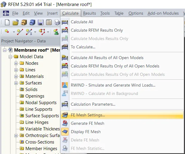
- Next there will be another option named as the Calculate just click on that tab then there will be a drop-down list and in that list there will be an option named as the FE Mesh Settings... just click on that option as we can see in the below given image:
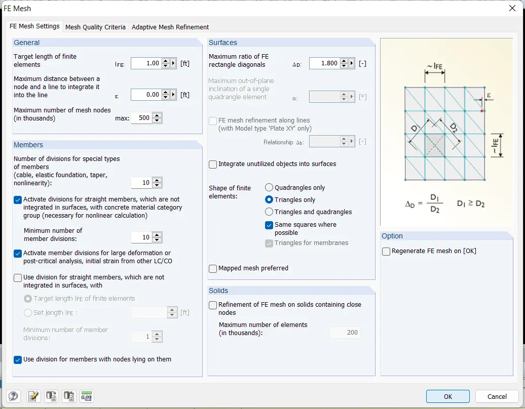
- Next there will be another dialouge box named as the FE Mesh and in that dialouge box fill out the all necessary details just as shown in the below given image:
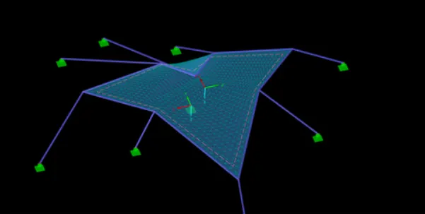
- Below is the image after applying the mesh properties:
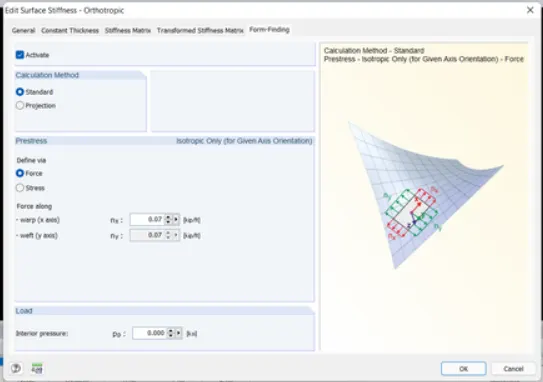
- After that click double click on surface of the structure then there will be a new dialogue box named as the Edit Surface Stiffeness - Orthotropic and in that dialouge box there will be an option named as the Form-Finding just click on that option and in that form-finding select warp as 0.10 and weft as 0.10 just as shown in the below given image:
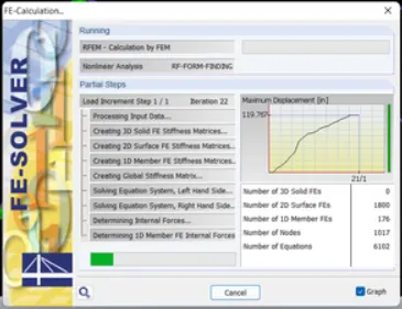
- Next select the form-finding option and start analysis for RE-FORM-FINDING as shown in the below given image:
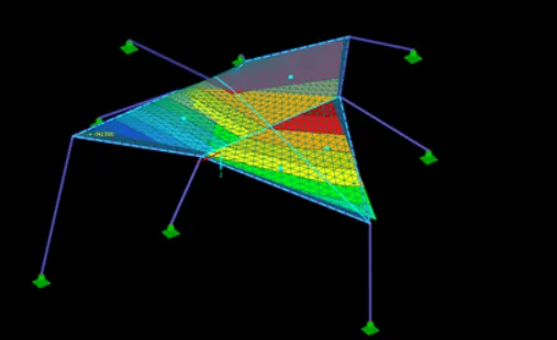
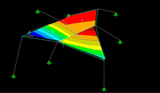
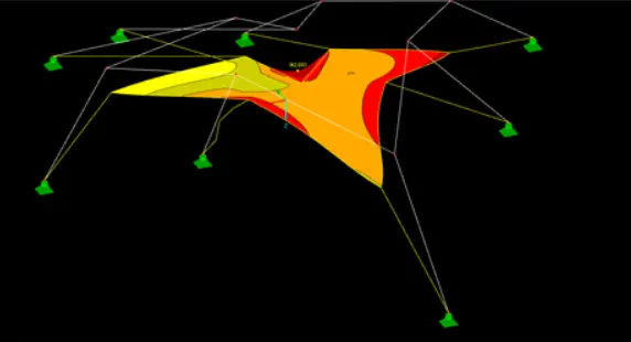
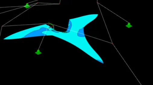
- After the RE-FORM-FINDING analysis the analysis results are shown in the below given images:
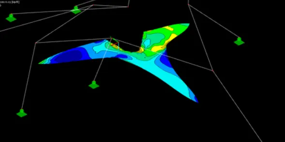
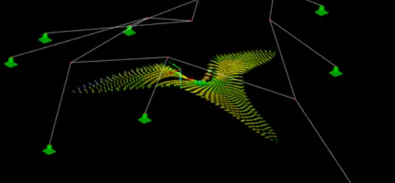
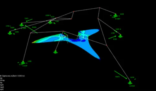
- Next we will be creating the different load cases just as shown in the below given image:

- Below is the image after creating the load cases as shown in the below given image:
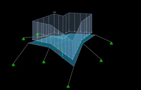
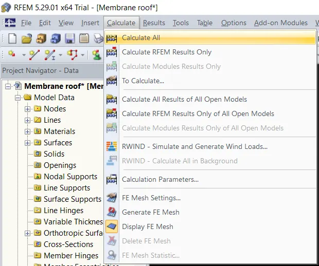
- Next we will be calculating the results and in order to do that there will be an option named as the Calculate just click on that option then there will be another drop-down list and in that list there will be another option named as the Calculate All just click on that option just as shown in the below given image:
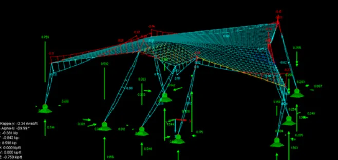
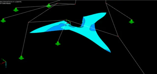
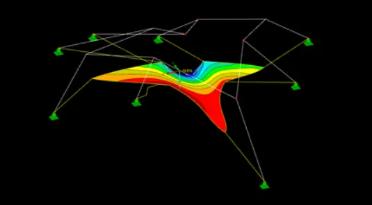
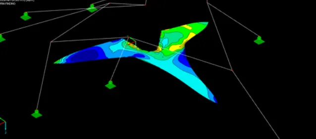
- The deformed shapes with internal stresses and forces are shown in the below given image:
- Next we will be performing the Cutting-pattern Analysis on Membrane Roof with cables using RFEM software.
- First open the RFEM software and select new file and a new dialogue box is appeared as shown in the below given image:
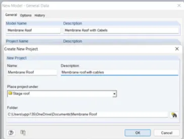
- And in that dialouge box give the name and discreption about the model and in add-on option select RE-CUTTING-PATTERN and click ok as shown in the below given image:
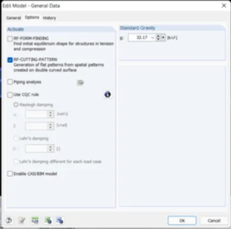
- After that select node option and create nodes as shown in the below given image:
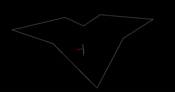
- And then next we will be drawing the supports using the line command in the ribbon tab just as shown in the below given image:
- Next select all the lines and double click on them then there will be another dialouge box named as the New Member and in that dialouge box assign cable member to them just as shown below in the below given image:
- Next there will be another dialouge box named as the Cross-section Library and in that dialouge b ox there will be an option named as the Cross Hollow Sections... just click on that option just as shown in the below given image:
- And then next there will be another dialouge box named as the Rolled Cross-Sections-Circular Hollow Sections and in that dialoluge box select the materials just as shown in the below given image:
- Now we can see the materials has been assigned in the structure just as shown in the below given image:
- Then next go to surface option in the ribbon tab select that option then there will be a drop-down list and in that list there will be another option named as the Quadrangle [General 4 sided Surfaces..] just click on that option just as shown in the below given image:
- Then there will be another dialouge box named as the New Material and in that dialouge box named as the Material Model just click on that option then there will be another drop down list and in that list there will be an option named as the Orthotropic Elastic 2D... click on that option just as shown in the below given image:
- Then there will be a new dialouge box named as the Material Model - Orthotropic Elastic 2D and in that dialouge box fill out the details just as shown in the below give image:
- Below is the image after assigning the materials:
- After that select all the nodes and double click on them then a new dialogue box will appear named as the Edit Node and in that select support option and give supports to the nodes as Hinged just as shown in the below given image:
- Below is the image after assigning the supports to the nodes just as shown in the below given image:
- Next there will be another option named as the Calculate just click on that tab then there will be a drop-down list and in that list there will be an option named as the FE Mesh Settings... just click on that option as we can see in the below given image:
- Next there will be another dialouge box named as the FE Mesh and in that dialouge box fill out the all necessary details just as shown in the below given image:
- Below is the image after applying the mesh properties:
- Next we have to select line option then right click on it then there will be a drop-down list and in that list there will be an option named as the New line click on that option then there will be another drop-down list and in that list there will be an option named as the Cut via Sections just click on that option just as shown in the below given image:
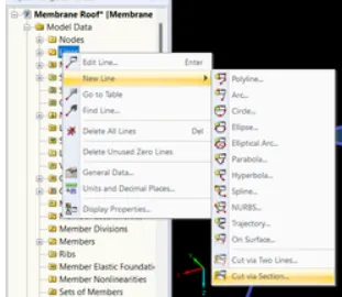
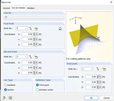
- Next there will be another dialouge box named as the New Line and in that dialouge box there will be another option named as the Cut via Sections click on that option and fill out the details just as shown in the below given image:
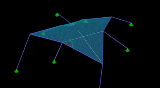
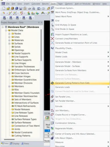
- Next go to tools option click on that option then there will be a drop-down list and in that list there will be another option named as the Generate Cutting Patterns from Cells just as shown in the below given image:
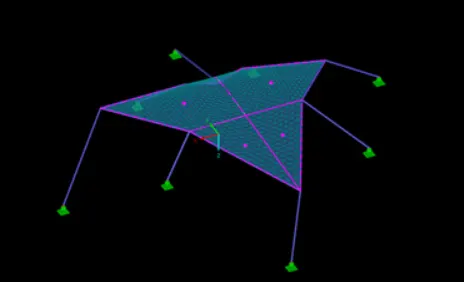
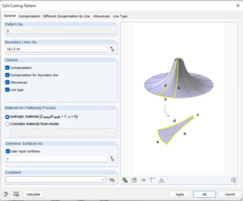
- After completing the analysis double click on cutting pattern surface then a new dialogue box is opened as shown in the below given image:
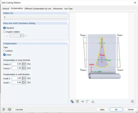
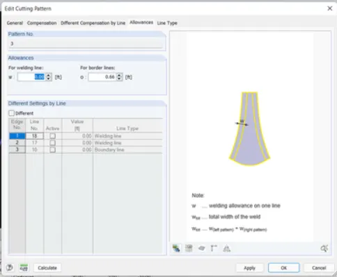
- In that click on compensation and Allowance and in compensation give wrap value as 1 and weft value as 3 and allowace as 0.33ft as shown in the below given image:
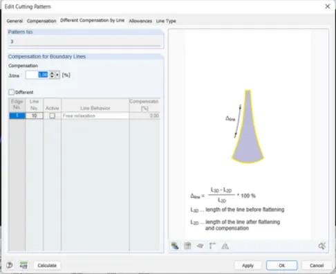
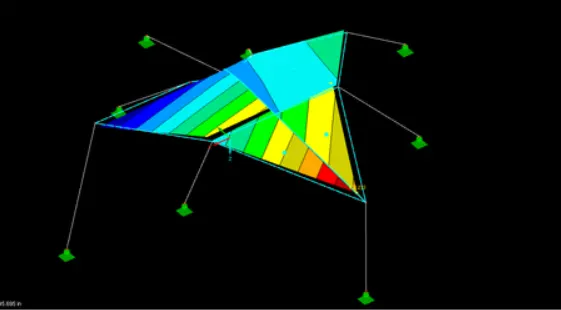
- After that select calculate option and in that select to calculate then the analysis is started. Then the RE-CUTTING-ANALYSIS results are shown in the below given image: