Project 2
AIM:
Route the Wiring harness on Given car body and prepare flatten view drawing in CATIA V5. Application of all Packaging rules, Industry best practices studied in this course shall be demonstrated in design. Apply Protection coverings as required.
Available connector 3D data can be used, or you can download the connectors from www.te.com
Prepare & submit all necessary reports like clearance, Clipping/Clamping selection, Harness fixing requirements, Harness continuity, Assumptions if any along with CATIA 3D data
Wiring harness:
Wire harnesses are a mixture of wires that are bundled together to form a wire harness. Wire harnesses range in complexity from a few individual wires going point to point to hundreds of individual wires, multi-conductor cables and welded wires all forming a complex wire harness used to transmit power and all types of data. Wire harness designs are highly customizable, as harnesses are typically designed to suit specific applications. They may need to be concealed behind walls, fit within electrical boxes, or conform to other space constraints. Precise measurements of the environment, power demand, and lengths must be taken during design to prevent costly mistakes and ensure proper safety and functionality of the final product.
A wiring harness routing structure includes a wiring harness routing member configured to be attached to a vehicle body and a protector that accommodates and holds a wiring harness. The protector has a recess shape in which the protector is opened in one direction in a sectional view. At least one of the wiring harness routing members and the protector includes a fixing mechanism that fixes the protector to the wiring harness routing member. The protector and the wiring harness routing member are configured to be integrated via the fixing mechanism.
Wiring of car back door:
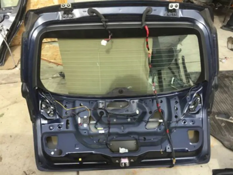
Coming to the wiring harness of the car back door, there have to need wiring harness routing to the different electrical equipment system to performed their functionality.
The back door is provides the courage area to the passengers to keep materials and carrying with them. Not only that in back door consists other type of functions like mounting of wind shield glass, tail lamp, indicators, fog lamp and wiper motor etc.
For all these systems needs the power and electrical signals, data communication between equipment to equipment, so that reason in back door also we are routing the wiring like wiring for tail lamps, indicators, wiper motor, sound system and fog lamps.
DESIGN METHODOLOGY
The design methodology or design approach which is used for this challenge is explained or given in the below flow chart,
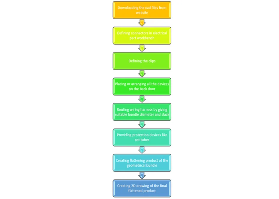
Design methodology:
In this project we are studying and understanding the wiring harness for the back door of a car with suitable design procedure in Catia v5.
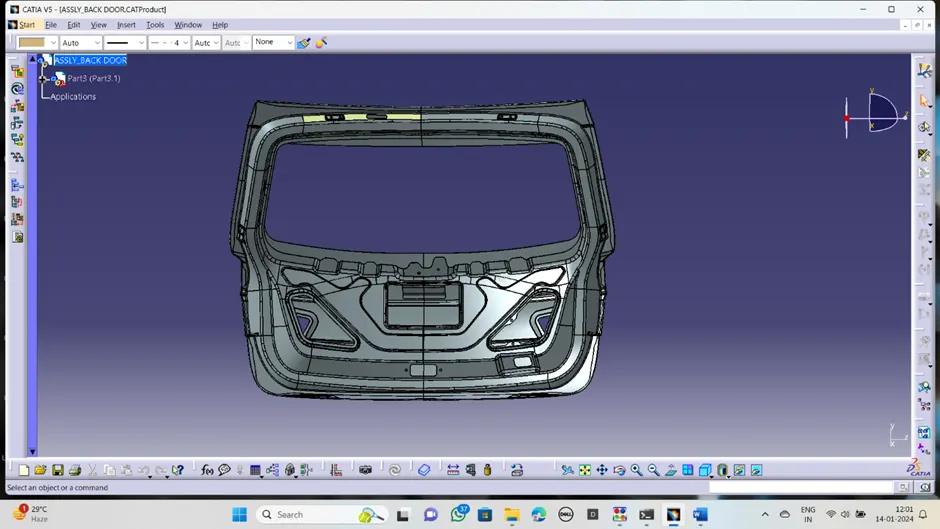
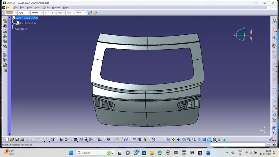
· First open the cad file of the back door assembly given reference link. Identify and mark the different connectors and clamp mounting locations based on requirements for routing.
· Then decide the type of connectors and mounting clamps required to the routing properly for the back door
Define the connectors as a electrical components:
To routing there need of different connectors to connect the network and requires some clips and clamps to hold the routing bundles across the back door, to keep safely and provides aesthetic appearance.
· First download the necessary connectors cad file from the available source like telecon connectors and arrayments etc.
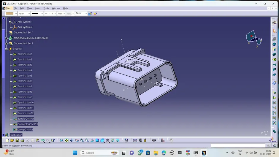
· Identify the connector connection face and bundle entry face, create the geometrical properties like point, select the proper edges on connector face and create the point exactly centre of face. create the axis system with respect to that point in connector meeting side.
· During axis creation keep the y axis in the meeting direction of other connector and x-axis should be in locking direction of the connector.
· Now go to the electrical part bench, define the component as a electrical connector by click on connector definition.in that select the number of terminals present to connector.
· Create the bundle connection point in the bundle entry side by bundle connection definition. Select the face and point.
· Create the connector connection point in the connector meeting side by selecting the proper point, coincidence and contact surface or face.
· Now the connector became electrical component, it is ready to use in wiring harness.
Inter connection connector
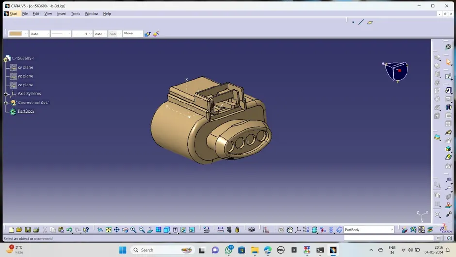
C-1563689
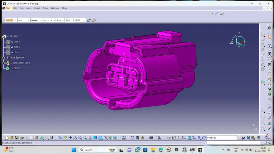
C-173090
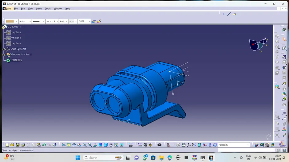
C-282080
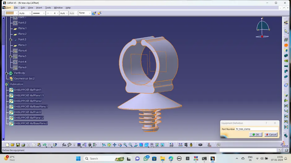
Define the firr clip:
This is the one type of clip used in the automotive wring harness to hold the wire bundle together and safely in defined direction. Here this clamp also need to define as electrical part. By below procedure,
· Study the firr clip and understand how the bundle passed through it and identify the entry and exit base.
· Create points either side of the clamp and make a plane through parallel to the point ,one is entry plane and other is exit plane, also create a base plane to the bottom surface.
· Along these parameters define the clamp as electrically by selecting support option and select appropriate planes in definition.
· Now the firr clamp is defined electrically and as below:
Wiring harness mounting strategy and selection parameters
Mounting strategy and selection parameters for components, terminals, wire, protection devices, should be strictly followed clearance management while routing
Some of the Harness branching rules are,
Branch length should be greater than 50mm
Minimum distance between clamp and nearby branching point should be 25mm.
Minimum distance between two breakouts should be 25mm.
Back door routing assembly:
In the assembly first have to create the new product file named it as back door assembly context and save it into separate file.
Under the main assembly create the another two product files and named it into, one has back door assembly and other is back door assembly geometrical bundle.
· Open the back door assembly and paste into context assembly file
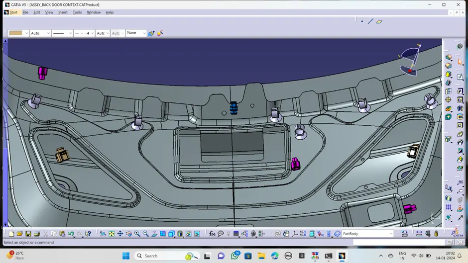
· Open the assembly geometrical bundle product in new window and add all necessary connector and clips& clamps
· As initial marking and planning of connectors where ever need, place the connectors in that locations ;
v Place the connectors one is inter connector is located at top of the back door
v Two connecters are placed for two tail laps and indicators
v One connector foe wiper motor connection
v One connector for number plate visibility purpose and sound system
v For fog lamp at the top of the back door.
· After arranging all connectors in it places, now go to the clamps. The clamps should be placed in between the connectors where the gap is more. Take the firr clamp and positioned it serially at every 200mm distance from starting connector to the end connector.
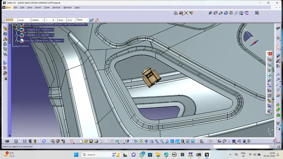
Tail lamp connector:
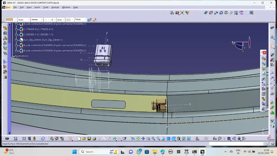
Interconnection connector:
Wiper motor connector:
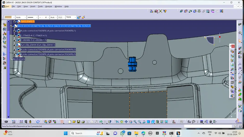
Firr clamps:
· Now go to the wiring harness assembly start routing process.
· Define the back door assembly geometrical bundle fine into geometrical by clicking on it.
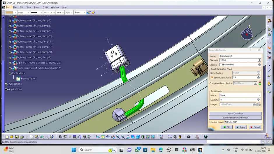
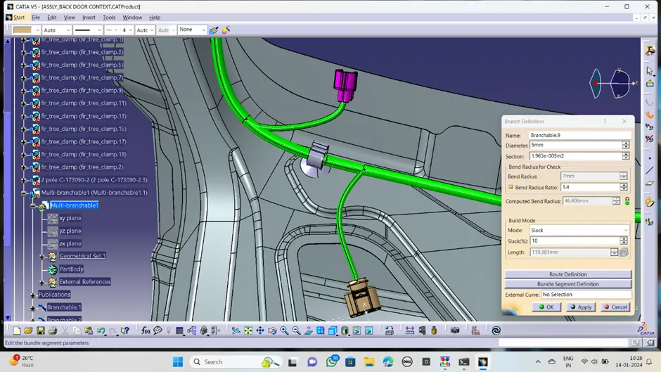
· Start the routing by clicking on the multibranchable, where we can see a dialogue box in which have to enter the bundle diameter ,then go to the route definition, where select the connector and near by clamp. Then we will get the bundle between the connector and clamp.
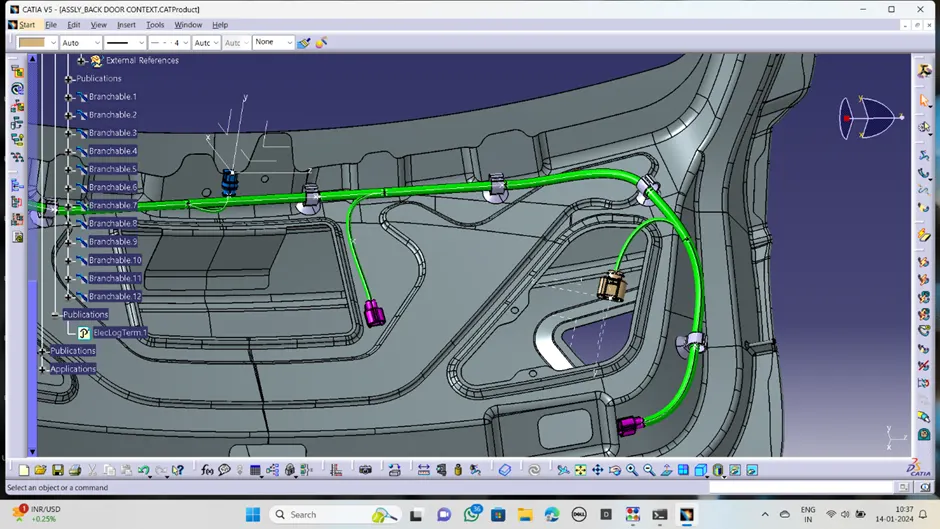
· Same way apply the branch definition and create the bundle routing from staring to the end.
· For tail lamp and other some connectors have to divide from the main trunk, so that we have to create the branch point on the main trunk and go to the branch definition and again route the bundle to other connectors as well.
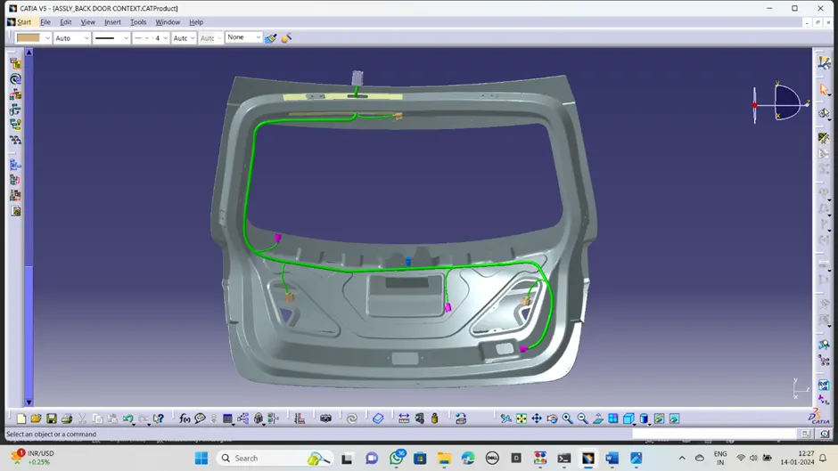
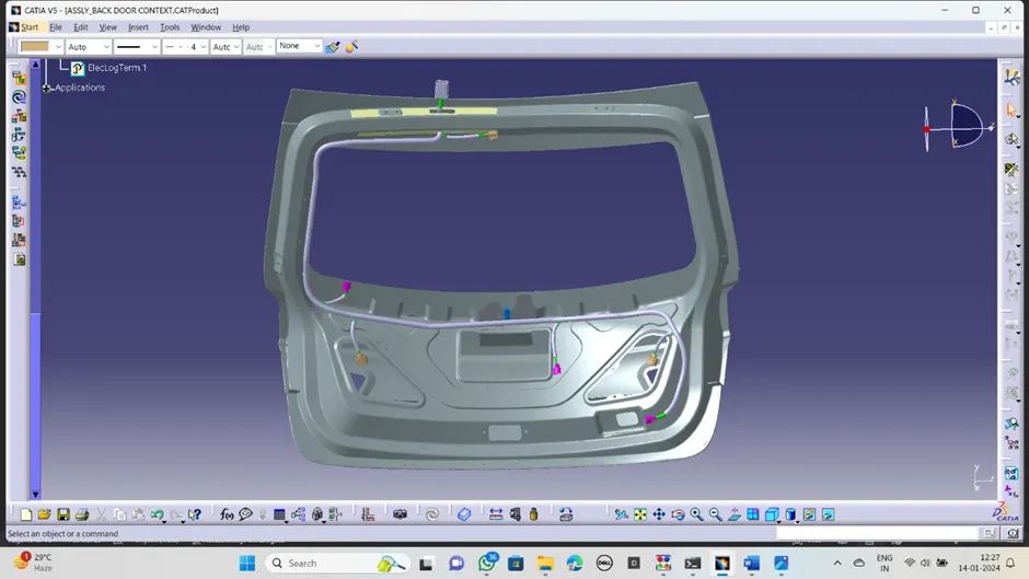
· In this way entire back door routed the harness bundles for all systems.
Check the connectivity:
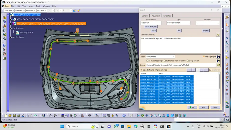
Under the edit command select the search icon (binocular symbol) a pop-up window will appear to select the advanced option and arrange the options available by selecting, workbench as electrical, type as bundle segment and attribute as fully connected.
A pop-up window will appear, while selecting it as false and selecting the search button it will show all the discontinued bundles in the assembly. If we select it as true, it will show a fully interconnected bundle throughout the assembly.
Bundle warnings are mainly due to the inappropriate bend radius given to the bundle this can be solved by adjusting the position of connectors, adjusting the bundle break point for sub-branches, reversing the tangency of the bundle, adding extra slag, etc.
It is recommended to maintain the tentative bend radius always less than that of the computed bend radius of bundles. Checked for the bundle continuity and bundle warnings in the geometrical bundle assembly when the query was set as True
Protective covering;
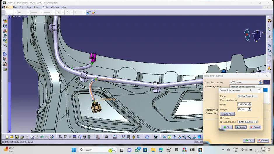
Protective covering is the main important thing in the wiring harness because, the bundle will face many physical damages issue and environmental conditions.so if we not provide proper protections, it will damage easily and fastly.so that we provides the some protective covers to keep it safely.
In automotive field we mostly use the corrugated tubes.s
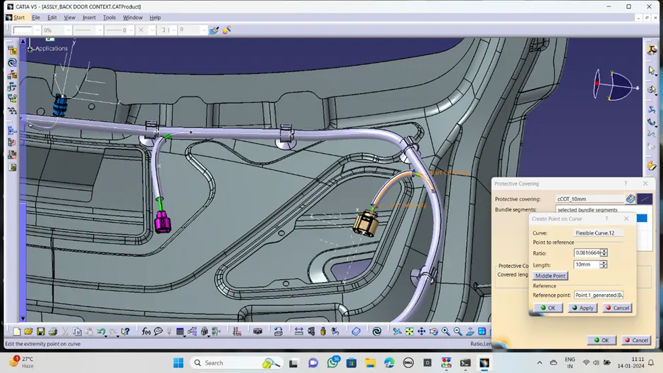
· Go to the protective covering command and select the proper cot tube from the catalogue we have and select the bundle where we want to apply click on ok then there, we get the covering around the bundle.
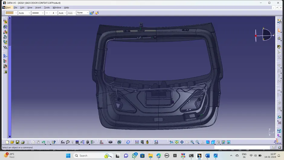
· After protective covering it look as below;
Wiring harness flattening of back door harness:
After completion of the all routing process now have to go to routing harness flattening.in this section we converted the geometrical bundle harness into flatten harness like 2D file.
For that ,we go into the harness flatten work bench and start it.
· Create the new product file and name it as back door assembly harness flatten then save into save folder.
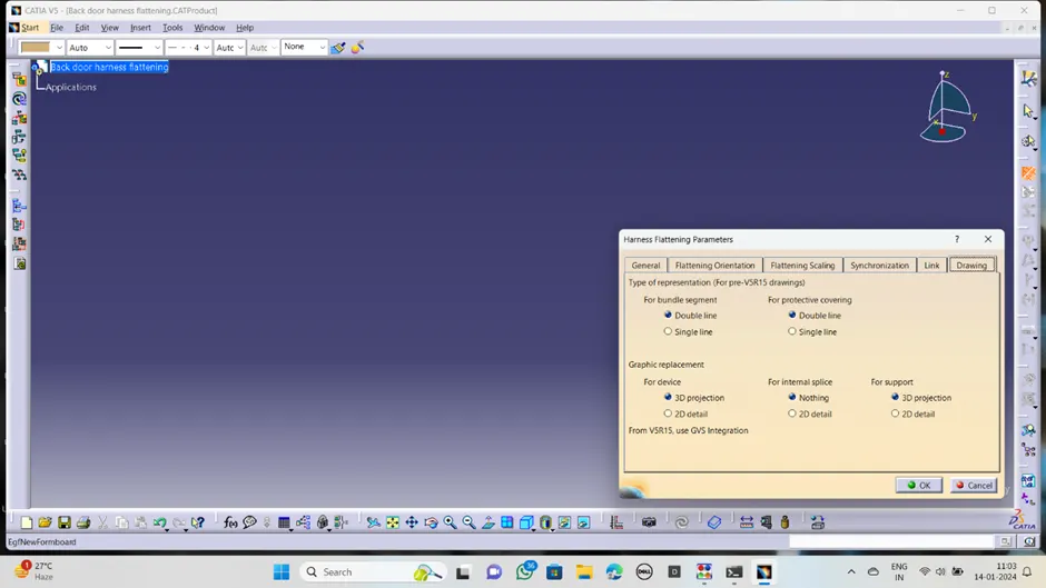
· Define the flatten parameters by click on flatten definition and select and enable the required parameters related to our design.
· Go to the extract command and click on geometrical bundle from context assembly and click ok.
· Then the geometrical bundle will appear in flatten product, then click on the flatten option available in the work bench.
· Now the geometrical bundle will convert into flatten bundle.
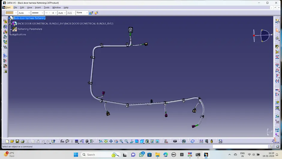
Flatten harness as below;
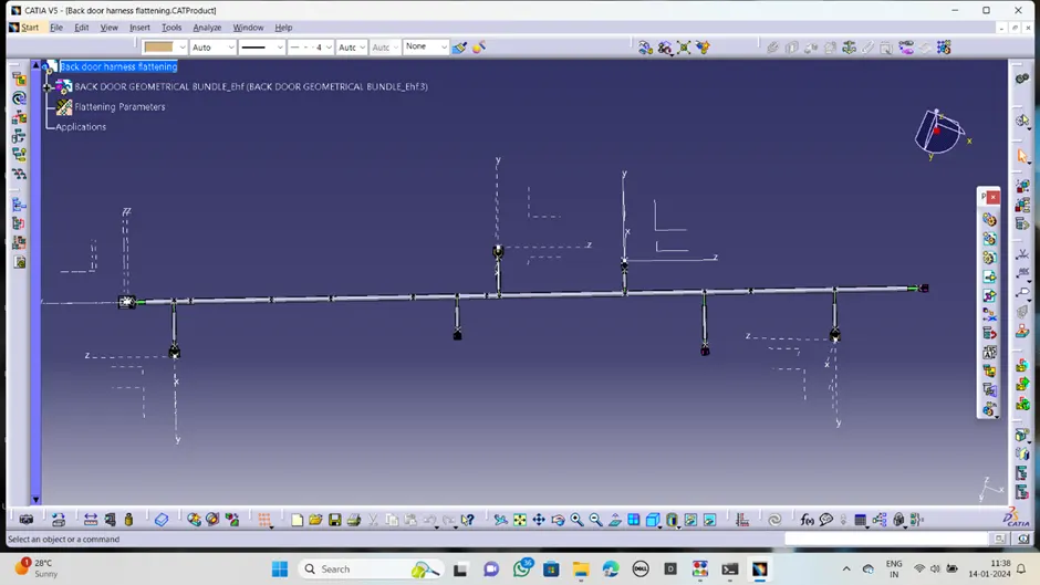
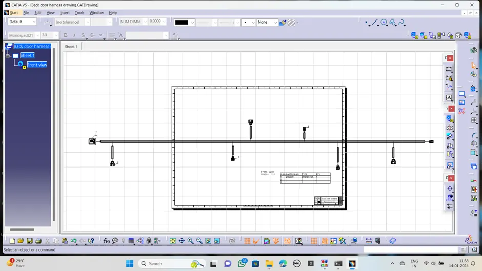
Flatten harness converting into drawing:
Now we're creating a new drawing file and defining all of the required drawing parameters. The front view of the Backdoor wire Harness Flattening Product file must be inserted into the Drawing file. It should be noted that the 3D wireframe is always ON in the 'Dress up settings. If this option is not enabled, the bundle segments will not be visible in the drawing view. the Backdoor wire Harness Flattens view's final Drawing view.
Before creating flatten view, first we have to define flattening parameters. Make sure that selecting ‘Single line’ for bundle segment and Double line for protective covering
Back door harness assembly:
Conclusion:
in this project we defined all connectors,clips as electrical equipments and arranged on the back door of car.then routing the wiring harness as per our requirements,provided the protective covers over harness bundles.
finally done the flatten harness for the back door harness assembly and made the 2D drafting of the flatten harness.