Project 2
Battery resistance =2milliohm
Consider the battery resistance is 0.5mohm
Entropic factor is =2
Heat generated =joules heat+entropy heat
Joules heat
When the current flowing through a resistance there is a heat dissipated in the resistance this heat dissiption is called heating
Joules heating is alsoknown as ohmic heating
Power p=VI
From ohm's law
V=IR
power
P=V*I
p=IR*I
P=I2R
Heat
H=∫p.dt
H=∫0tI*IRt
H=I2Rt
Joule heat
H=I2Rt
P=Power
V=voltage
I=current
R=resistance
H=heat
T=time
Entropy heat
The heat generation due to entropy change inside a battery occurs when electro chemical reaction are performed. the entropy heat is reversible heat resulting from change in open circuit voltage with respect to temperature at two electrodes.
batterry resistance = 0.5m ohm = 0.0005ohm.
a) Maximum heat generated = maximum joule heat + 2(maximum joule heat)
Imax = -0.896 A
tmax = 1.7 sec
Rint = 0.0005 ohm
maximum joule heat = (Imax)^2 * R * tmax
maximum joule heat = (-0.896)^2 * 0.0005 * 1.7 = 0.000682393J
Maximum heat generated = maximum joule heat + 2(maximum joule heat)
Maximum heat generated = 0.000682393J+2(0.000682393J)
=0.0020471808j
The SOC of the battery at 2 *104second of the battery operation
SOC = State of Charge is defines the how energy is usable for application
SOC = Q / Qmax
where,
Q = Available capacity
Qmax = Overall capacity
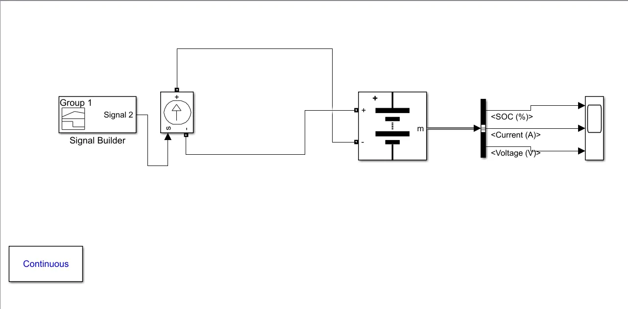
for the simulation model following blocks are used
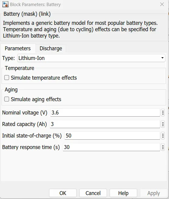
Generic Battery - Implements a generic battery model for most popular battery types. Temperature and aging (due to cycling) effects can be specified for Lithium-Ion battery type.
Controlled current source - Converts the Simulink input signal into an equivalent current source. The generated current is driven by the input signal of the block.You can initialize your circuit with a specific AC or DC current. If you want to start the simulation in steady-state, the block input must be connected to a signal starting as a sinusoidal or DC waveform corresponding to the initial values.
Bus Selector -This block accepts a bus as input which can be created from a Bus Creator, Bus Selector or a block that defines its output using a bus object. The left listbox shows the elements in the input bus. Use the Select button to select the output elements. The right listbox shows the selections. Use the Up, Down, or Remove button to reorder the selections. Check 'Output as virtual bus' to output a single bus.
Signal Builder Block -To use any type of signal till 208 stop time.
Scope- to Display the output graph
Powergui -Set simulation type, simulation parameters, and preferences
The SoC refers to the State of Charge of the battery, which is the capacity percent left in the battery which can be used. It a very improtent thing which teles about the battery status which helps in using the battery in a proper manner.
The SoC can be measued in different ways. Some of them are listed below
- Voltage Translation Method (VT)
- Coulamb counting method (CC)
- Combination of VT and CC
The VT and CC has its own advantages ad disadvantages so to get accurate value we have to use the Combination of VT and CC.
Voltage Translation Method (VT):
It is measued by Open Circut Voltge of the battery and compared it with the Data sheet of the battery and SoC is estimated. It cannot used while the battery is in operation.
Coulamb counting method (CC):
It is calculated by the formula
SoC = Total charge input / Max capacity of the battery
Total charge input = charge current * time (H)
Z(t) = Z(0) - 1/Cn ∫ Ni*i(t) dt with thw limits of 0 to t
where, Cn = Battery Nominal Capacity
Z(t) = State of charge
i(t) = Instantansous cell current
t = time
Ni = coulomb efficiency
Z(0) = initial state of charge
+ for discharging
- for charging
Due to Faid in the battery capacity over the time it shows error
Combination of VT and CC:To avoid the calculation of SoC both the Voltage Translation Method (VT) and Coulamb counting method (CC) are used combinedly.
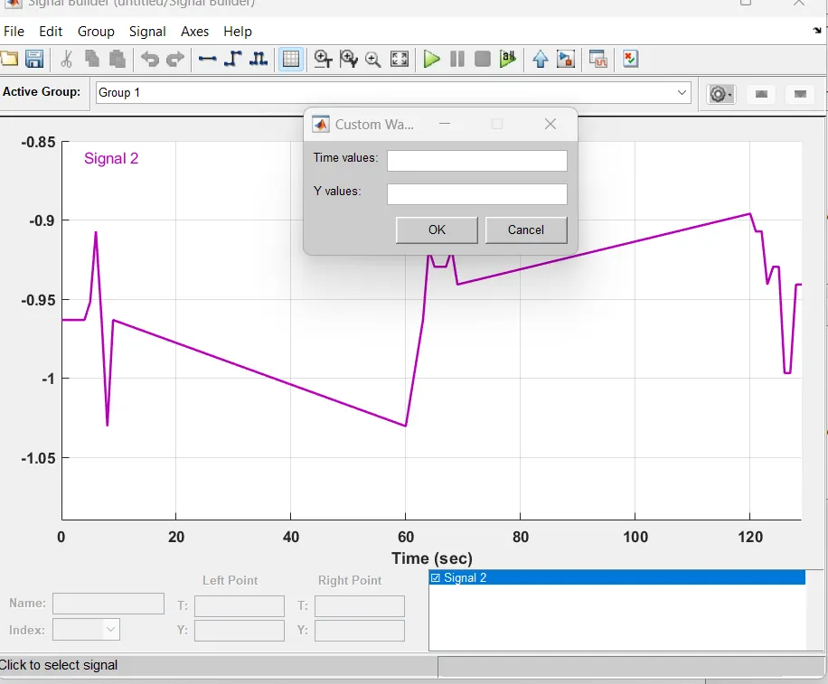
Input of the signal builder
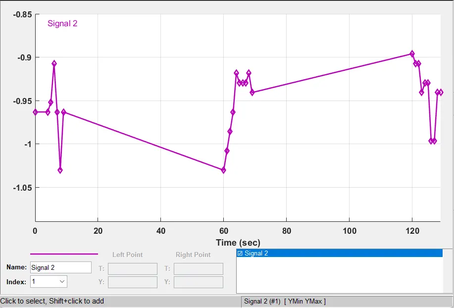
So i Time sec in Time value enter to this way : [4 5 6 7 8 9 60 61 62 63 64 65 66 67 68 69 120 121 122 123 124 125 126 127 128 129]
Y value is enter to Battery current with the help of [] ,Y value :[-0.9632 -0.952 -0.9072 -0.9632 -1.0304 -0.9632 -1.0304 -1.008 -0.9856 -0.9632 -0.9184 -0.9296 -0.9296 -0.9296 -0.9184 -0.9408 -0.896 -0.9072 -0.9072 -0.9408 -0.9296 -0.9296 -0.9968 -0.9968 -0.9408 -0.9408]
So build the new signal builder
Battery parameter
Below this drawing is for charging
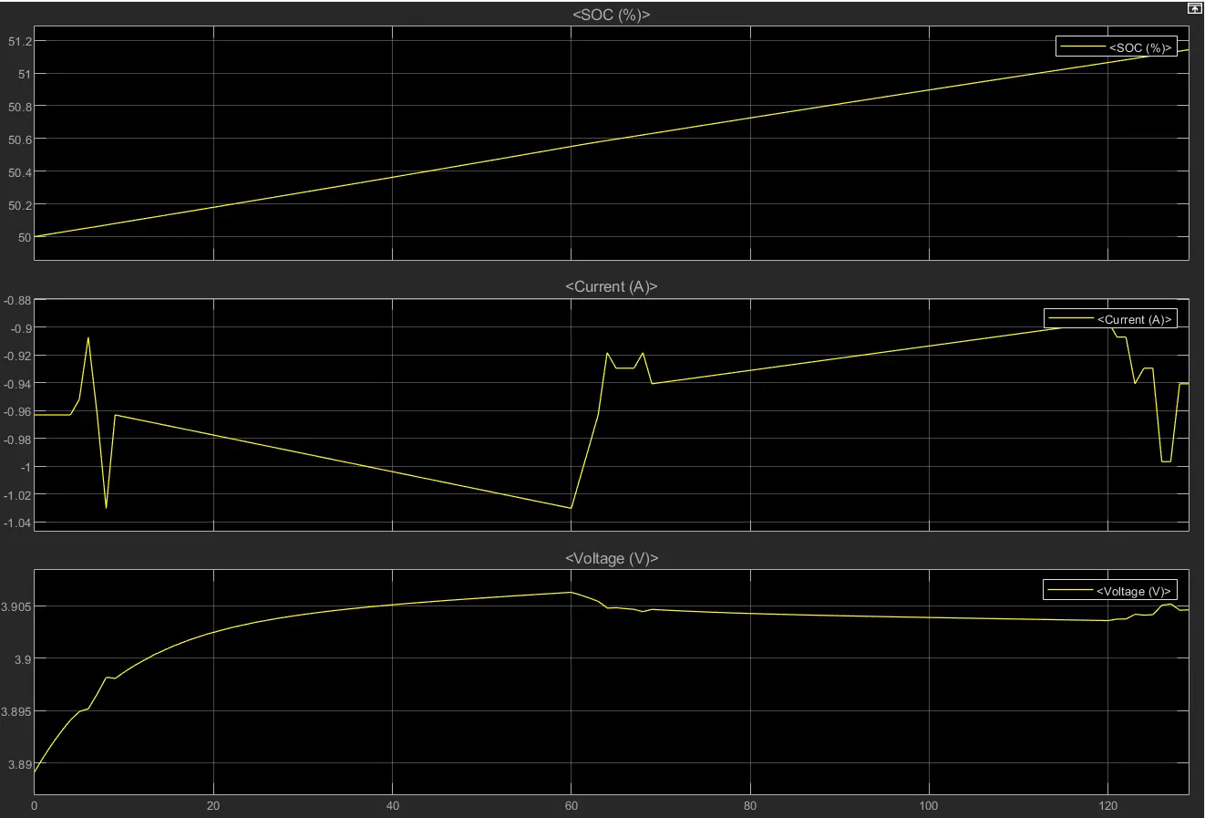
Result and Conclusion:
The max heat generation of the battery
The Max heat generated in which the current flowing in and out i.e., charge and discharge due to internal resistance and chemical reaction during charging and discharging of the battery the heat is generates of 0.0020471808j Jouls.