Project 2
AUTOMOTIVE WIRING HARNESS USING CATIA V5 – PROJECT II
Objective
The objective of the project is to route the wiring harness on given Backdoor of a car and prepare flatten view drawing in CATIA V5. All types of packaging rules have to be considered while routing the harness. Also, Industry best practices should be demonstrated in design. All the necessary details like clearance, clipping/clamping selection, harness fixing requirements, harness continuity should be provided in order to design wiring harness.
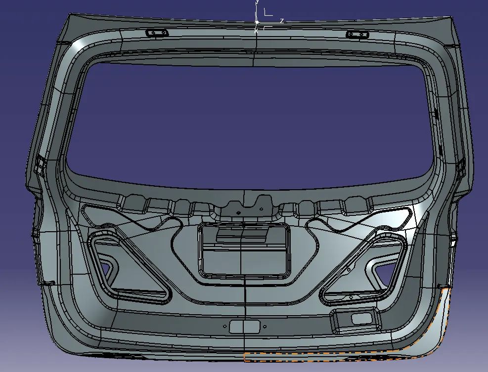
Assumptions-
The wiring harness packaging rules and the industry best practices that have to be followed to complete this project are as follows: -
1.When designing the wiring harness, ease of manufacture, installation, removal, and maintenance must be taken into account.
2.Avoid routing through tiny structural holes or apertures to reduce handling and chaffing during installation.
3.When assembling or servicing a harness, avoid routing and clipping in regions that are difficult to access or in the blind zone.
4. If more slack is required due to the environment or the harness bending requirement, give it. The slack number for this project is between 1 and 5%.
5. When designing the wiring harness in the CAD environment, it should be ensured that there are no instances of fouling. To prevent fouling, additional clips or clamps may be employed.
6.Protect the harness by avoiding routing it close to edges with sharp edges.
7.There should be enough mounting tools like clamps and clips available.
8.More than 50mm should be present on the branch.
9.A minimum of 25mm should be left between the clip and the branch point.
10.There should be at least 50mm between the two branch locations as a minimum.
11.The wire harness should be simple to install and remove.
12.To avoid paying extra for specialized mounting solutions, clips and clamps for the wiring harness should be widely accessible on the market.
COMPONENTS USED
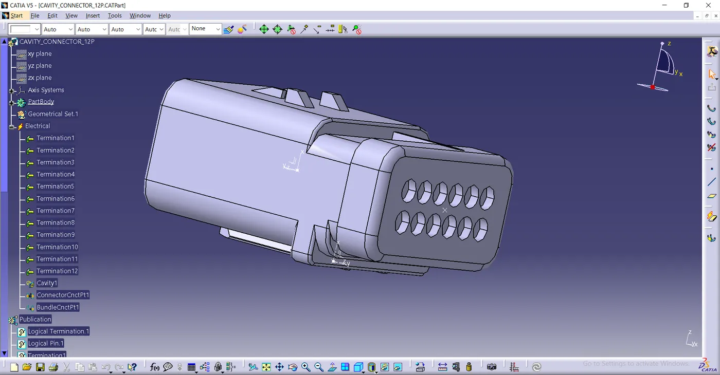
12POLE CONNECTOR – INTERCONNECTION CONNECTOR
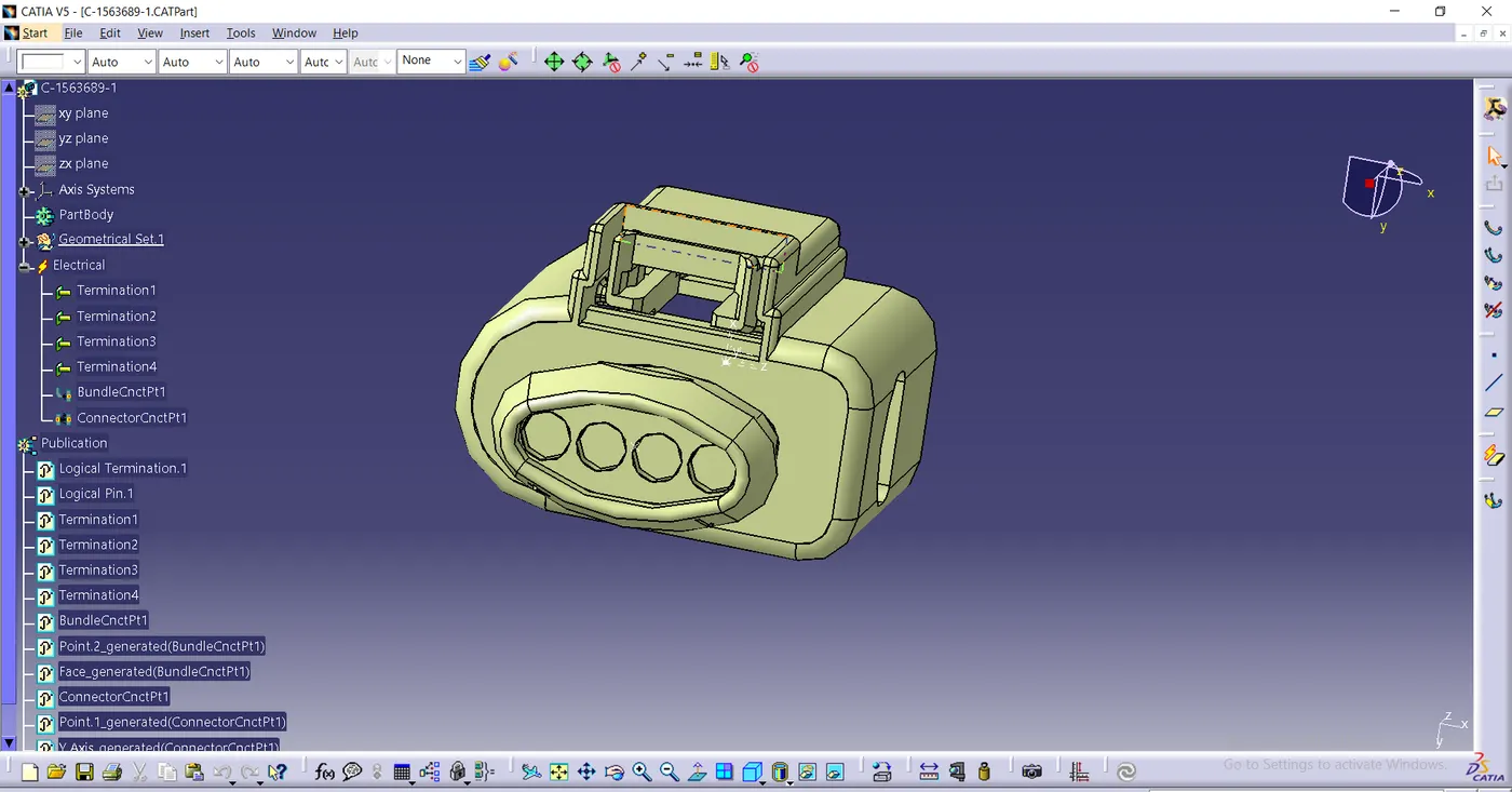
4 POLE CONNECTOR – TAIL LIGHT, WIPER CONNECTOR
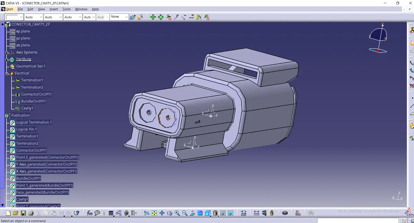
2 POLE CONNECTOR – NUMBER PLATE LIGHT CONNECTOR
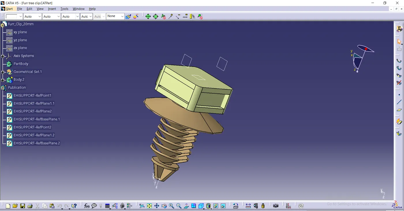
FURR TREE CLIP
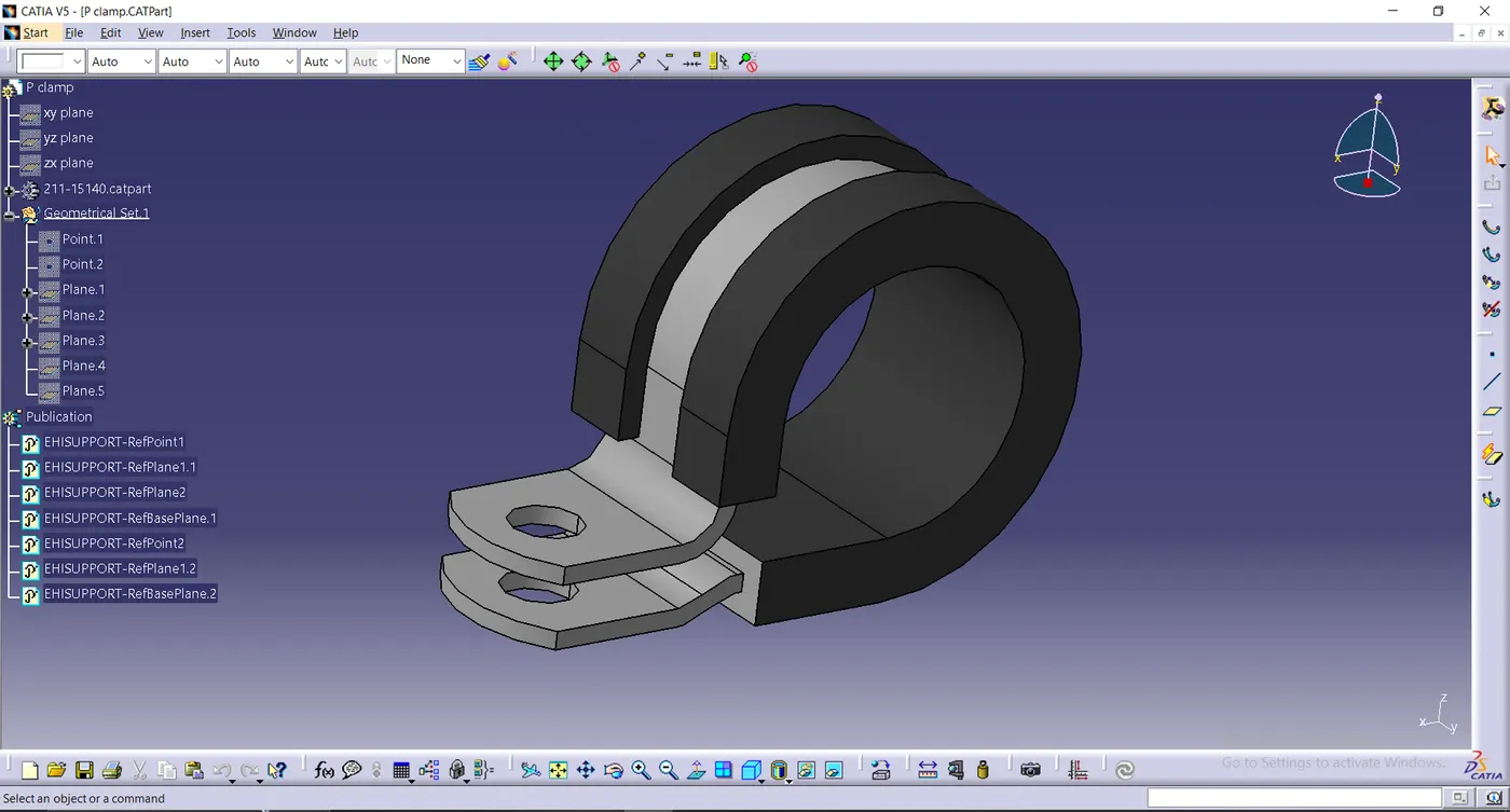
P_CLAMP
PROCEDURE TO ASSEMBLY PRODUCT: -
Step 1: Creating Context Assembly
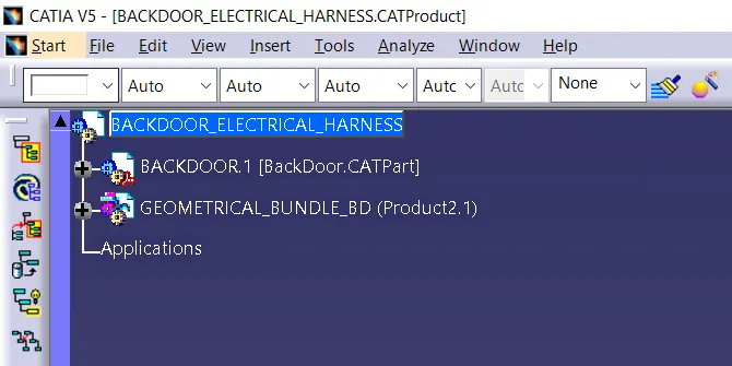
A Context Assembly for Backdoor Harness has created which will work as the main assembly as shown in above figure. A Context Assembly will contain Backdoor Assembly data and Backdoor Harness Geometrical Bundle Assembly. If any sheet metal bracket will require then they are added in the context assembly.
Step 2: To define Connectors electrically
We have to define all the connector that is 2 pole , 4 pole and 12 pole interconnection connector as an electrical part by define as connector connection point and bundle connection point. (ALL THE CONNECTORS IMAGES GIVEN ABOVE)
Also define the clip and channels that is needed as an electrical part.
Step 3: Adding connectors to the Backdoor
In this step, we are placing connectors for tail light, number plate light, wiper motor. So we will require total 6 connectors which have to be added in the Backdoor Geometrical Bundle Assembly. We have to use manipulation tools along with compass, snap and smart move features to locate all 6 connectors at their desired locations.
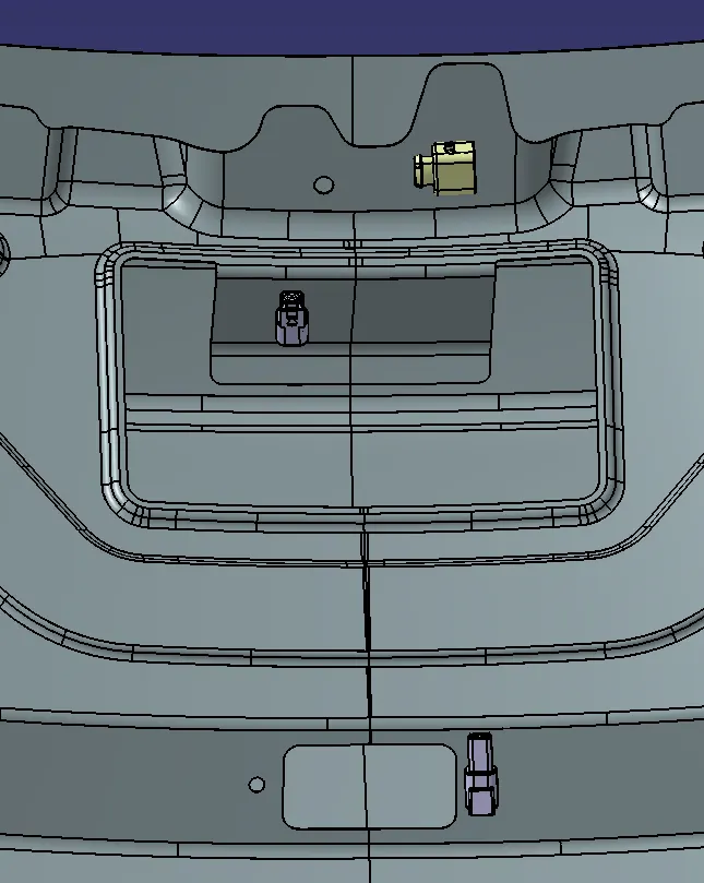
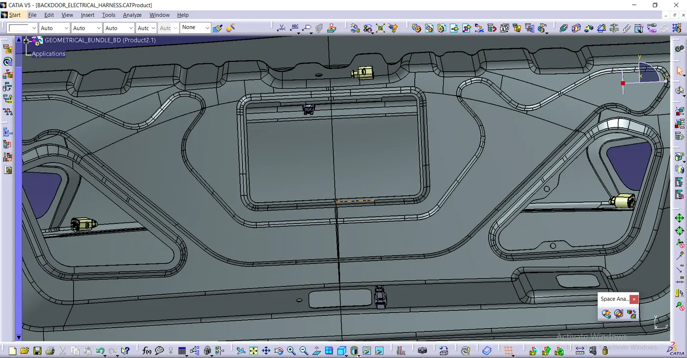
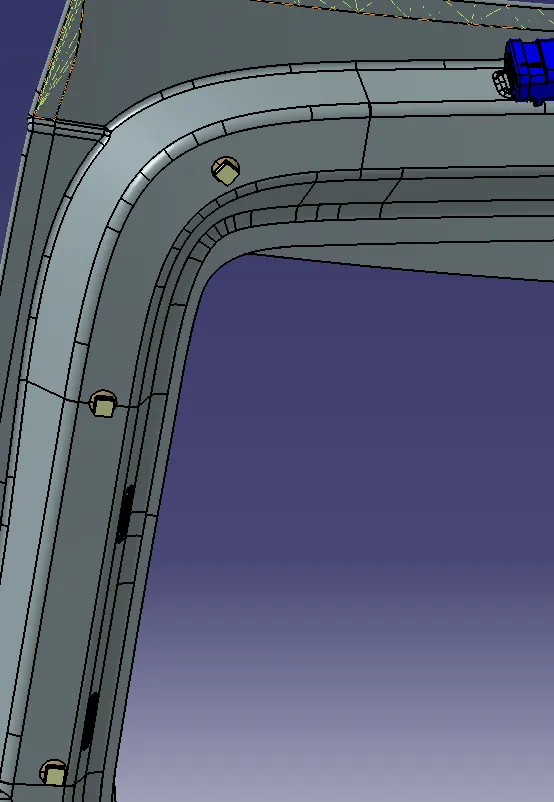
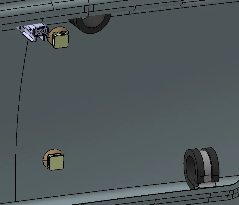
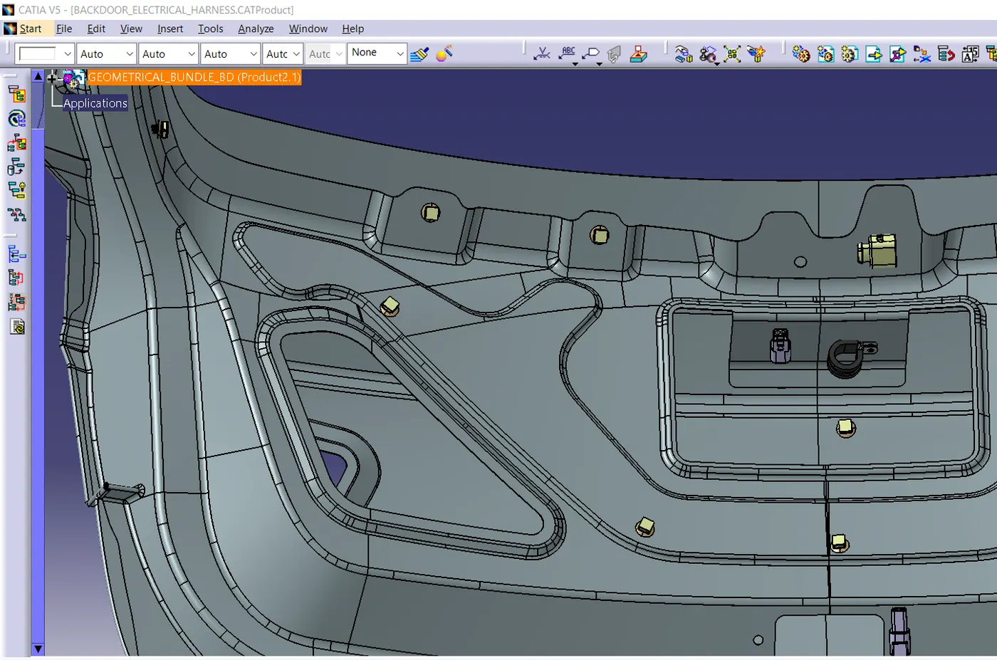
Step 4: Mounting the Clips & Clamps for wire harness
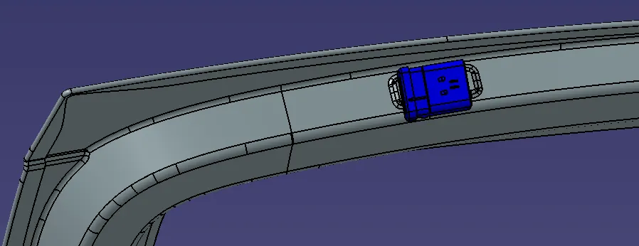
Interconnection connector is the major connector for wiring harness to the Backdoor. it needs to be firmly fixed to the bracket using clip for better rigidity.
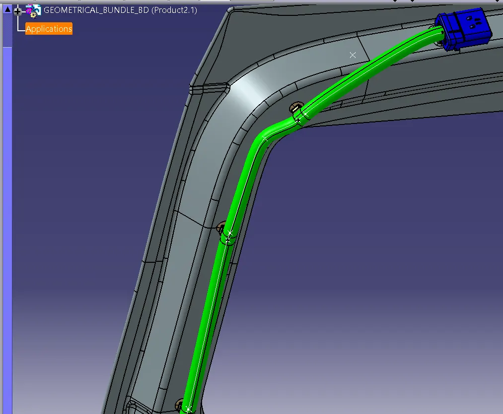
Step 5: Bundle routing from Interconnection connector to Clips
Wiring between Interconnection connection to the Clips are completed.
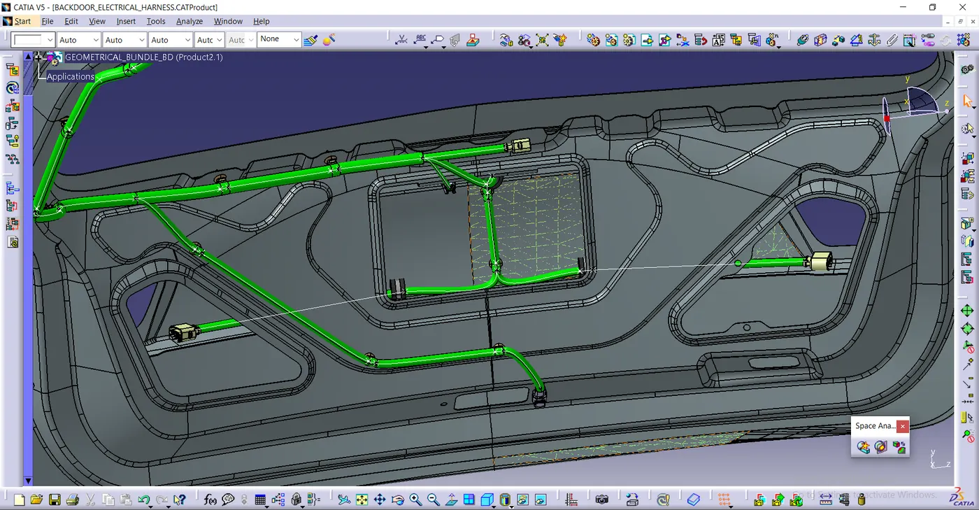
Step 6: Routing to all other connectors
Routing to other connectors such as connectors for tail light, number plate light, wiper motor with proper wiring parameters along with branch points to bundle segment.
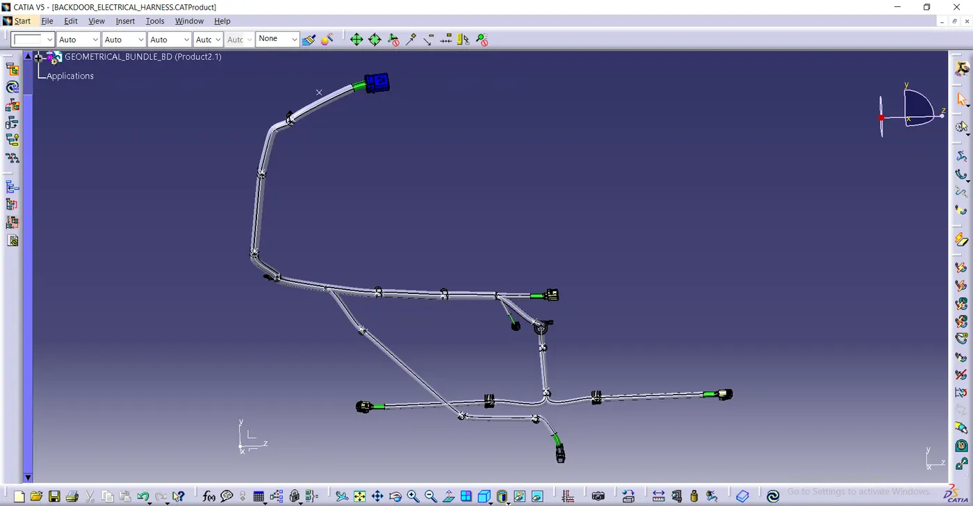
Step 7: Adding protective coverings to harness bundle
Default End extremity is taken as 30 mm to all the connectors and respective Corrugated tubes of diameter 5mm,10mm,15mm are used respectively. (Backdoor is hided for better visibility).
Step 8: Checking bundle continuity
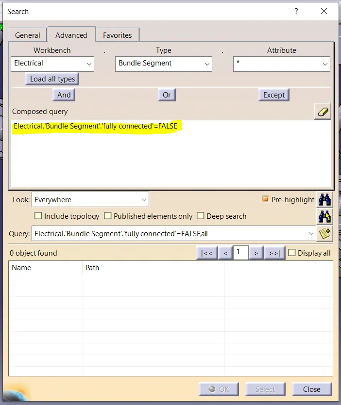
To check, go to Edit -> Search -> Advanced -> select workbench as 'ELECTRICAL' -> Type as 'BUNDLE SEGMENT' -> Attribute as 'FULLY CONNECTED' -> 'FALSE' -> click search icon. This will show the results of discontinued bundle segments from main wiring harness. When there is nil, our circuit is single piece harness and good to go.
Step 9: FLATENNING AS DRAWING
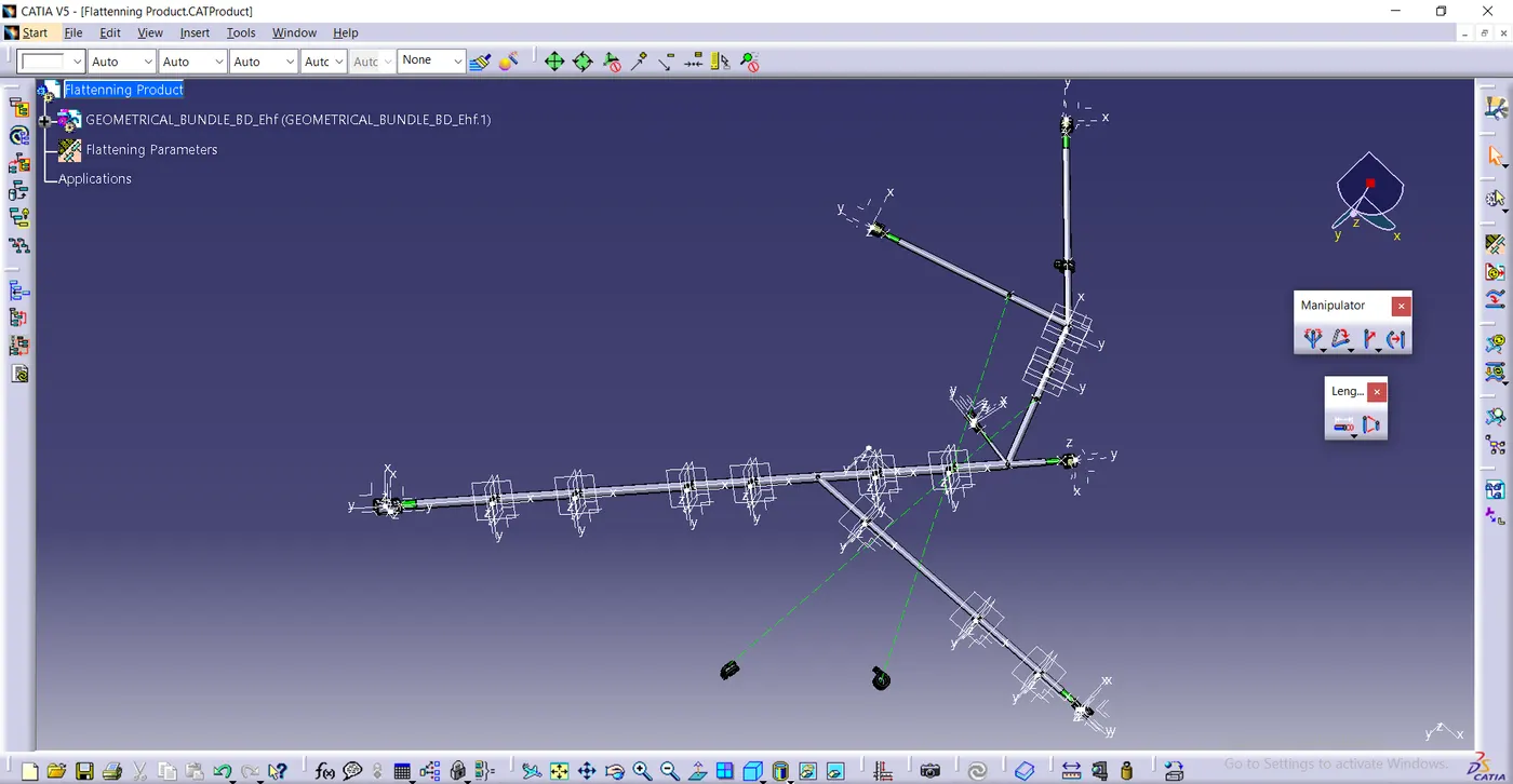
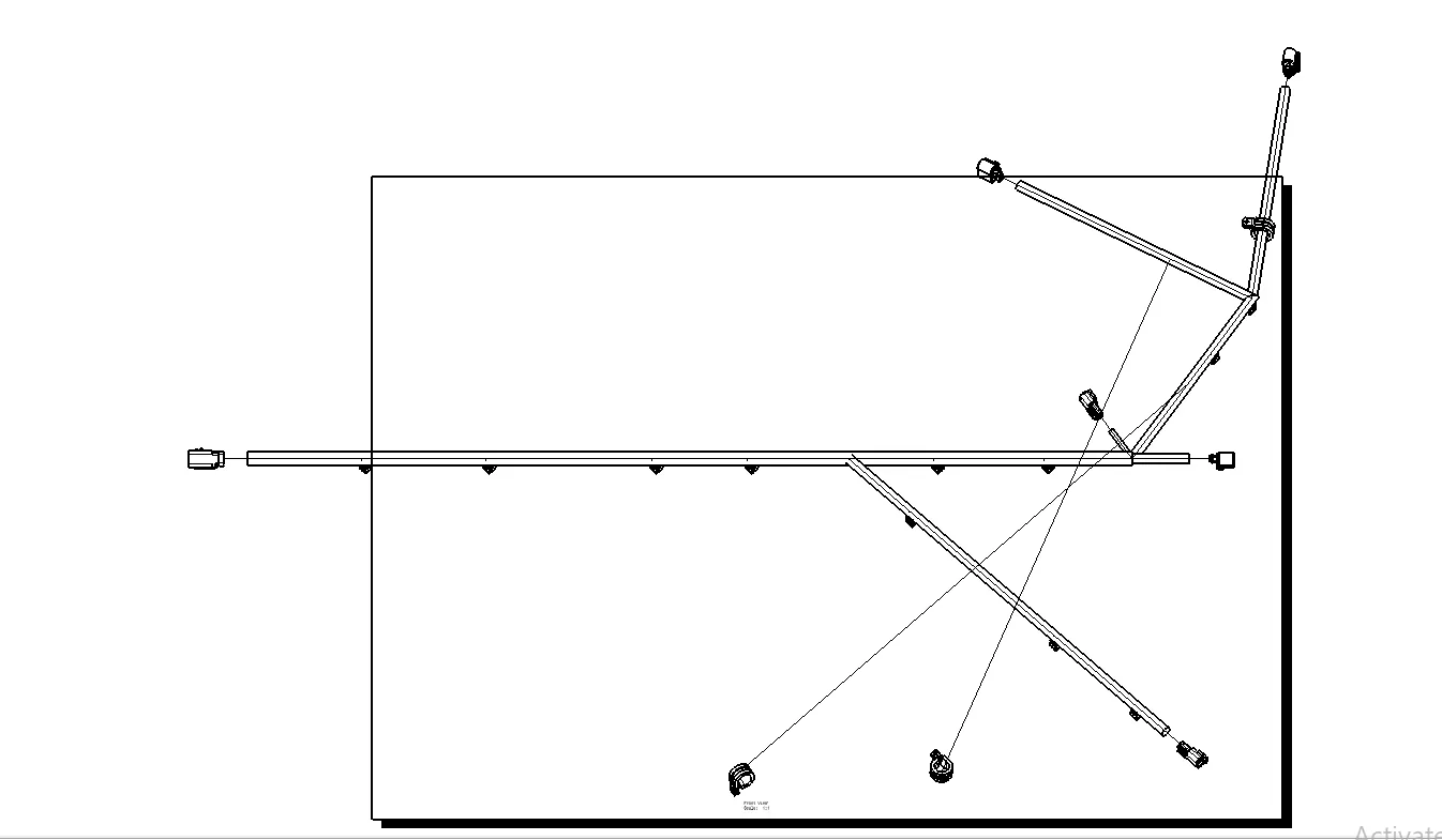
Below is the Flattened drawing of the wiring harness.
Conclusion
The Project in which routing the wiring harness on given Backdoor and prepare flatten view drawing in CATIA V5 is completed considering all types of packaging rules for routing the harness.