Project 2
AIM
1. Initiate a rough concept of Fixture design with reference to all the inputs provided for the given Car panel.
2. Complete 3D finish work.
3. Complete 2D finish with Output documentation.
INTRODUCTION
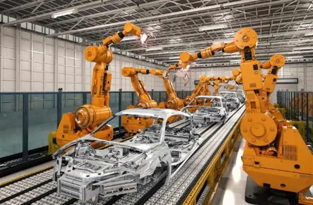
BIW ( BODY IN WHITE )
Body in White (B.I.W.) refers to the welded sheet metal components which form the vehicles structure to which the other components will be married, i.e., engine, chassis, exterior and interior trim.
BIW refers to the stage in automotive design or automobile manufacturing in which the car body sheet metal (including doors, hoods, and side closers) has been assembled or designed but before the components (chassis, motor) and trim (seats, electronics items etc.) have been added. All activities in the production of a vehicle body before it goes to the paint shop are done in a body shop. The equipment used in the automotive industry has to meet the requirements related to the part’s weight and dimensions but also to the high production rates and high precision.
BIW Parts:
there are 5 majors parts in BIW as mentioned below
1. Body sides
- Body side outer
- Body side inner
2. Under Body
- Front end under frame ( Enigine compartment )
- Main frame
- Rear end under frame ( Rear Compartment )
3. Closures
- Front door
- Rear door
- Hood
- Deck lid
4. Roof
- Inner roof
- Outer roof
5. Fender
FIXTURE & ITS TYPES
Fixture is a device whichh hold the work piece to be processed (Welded) by using 3-2-1 principle.
In general, a welding fixture (tool) consist of no. of units together to hold the car panel and is mounted on a base unit. Welding fixtures are normally designed to hold and support the various components (workpieces) to be welded. It is necessary to support them in a proper location which is capable of preventing distortions in a workpiece during welding. For this the locating elements need to be carefully placed, clamping has to be light but firm, placement of clamping elements has to be clear of the welding area and the fixture has to be quite stable and rigid to be quite stable and rigid to withstand the welding stresses.
Types of fixtures
- Production fixtures - These fixtures are used during the time of mass production. Before mass production all the difficulties in manufacturing and errors in the results are noted for the initial batch production and based upon it the fixture is modified to obtain defect free parts during the time of mass production.
- Pre production fixtures - These fixtures are used for initial batch production to study the feasibilty.
- Checking fixtures - These fixtures are used for the car panel geometric inspection purpose.
Basic principle of fixture design
The design intent of the fixture is considered on locating the work piece in a proper orientation and fixing it on the fixture to perform the desired operation on the work piece.
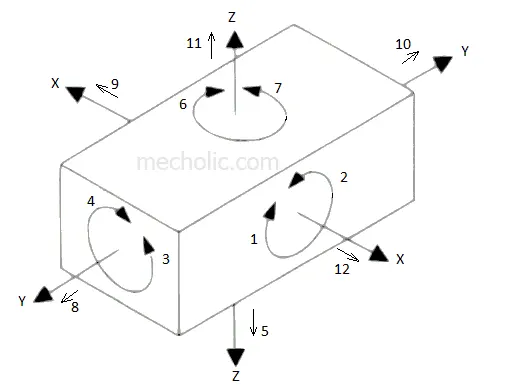
A free body possess 12 Degrees of freedom.
Six transational which are +X, -X, +Y, -Y, +Z,-Z
Six rotational which are Clockwise (CW) X, Anticlockwise (ACW) X, CW Y, ACW Y, CW Z, ACW Z.
So the 12 DOF should be restricted for the workpiece in a fixture.
Types of BIW Stations
The BIW assembly line is divided into sevral zones where different types of panels are joined together in each zone. Each zone has several stations which are :
1.Tool station
A tool is a fixture which consists of no. of units together to hold a car part in general.
Types of Tool station:
a. Geo tool fixture : A geo tool is a fixture in which the geometry of the panels which are welded together is defined accurately. Teh pin tolerance for a geo pin will be of closer tolerance i.e. 0.15 in general.
For ex; Consider panel hole size 20mm, the pin diameter should be 19.85mm.
b. Respot tool fixture : A respot tool is a fixture in which the remaining weld spots which are not achieved in geo tool are welded for the pre welded panel from the geo tool. The pin tolerance for a respot pin will be of tolerance with -0.28 in general.
For ex; Consider panel hole size 20mm, the pin diameter should be of 19.72 mm.
c. Marriage tool : A marriage or hemming tool is a fixture in which the inner panel assembly and outer panel assembly are joined together fixture. These are done by welding or hemming in case of closure panels. In a marriage tool fixture the side bodies, under body, front body and rear body are joined together.
d. Framer tool fixture : A framer tool fixture is a fixture in which a roof is joined with output achieved from the marriage tool fixture.
e. Checking station Tool: A checking station tool is a fixture which is used to check the automotive parts or assemblies, ensuring all the coordinates, relative dimensions and positions as per the tolerances. A checking station can be a gauge type, fixed type and automated checking type.
2.Gripper stations
A gripper is a device or a fixture which holds the car panel and is fixed to the manipulating end of a robot or an end effector. Also known as EOAT - End of arm tooling.
Types of grippers:
a. Material handling grippers: Material handling grippers are designed for handling the car panel from one tool (station) to other tool (station)
b. Process grippers : Process gripper are designed for handling the car panel from one tool (station) to other tool (station) and in addition to that it undergoes processes like pedestal welding, pedestal riveting, gluing sealing etc.
c. Combo gripper : Combo gripper are designed for handling the car panel from one tool (station) to other tool (station) , Also with a combination of weld gun at another side of the gripper for welding.
d. Dual gripper : Dual gripper are designed for handling the car panel from one tool (station) to other tool (station), with two sided gripper.
3.Stands stations
a. Gluing and sealer stand : Gluing gun or sealer gun is fixed to a welded or standard stand which is grouted to the floor.
b. Docking stand : When robots are selected for multitasking like material handling and welding, which cannot carry both due to some limitations (pay load capacity of the robot or space constraint) the robot will drop and pick the gripper or gun after completing the respective operation with the help of docking stand.
c. Date stamping stand : The panel will get the date embossed on it,with the help of date stamping device mounted on the date stamp stand
d. Pedestal stand : Weld gun is mounted to a fixed stand which is grouted to the floor permanently, where the process gripper carries the car panel to weld the spot with this fixed weld gun.
4. Miscellaneous stations
a. Curing : Curing stations holds the workpiece for curing after gluing or welding is done on the workpieces so that the glue or weld undergoes curing.
b. Buffer stand : Buffer stand is used to store the workpieces so that the flow of the assembly line is maintained during the process with no short of workpiece.
c. Conveyers : Conveyers are the rotating belts which carry the workpiece from one tool (station) to other tool (station).
d. Take out trolleys : Take out trolley is used to take the car panel out from the robotic working cell between the cycle for inspection purpose.
PIN UNIT
Pin unit is used to lock the rotational position of panel. Round Pin is used to control panel in two directions while Diamond Pin is used to control panel in one direction.
Types of pin unit
1.Fixed pin unit
A pin unit in which pin's position is fix, is called Fixed Pin Unit. Pin unit is used to lock the rotational position of panel. Round Pin is used to control panel in two directions while Diamond Pin is used to control panel in one direction.
2. Retractable pin unit
Retractable Pin unit consist one Pin cylinder which operates the pin in one direction. In this unit Pin is directly mounted on the cylinder and it is must to have pin and cylinder with the hole or slot of the panel. Pin cylinder is controlled in two directions with the help of shimming.
Parts of pin unit
Pin: Pins are used to locking the rotational movement of the panel. Generally there two types of Pins, one is Round Pin and another one is a Diamond pin
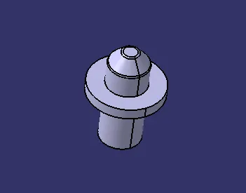
Pin Retainer: Pin Block is also called Pin Retainer. This block holds the pin and restricts the rotational motion of the pin.
Shims: Shims are typically used in order to support, adjust for better fit, or provide a level surface. Shims may also be used as spacers to fill gaps between parts subject to wear.
L blocks: L blocks are mounted on any block or plate with Shimming, So that height of mylar can be adjusted accordingly at the assembly level.
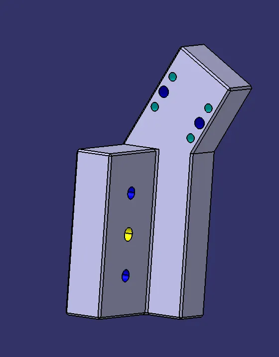
Blades: Blade is a part like a plate,which connects the parts of a unit to a riser. In general, the blade can either be make part or a standard part.

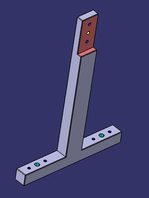
Riser: The part which is mounted on the base plate and holds a clamp or pin cylinder on it, is called Riser.
Design methodologies
- It is necessary to have two pins to locate a car panel. One pin must arrest 4 ways and the other must arrest 2 ways of a car panel.
- Pin should engage 3 - 5 mm from car part entry surface.
- All pins should be accommodated with 2 ways adjustable shims irrespective of direction of arresting.
- Round pin should be used in case of 4 way arresting of car part if the hole is round.
- Round pin should be used in case of 2 way arresting of car part if the hole is slot.
- Diamond pins can be used for 4 way arresting of car part only if the hole is round.
- Diamond pins can be used for 2 way arresting of car part only if the hole is slot.
FULL ASSEMBLY
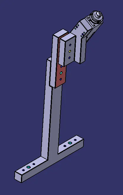
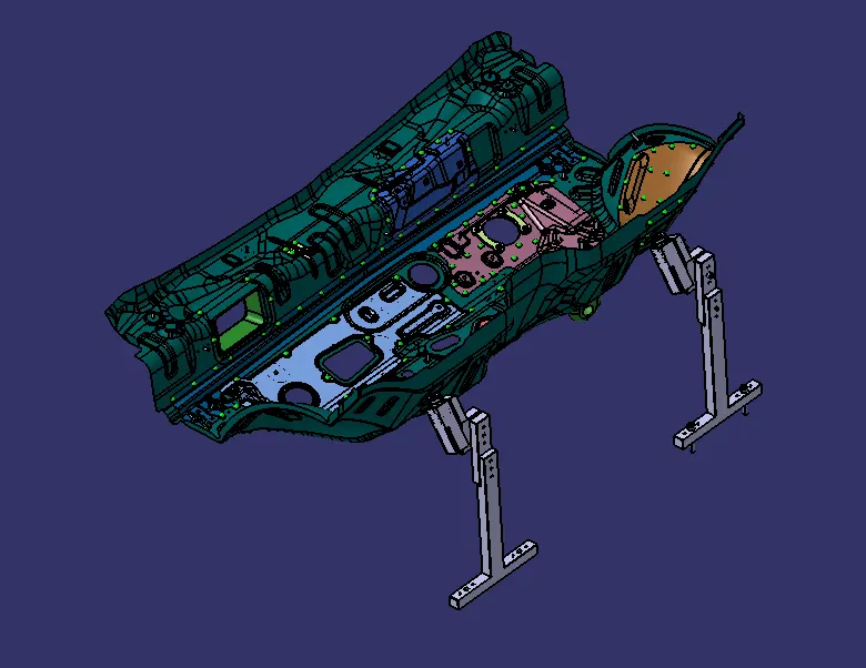
FULL ASSEMBLY WITH CAR PANEL
REST UNIT
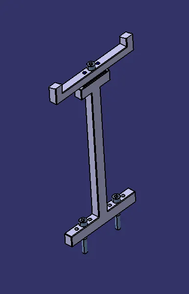
Rest unit are the unit designed just to support the car panel from the bottom. Which includes Mylars , Risers & Blocks etc.
Part of Rest unit
Finger / mylars : Mylars are the part which holds the car panel. There are two types of mylars : Clamp mylar & Rest mylar. The mylar which will be mounted with the clamp is the clamp mylar & the mylar which is rested is rest mylar.
Shims: Shims are typically used in order to support, adjust for better fit, or provide a level surface. Shims may also be used as spacers to fill gaps between parts subject to wear.
L blocks: L blocks are mounted on any block or plate with Shimming, So that height of mylar can be adjusted accordingly at the assembly level.
Blades: Blade is a part like a plate,which connects the parts of a unit to a riser. In general, the blade can either be make part or a standard part.
Riser: The part which is mounted on the base plate and holds a clamp or pin cylinder on it, is called Riser.
Design methodologies for Rest unit
- We have to check proper location of Rest unit in the Fixture.
- We have to place it on a straight surface & also have to ensure it have not collides with any others parts of fixture assembly.
- Minimum 30mm distance must be maintain between mounting holes
Basic principle of fixture design
The design intent of the fixture is considered on locating the work piece in a proper orientation and fixing it on the fixture to perform the desired operation on the work piece.
A free body possess 12 Degrees of freedom.
Six transational which are +X, -X, +Y, -Y, +Z,-Z
Six rotational which are Clockwise (CW) X, Anticlockwise (ACW) X, CW Y, ACW Y, CW Z, ACW Z.
So the 12 DOF should be restricted for the workpiece in a fixture.
REST UNIT 1
REST UNIT 1 WITH CAR PANEL
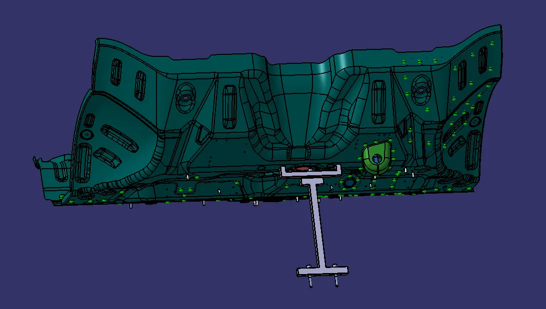
REST UNIT 2
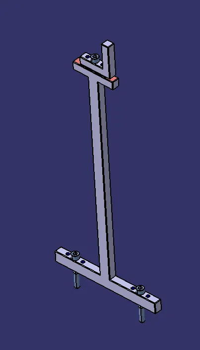
REST UNIT 2 WITH CAR PANEL
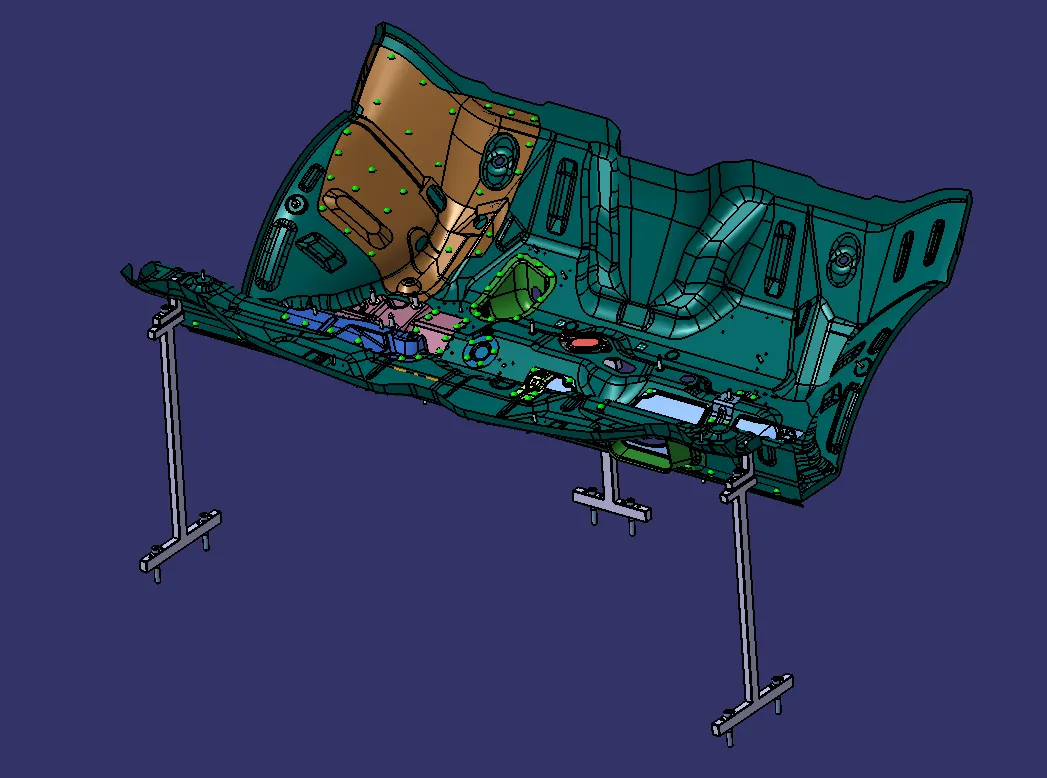
CLAMP UNIT
A clamp unit is a unit designed to clamp or hold the car panel with NC blocks / mylars / rest by using a pnewmatic clamp cylinder.
Types of clamp unit
- Power clamp unit
- Swivel claamp unit
Parts of power clamp unit
1. Pneumatic Cylinder :
The pnematic cylinder converts the pressure energy of compressed air medium into mechanical energy in form of linear or rotary motion.
2. Clamp arm:
Clamp arm is a arm which is assembled with the cylinder , which gets connected to the clamp mylar with help of screw , nuts or bolt etc. It can rotate upto 180 deg to perform the operation of clamping & fixing. It is one the major part & important part of clamp unit.
3. Finger / mylars :
Mylars are the part which holds the car panel. There are two types of mylars : Clamp mylar & Rest mylar. The mylar which will be mounted with the clamp is the clamp mylar & the mylar which is rested is rest mylar.
4. Shims :
Shims are the reactangular blocks that are placed between two parts to provide proper support to the parts & to be merge properly. Shims are in set of five packs thar are 2mm , 1mm , 1mm , 0.5mm , 0.5mm etc.
5. Riser :
The part which is mounted on the base plate and holds a clamp or pin cylinder on it, is called Riser. Riser can be Standard Part or manufactured part, it varies from project to project. A riser can be a Single part or welded part. Standard risers also have various shapes and sizes.
Design methodologies for Clamp unit & Rest unit
- We have to check proper location of clamp unit in the Fixture.
- We cant place the clamp unit on any curved or uneven surfaces , on the emboss surface etc.
- We have to place it on a straight surface & also have to ensure it have not collides with any others parts of fixture assembly.
- Minimum 30mm distance must be maintain between mounting holes
CLAMP UNIT 1
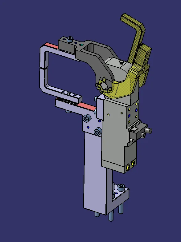
CLAMP UNIT 1 WITH PANEL
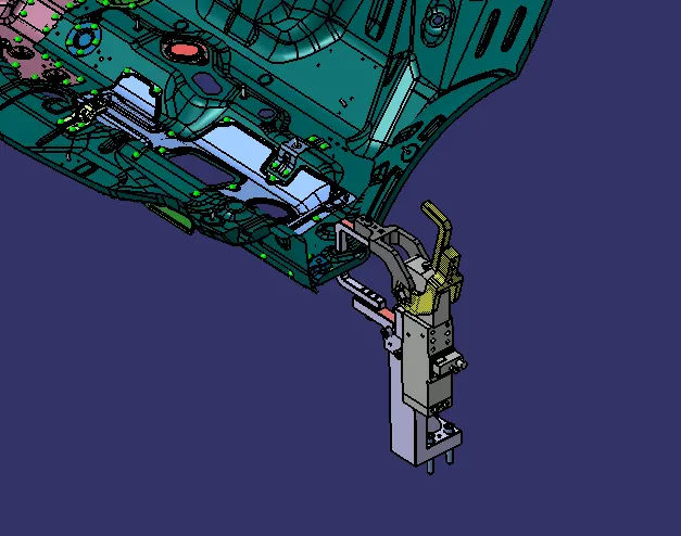
CLAMP UNIT 2
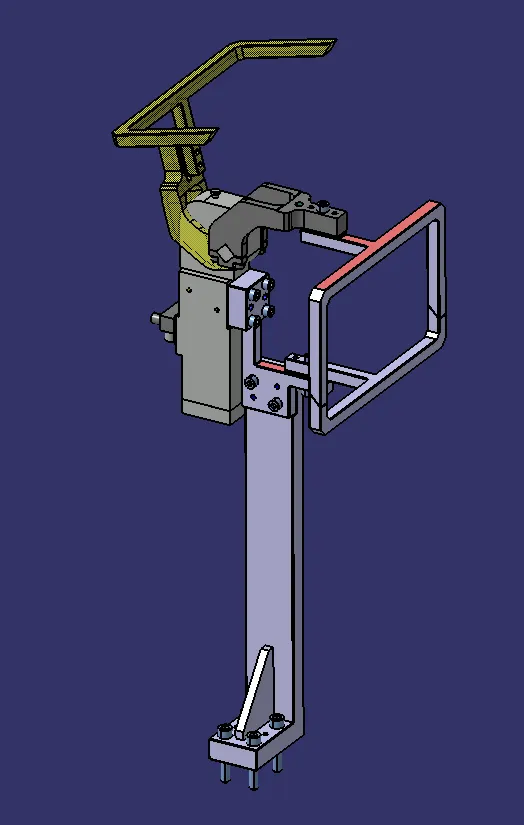
CLAMP UNIT 2 WITH PANEL
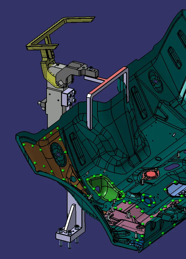
BASE UNIT
A base unit is the unit designed to mount all other units like clamp unit, pin unit, rest unit etc. of the tool also other parts necessary for a tool like pneumatic valave box,trunking cable path will also be mounted on to a base unit.
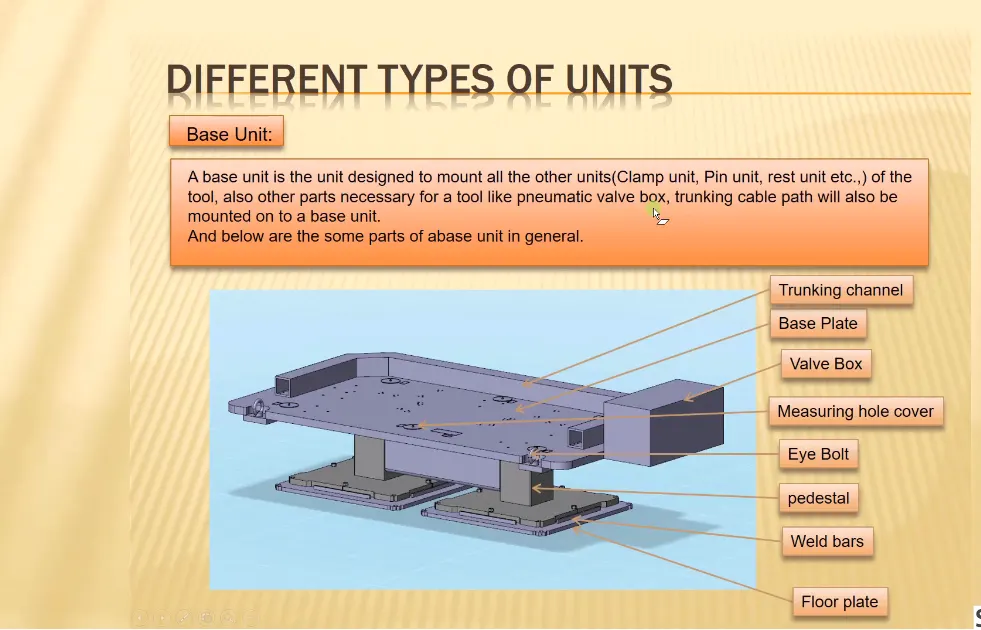
Typical parts of the Base Unit:
- Trunking channel
- Base plate
- Valve box
- Measuring hole cover
- Eye bolt
- Pedestal
- Weld bars
- Floor plate
Points need to account while designing a Base unit
- Working height: It depends on the nature of the manual or robotic welding fixture. for manual fixture we need to consider the working height 850-1100mm depending upon the height of the worker stanadard of a specific country will apply( in few countries human height is higher or lower eg.(US, Japan). If base unit structure is made with base plate having tubular structure welded below it, we can reach to height 100mm to 250mm. In this case to reach the working working height we need to provide additional some leg structure which may have to and bottom plate welded to the tube.
- As designer it is important to know how big base plate or bigger base welded structure will be handled during the fabrication and handling process. Special care need to take care of flatness if the base size is very long.
- Depending upon the weight eyebolt size is selected for lifting holes on the base plate. Generally four eye bolt provision is made. You also need to select the location of eye bolt considering the rope/belt used while shifting the structure or complete fixture are not damaging any units (rest,clamp or location units) nearby.
- Only base plate or welded structure. Depending upon the componenet size and weight of the total units you can decide whether you need a fabricated base or just plate. Mostly fabricated bases are used made of square or rectangualr tube with the plate.
- Most of the OEM makes 4 dowel holes at 4 corner and put small aluminium plate marking x,y and z coordinates of dowel holes. If the base length is too long few OEM's follow the methodology of having holes at 500mm distance.
- The best unit of the fixyure must be strong enough so that deflection of the fixture is as minimum as possible. The deflection of a fixture is caused because of forces of welding,clamping of the work piece.
- The base unit of the fixture should have the mass to prevent vibration and chatter.
- The base unit may be built from simple section so that other units may be fastened with screw or welded necessary. Those parts of the fixture that remain permanently with the fixture may be welded. Those parts that need frequent changing may be held with screws.
- The base unit should be paralled to the floor, to adjust this there should be provision of the height adjusting mechanism.
BASE PLATE DESIGN
- A base plate size should cover all the units with its outer periphery including opening.
- A base plate is preferred to be designed with respect to BCS coordinates.
- A base plate should be drilled with datum holes/measuring holes in line with a pitch of 1000mm in general.
- Number of datum holes is depend on the size of the boxplate.
- Datum hole should be drilled at nominal value of coordinates and in terms of 50 & 100 in general Ex. X= 100, Y=-600, Z=250.
- Datum holes should be drilled with diameter 100mm away from the other unit.
- Datum holes should be covered with cover plates.
PEDESTAL DESIGN
- A standard pedestal can be of different height and different size.
- Depends on the size of the base plate, the number of pedestal varies for load distribution.
- A pedestal are of different types with different inclination.
FLOOR PLATE DESIGN
- There is a clearance of 10mm maintained between the pedestal base plate and the floor plate.
- This clearance will be used by the leveling screws for leveling the entire tool.
- Weld bars are to be weld the positions permanently after leveling is done.
- A weld bar is a plate along the sides of the base plate of the pedestal.
BASE PLATE
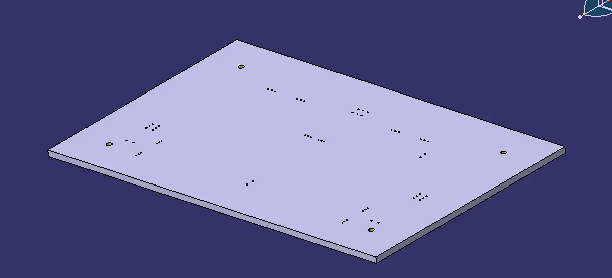
WELD MATE 1
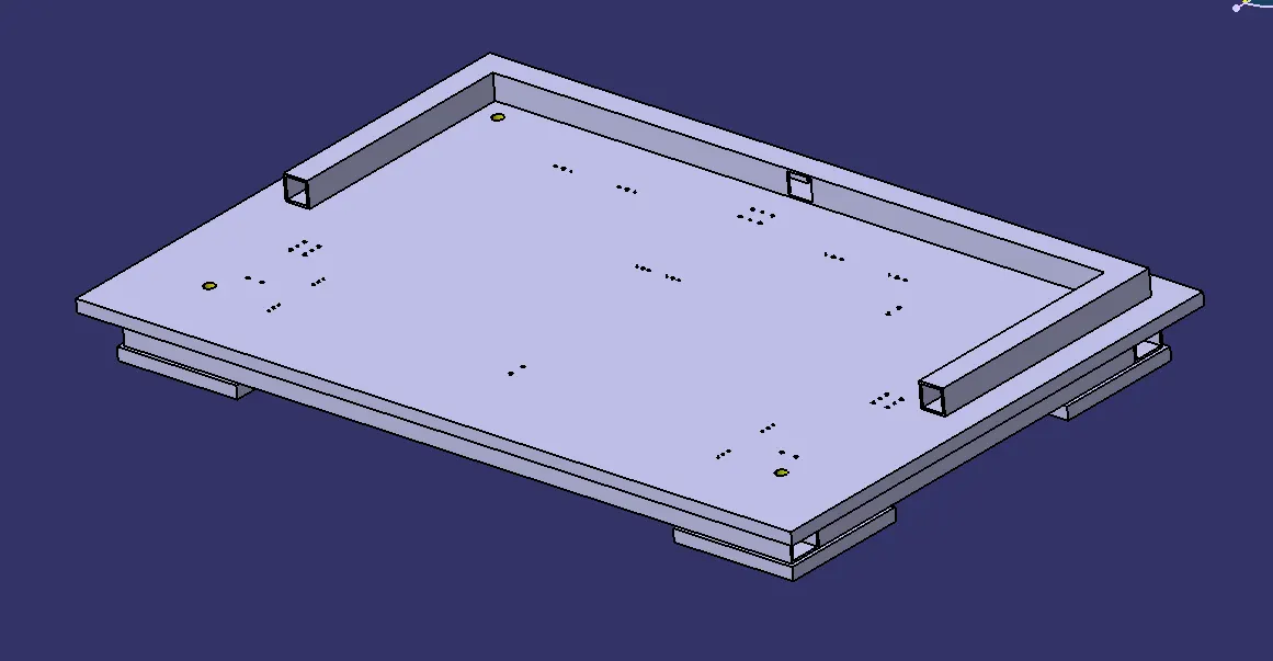
WELD MATE 2
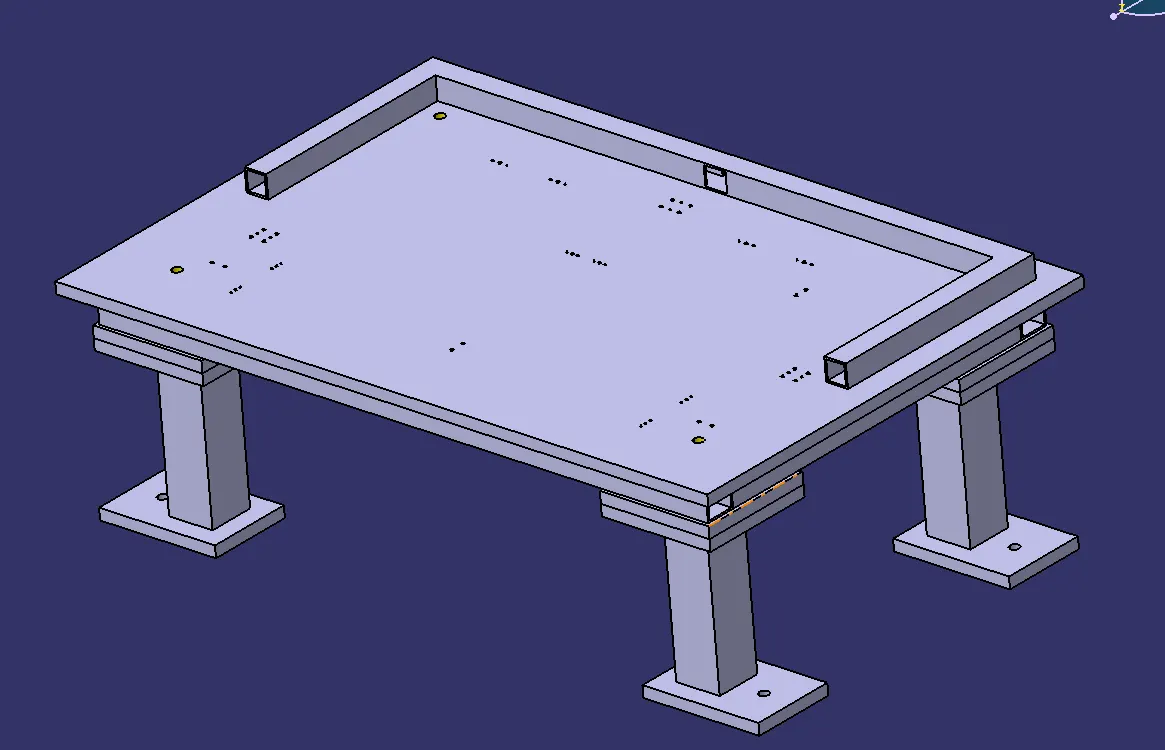
ROUGH LOCATORS
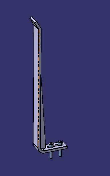
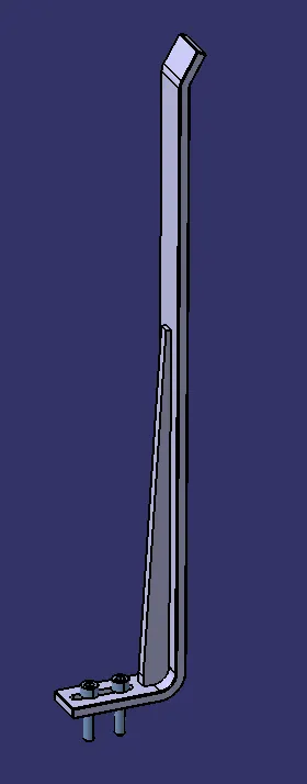
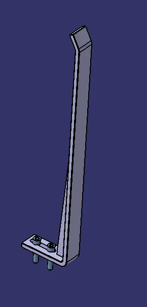
Rough locators are basically used where manual loading of panels are to implemented on the fixture. These are used to guide the panels in correct position & orientation.
These also help for proper Poka -Yoke. Materials used for rough locators are MS or similar metal.
Following points need to be considered while designing the rough locators:
- Height of rough locators should not be more than the permissible ergo height of the fixture.
- The entry point/ top point of the rough locator must be 10mm-15mm above the panel surface.
- Rough locators should have adjustment in the direction of guiding plane.
- 2 mm gap to be maintained between rough locator and panel at the time of design & we can provide adjustment of 5-10 mm in the positive or negative direction of guide plane.
- Rough locators can be rod type or flat type, depending upon the standards and other conditions.
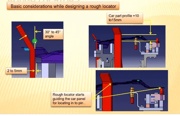
ROUGH LOCATOR 1
ROUGH LOCATOR 2
ROUGH LOCATOR 3
ROUGH LOCATORS WITH PANEL
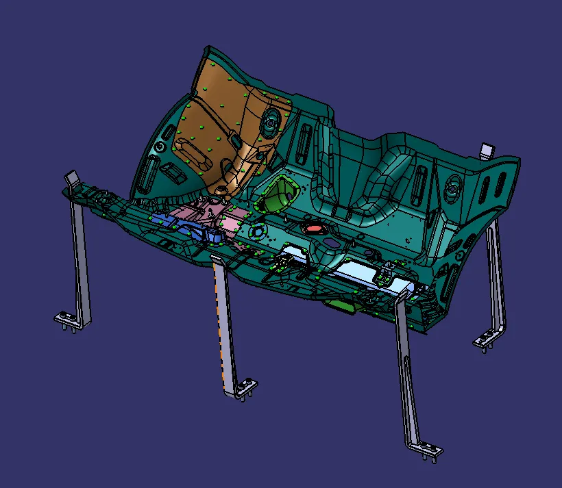
NOTE: 4 rough locators are enough to guide the panel, all locators are checked & located with weld gun feasibility.
3D FINISH
3D finish is a process where the design is being completely finish and to be ready for final simulation & 2d detailing.These is the process before sending the part for final simulation.
In these process the parts are checked for proper clearance and the nominality is also maintained. The machining sides of parts are applied with colour codes for representation.
Parts are checked for hole concentricity & size, standard colour codes are applied for holes and the fastners are also implemented. Renaming of parts is done for easy indentification in assembly.
Following points need to be taken care of while finishing the design:
- Hole concentricity & hole sizes
- Machining area
- Nominality
- Holes colouring standard
- Pneumatic lay-outing
- Gaps checking
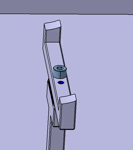
- Fasteners implementation
- Avoiding clash between different parts
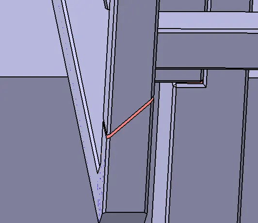
- Mylars splitting as per panel profile
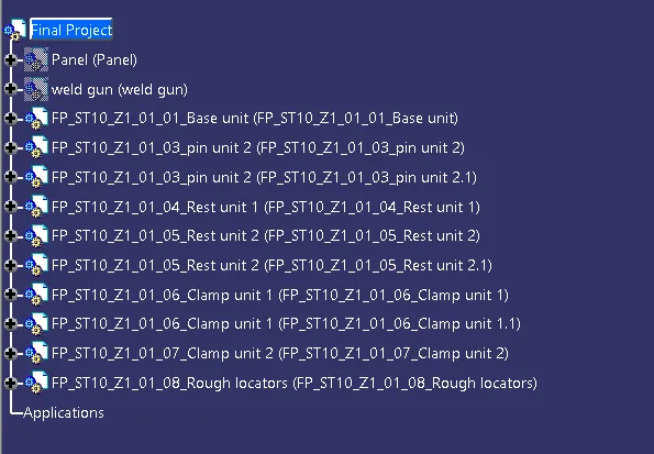
- Proper renaming of parts/assemblies as per the standard
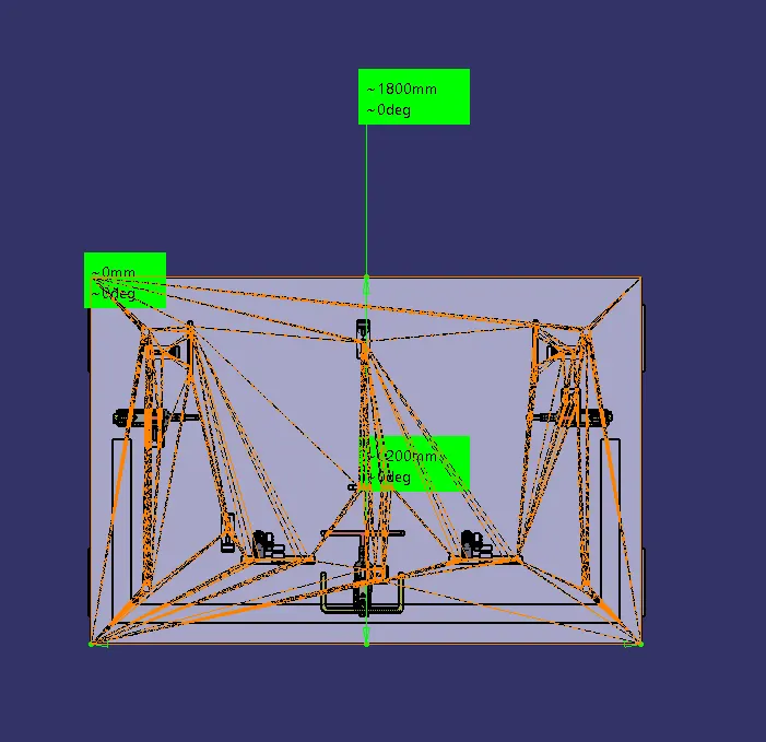
Layout:
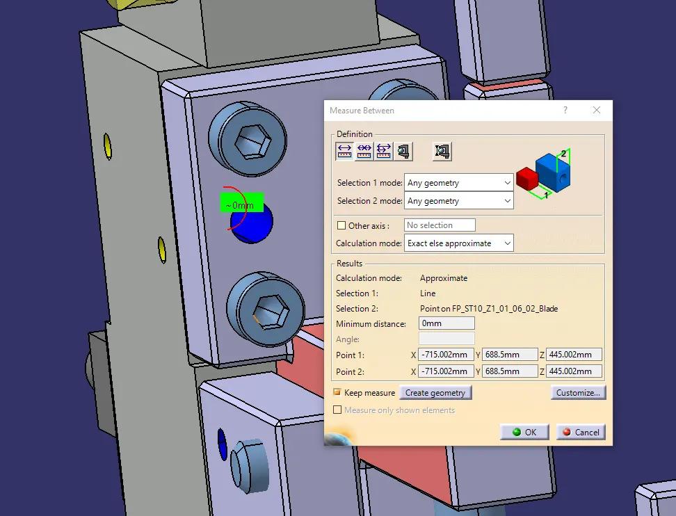
Concentricity:
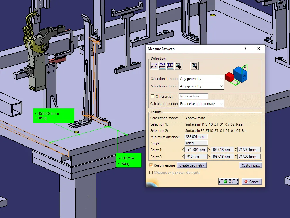
Nominality
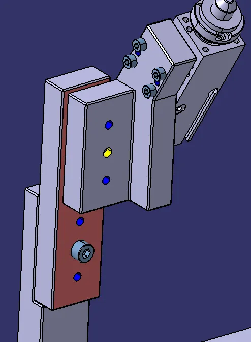
Holes colouring standard:
Pneumatic lay-outing:
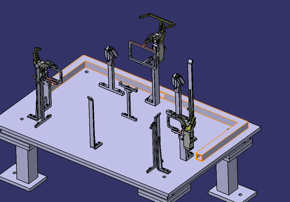
Gaps checking:
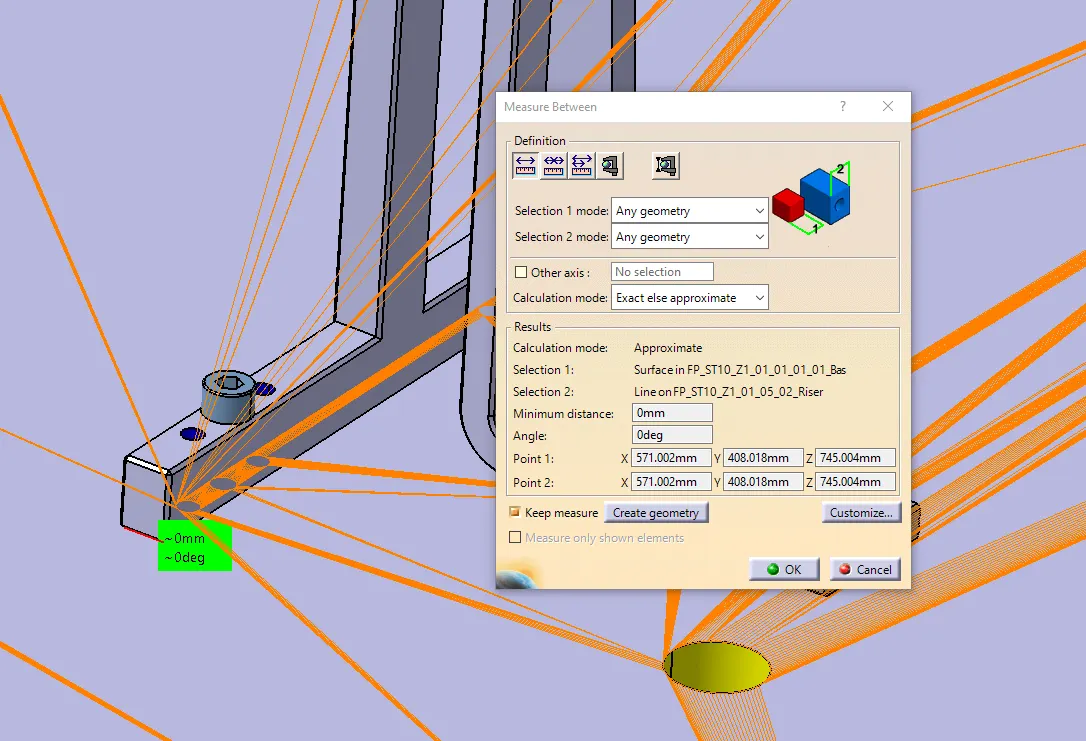
Fasteners implementation:
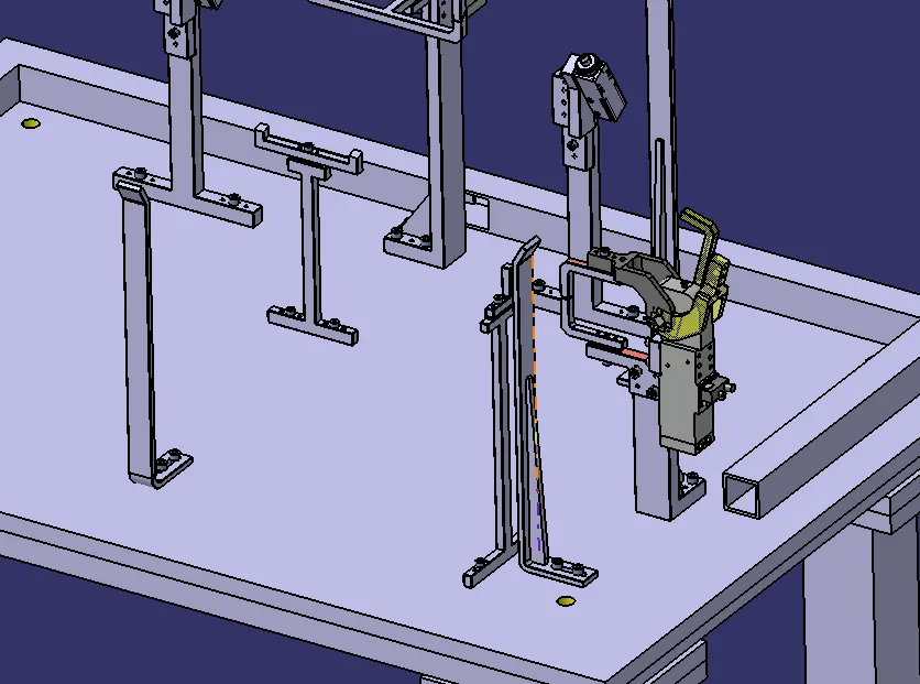
Avoiding clash between different parts:
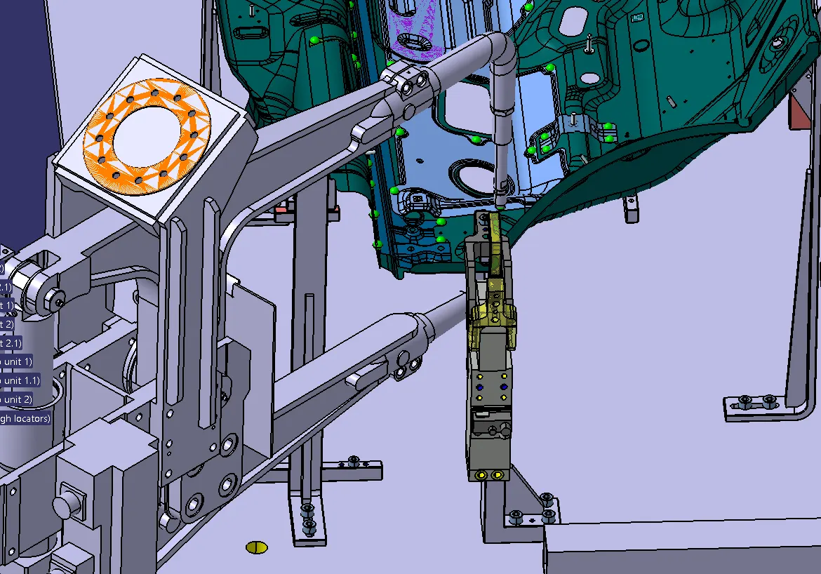
Mylars splitting as per panel profile:
Proper renaming of parts/assemblies as per the standard:
2D FINISH
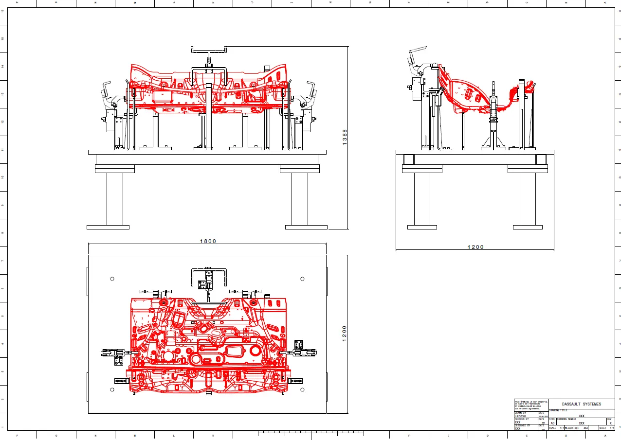
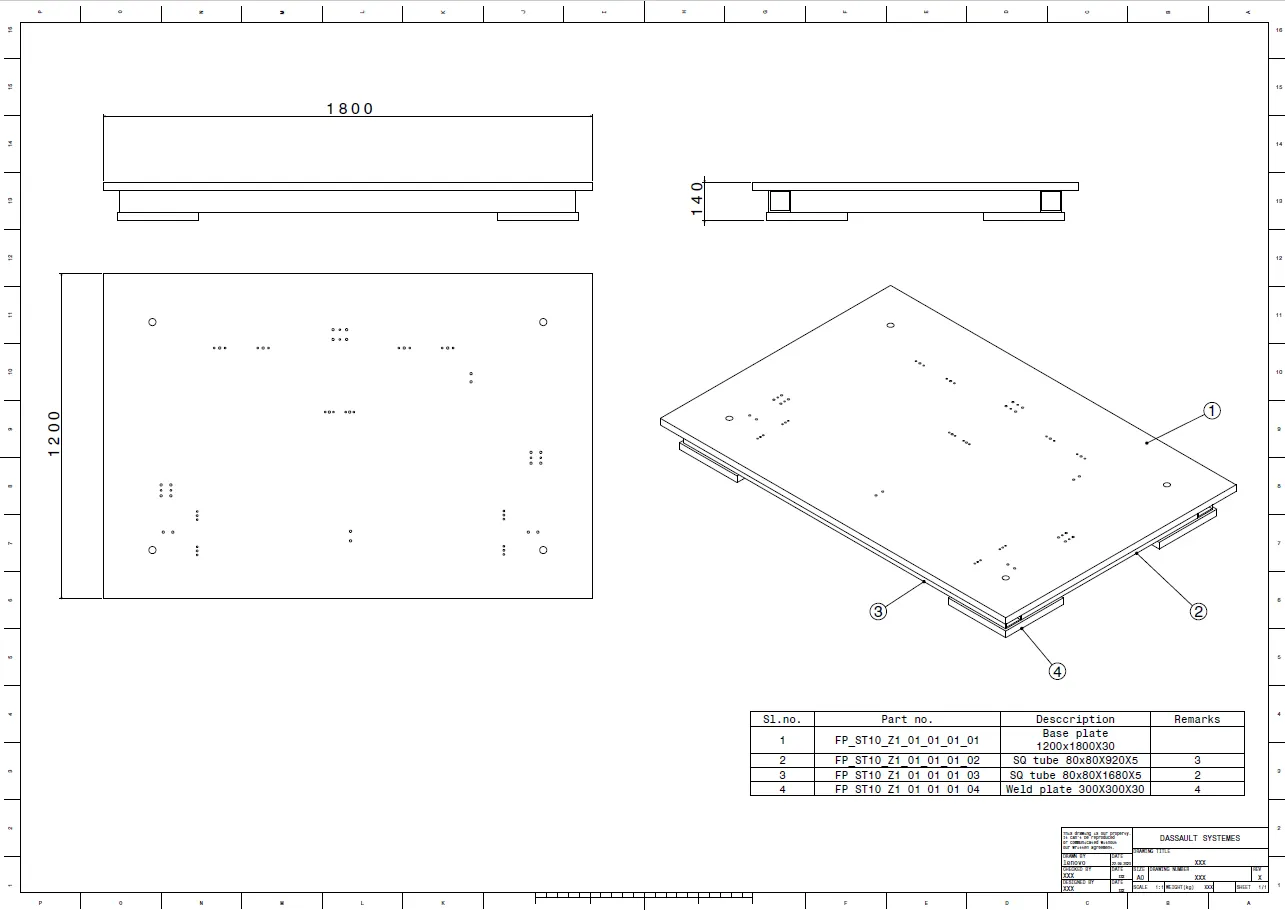
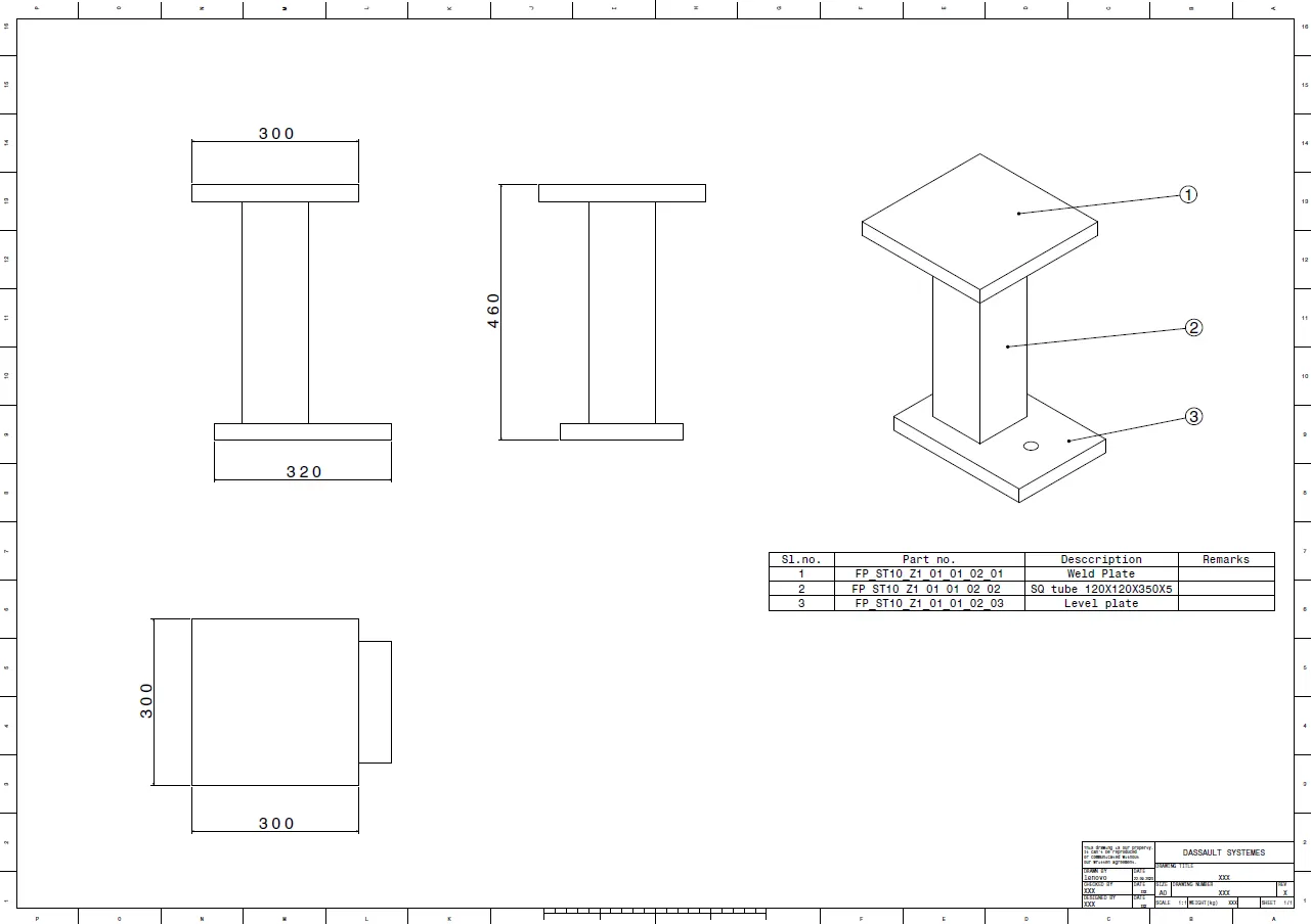
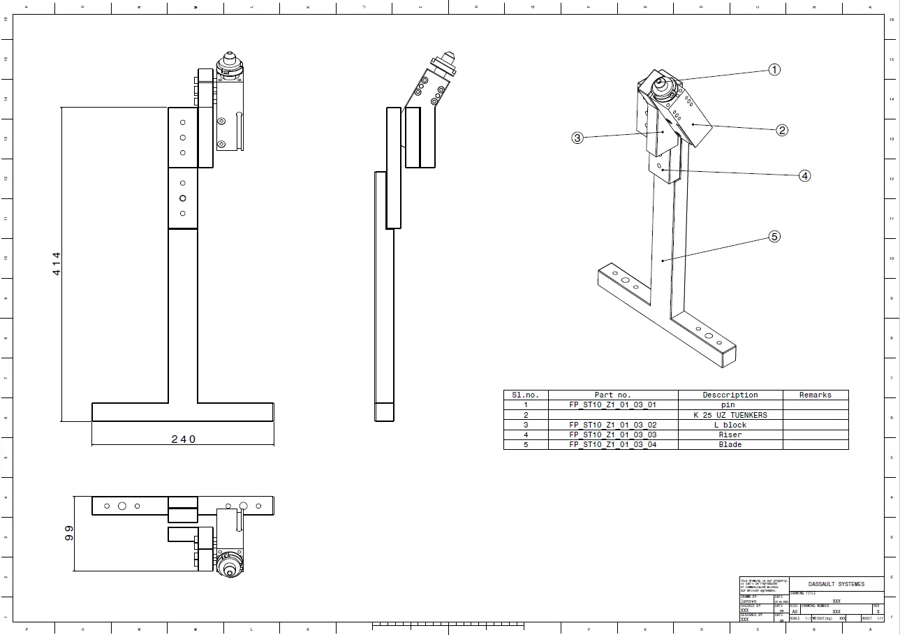
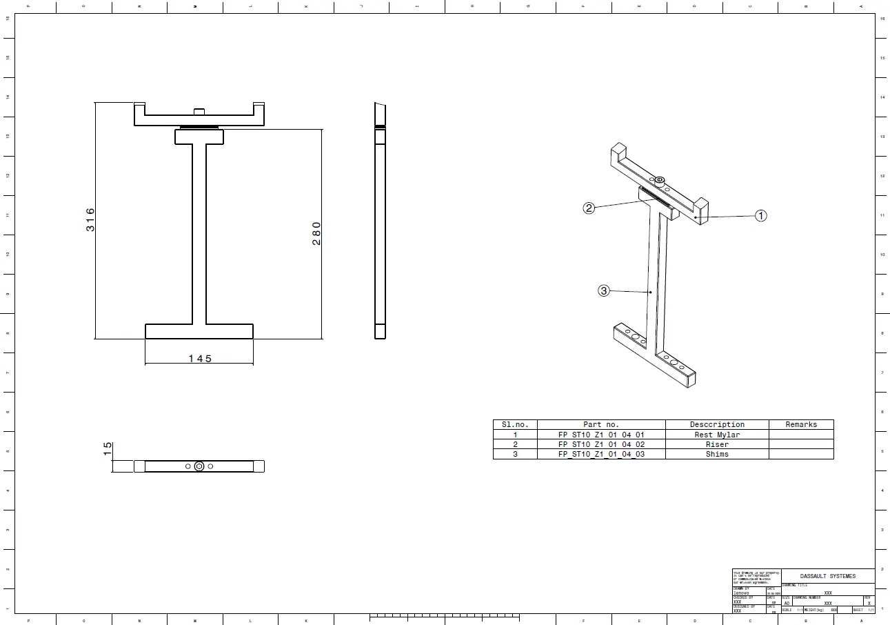
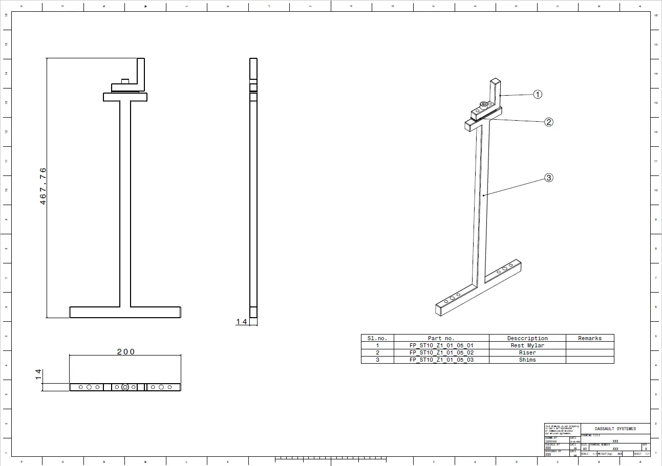
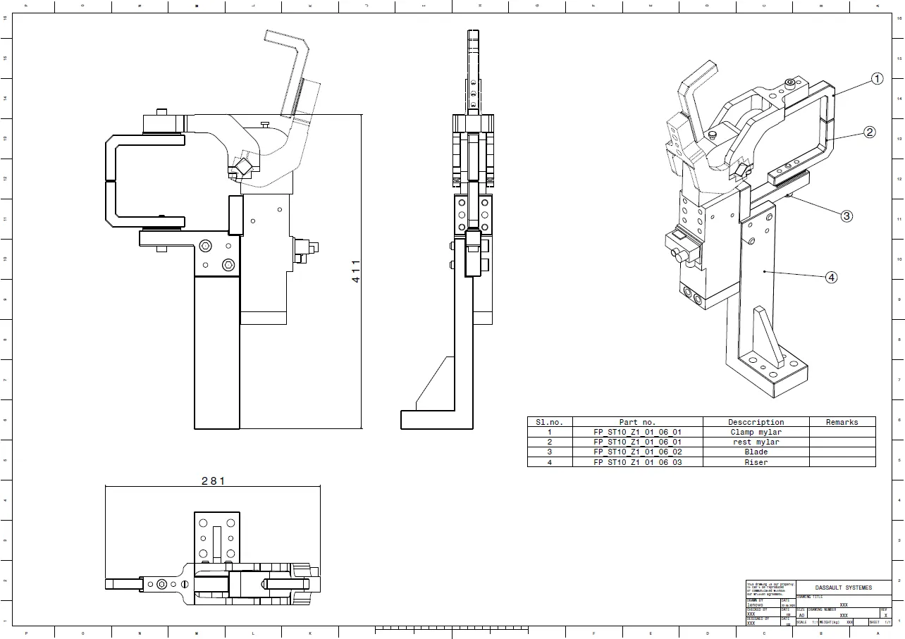
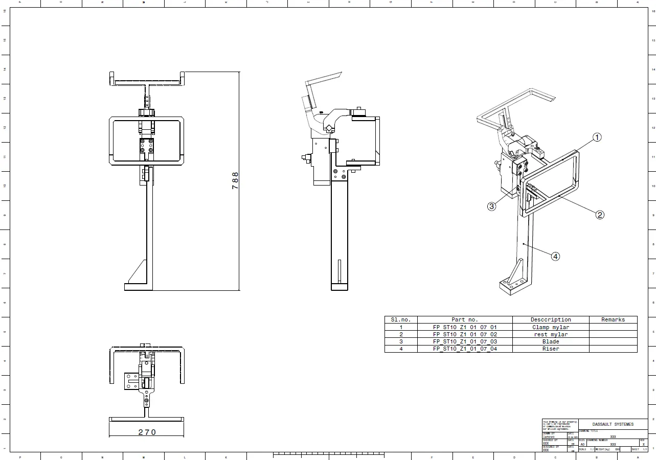
BOM
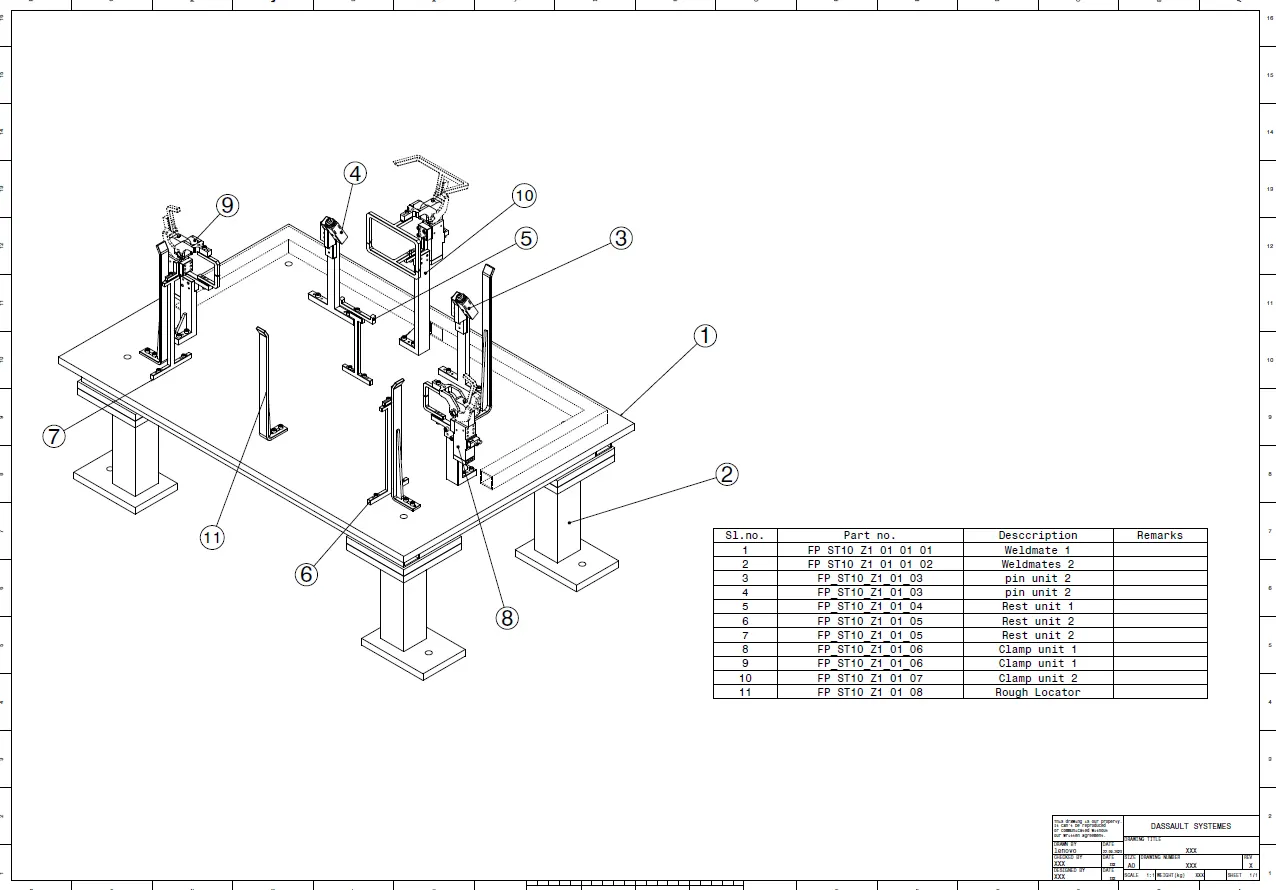
A Bill of Materials (BOM) is a list of all the components and parts needed to manufacture a product or assembly. In a
drawing sheet, the BOM is typically included as a table or list of items, with information such as the part number,
description, quantity required, and other relevant details.
The BOM serves as a reference for designers, engineers, and manufacturers to ensure that all the necessary components
are accounted for and that the correct quantities are ordered or produced. It is also used to track changes and revisions
to the design, as well as to estimate the cost of manufacturing.
In summary, a Bill of Materials is a critical component of a drawing sheet that provides a detailed inventory of the
parts and components required to build or assemble a product.
Uses of BOM
The Bill of Materials (BOM) list is a vital document that is used throughout the product development cycle and is an
essential component of the drawing sheet. Here are some of the key uses of a BOM list:
1) Assembly and Manufacturing: The BOM list provides a complete inventory of all the parts and components required to
assemble a product. This ensures that manufacturers and production teams have all the necessary components on hand
to build the product and that the correct quantities are produced.
2) Cost Estimation: The BOM list is used to estimate the cost of manufacturing a product by tracking the cost of
each component. This information is critical in making decisions about pricing and profitability.
3) Quality Control: The BOM list helps ensure the quality of the finished product by ensuring that all components are
accounted for and that they meet the required specifications.
4) Design and Engineering: The BOM list is an essential tool for designers and engineers as it ensures that all the necessary
components are considered during the design process. It also allows for tracking design changes and revisions, and
provides a comprehensive reference document for future product development.
5) Inventory Management: The BOM list is used to track inventory levels and ensure that there are enough components
on hand to meet production demands.
6) Regulatory Compliance: The BOM list is used to ensure that all components used in the product meet regulatory
requirements, such as safety standards, environmental regulations, and material restrictions.
BOP
TREE STRUCTURE
CONCLUSION
- Various Fixtures like Pin unit, Clamp unit, Rest unit, Rough locators and Base unit are designed.
- 3D Finish procedure is carried out on the assembly by considering standard procedures.
- 2D detailing is created with documentation like part list, BOM and BOP for thr complete fixture assembly.
Note: Uploaded file didnt have car panel .part file because of upload storage. kindly add the component if you want to check.