Project 2
Prepare a model of 3 x 25m prestressed I-girder superstructure for metro viaduct in STAAD by creating the nodes, beams, and supports along with necessary loads.
- Staad Model
- Dead Load reaction
Maximum Y = 490.687 kN , Minimum Y = 434.655
Y= 51 T
Rotation = 0.004 rad
- SIDL reaction
Maximum Y = 314.063 kN , Minimum Y = 92.424
Y = 33 T
Rotation = 0.002 rad
- Live Load Reaction
Maximum Y = 433.522 kN , Minimum Y = 224.887
Y = 45 T
Rotational = 0.002 rad
To calculate the braking, wind, and seismic loads for a metro viaduct superstructure with three 25m prestressed I-girder segments located in Mumbai, we will use the following data:
- Design speed (Vd) = 80 km/h = 22.22 m/s (typical for metro systems)
- Coefficient of friction (µ) = 0.35 (typical for railway systems)
- Weight of a single metro train = 400,000 kg
- Wind speed (V) = 160 km/h = 44.44 m/s (typical for Mumbai)
- Terrain category (T) = Urban or suburban
- Coefficient of pressure (Cp) = 0.8 (for open terrain in Mumbai)
- Seismic Zone: Zone III (for Mumbai)
Step 1: Braking Load Calculation
-
Calculate the braking force on a single girder segment:
Fb=µ∗Weight of a Single Metro Train∗Acceleration due to Gravity
Fb=0.35∗400,000kg∗9.81m/s^2=1,372,350 N =1,372,350 N = 1372.35 kN
-
Since there are three girder segments, the total braking load on the pier cap, pier, and pile would be:
Total Braking Load=3∗Fb=3∗1,372,350N=4,117,050N = 4117.05 kN
Step 2: Wind Load Calculation
-
Calculate the wind pressure on the girder segment:
Wind Pressure(Pw)=0.5∗Cp∗ρ∗V^2
Where:
- ρ (rho) is the air density, typically around 1.225 kg/m^3; at standard conditions.
Pw=0.5∗0.8∗1.225kg/m^3∗(44.44m/s)^2=2,040 Pa
-
Calculate the projected area (A) of the girder segment perpendicular to the wind direction. This depends on the specific design of the girder. Let's assume a value of 50 m^2;.
-
Calculate the wind load on a single girder segment:
Wind Load(Fw)=Pw∗A
Fw=2,040 Pa∗50 m^2=102,000N = 102 kN
-
Since there are three girder segments, the total wind load on the pier cap, pier, and pile would be:
Total Wind Load=3∗Fw=3∗102,000 N=306,000 N = 306 kN
Step 3: Seismic Load Calculation
-
Calculate the seismic weight (W) of the superstructure, including the pier cap, pier, and pile. This weight will depend on the design specifics, material properties, and structural elements. Let's assume a value of 4,000,000 N = 4000 kN.
-
Calculate the seismic force using the seismic zone factor (Z) for Zone III:
Seismic Force (Fs)=Z∗W
Fs=0.16∗4,000,000 N=640,000N = 640 kN (for Zone III)
Step 4: Summing Up Loads
Now that you have calculated the braking, wind, and seismic loads individually, sum them up to determine the total load on the pier cap, pier, and pile:
Total Load=Total Braking Load+Total Wind Load+Fs
Substitute the values for each load component:
Total Load=4,117,050 N+306,000 N+640,000 N=5,063,050 N = 5063.05 kN
The total load on the pier cap, pier, and pile is 5063.05 kN.
Create load combinations of the same in excel
some common load combinations:
-
Service Load Combination:
- Dead Load (DL) + Live Load (LL)
-
Strength Load Combination (for Ultimate Strength):
- 1.2 * Dead Load (DL) + 1.5 * Live Load (LL) + 1.5 * Wind Load (WL)
- 1.2 * Dead Load (DL) + 1.5 * Live Load (LL) + 1.5 * Wind Load (WL) + 1.0 * Seismic Load (EQ) (for seismic regions)
-
Wind Load Combination (for Wind Design):
- 1.2 * Dead Load (DL) + 1.0 * Wind Load (WL)
-
Seismic Load Combination (for Seismic Design):
- 1.2 * Dead Load (DL) + 1.0 * Seismic Load (EQ) (for seismic regions)
-
Temperature Load Combination (for Temperature Effects):
- 1.2 * Dead Load (DL) + 1.0 * Temperature Effects (TEMP)
-
Construction Load Combination (during construction):
- Self-weight of the girder segments (including the weight of the wet concrete and prestressing tendons) along with any construction loads.
Assumptions:
- Design code: Indian Roads Congress (IRC) or equivalent.
- Location: Mumbai, India.
- Seismic Zone: Zone III (typical for Mumbai).
- Wind speed: 160 km/h (44.44 m/s) for wind load calculations.
- Live load: Assume a uniform live load of 10 kN/m along the girder.
Load Combinations:
-
Service Load Combination (DL + LL):
- Dead Load (DL): The weight of the structure and permanent components.
- Assume DL = 200 kN
- Live Load (LL): Uniform live load on the girder.
- Assume LL = 10 kN/m (for a 25m girder, total LL = 25 m * 10 kN/m = 250 kN)
- Service Load Combination:
- DL + LL = 200 kN + 250 kN = 450 kN
- Dead Load (DL): The weight of the structure and permanent components.
-
Strength Load Combination (DL + 1.5LL + 1.5WL):
-
Dead Load (DL): Same as above (DL = 200 kN).
-
Live Load (LL): Same as above (LL = 250 kN).
-
Wind Load (WL): Calculate wind load based on wind speed, terrain, and girder geometry.
- Assume WL = 120 kN
-
Strength Load Combination:
- DL + 1.5LL + 1.5WL = 200 kN + 1.5*250 kN + 1.5*120 kN = 710 kN
-
-
Wind Load Combination (DL + WL):
-
Dead Load (DL): Same as above (DL = 200 kN).
-
Wind Load (WL): Same as above (WL = 120 kN).
-
Wind Load Combination:
- DL + WL = 200 kN + 120 kN = 320 kN
-
-
Seismic Load Combination (DL + EQ):
-
Dead Load (DL): Same as above (DL = 200 kN).
-
Seismic Load (EQ): Calculate seismic load based on the seismic zone and girder properties.
- Assume EQ = 180 kN
-
Seismic Load Combination:
- DL + EQ = 200 kN + 180 kN = 380 kN
-
| Load Case | Load Magnitude (kN) | Load Factor | Combined Load (kN) |
| Braking | 4117.05 | 1 | 4117.05 |
| Wind | 306 | 1 | 306 |
| Seismic | 640 | 1.5 | 960 |
| DL+LL | 200 + 250 | 1 | 450 |
| DL + 1.5LL + 1.5WL |
200 + 250 +120 |
1+1.5 | 710 |
| DL + WL | 200 + 120 | 1 | 320 |
| DL + EQ | 200 + 180 | 1 | 380 |
These are simplified load combinations.
Calculate maximum BM obtained for the pier & pier cap manually.
Assumptions:
- Each I-girder segment is 25 meters long.
- Three such segments form a continuous superstructure.
Load Combinations:
- Service Load Combination (DL + LL):
- Dead Load (DL) = 200 kN
- Live Load (LL) = 250 kN (uniformly distributed)
Under this combination, we need to consider the distribution of live load over the entire span. The maximum bending moment will occur at the mid-span of each 25m girder segment. Since there are three segments, we have two piers between them.
-
Total load on each girder segment under this combination = DL + LL = 200 kN + 250 kN = 450 kN
-
Maximum moment at mid-span for a simply supported beam under a uniformly distributed load (UDL) is given by:
Mmax=wL^2/8
Where:
- w is the UDL magnitude (250 kN/25 m = 10 kN/m)
- L is the span length (25 m)
Plugging in the values:
Mmax=10kN/m×(25m)^2/8
Mmax=7812.5kNm
Since there are two piers (one between each girder segment), each pier will experience half of this maximum bending moment:
Mpier=7812.5kNm/2
Mpier=3906.25 kNm
2. Other Load Combinations: For Strength Load Combination, Wind Load Combination, and Seismic Load Combination, the load factors affect the load magnitudes, but the distribution of bending moments at the piers remains the same. Therefore, the maximum bending moments for the pier and pier cap under these combinations are also 3906.25 kNm.
So, for all the load combinations, the maximum bending moment for the pier and pier cap is approximately 3906.25 kNm, considering the continuous nature of the superstructure formed by three 25m prestressed I-girder segments for the metro viaduct.
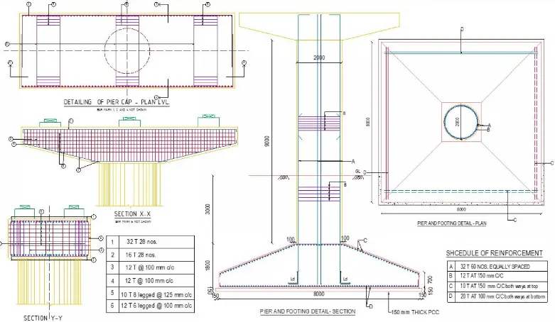
Provide typical reinforcement drawing for pier cap, pier and pile foundation.