Project 2
All representation are as shown above.
The general steps involved in analyzing and designing the bridge:
-
Gather Information:
- Collect all above information about the bridge, including its span arrangement, dimensions, and material properties.
- Obtain information about the live loads (LL) and dead loads (DL) that will be applied to the bridge.
-
Determine Bridge Geometry:
- Define the geometry of the bridge, including the span lengths, support locations, and any variations in the superstructure.
-
Calculate Dead Loads (DL):
- Calculate the dead load of the bridge components, including the weight of the structural elements and the upstand.
- Use the given concrete density (25 kN/m⊃3;) to estimate the weight of concrete components.
-
Calculate Live Loads (LL):
- Determine the live load distribution based on the given live load specification (10 kN/m⊃2;).
- Consider different scenarios for live load placement and combinations.
-
Analyze Structural Elements:
- Perform structural analysis of the bridge components, such as beams, girders, and piers, to calculate internal forces (e.g., bending moments, shear forces) under various load conditions.
- Consider factors such as support reactions, boundary conditions, and load placements.
-
Design Structural Elements:
- Select appropriate structural members (e.g., steel beams, reinforced concrete girders) and design them to safely resist the calculated internal forces.
- Ensure that the selected materials and dimensions meet relevant design codes and standards.
-
Check for Structural Stability:
- Verify that the bridge is stable and does not experience excessive deflection, buckling, or other forms of instability under the applied loads.
- Consider dynamic effects, such as vibration and wind-induced forces.
-
Evaluate Fatigue and Serviceability:
- Check for fatigue considerations, especially if the bridge is expected to experience a large number of load cycles.
- Evaluate serviceability criteria, including deflection limits, to ensure the bridge meets user expectations.
-
Review and Revise:
- Conduct a comprehensive review of the design and analysis to identify any areas that require revision or optimization.
- Make necessary adjustments to improve the bridge's performance and safety.
-
Documentation and Reporting:
- Prepare detailed engineering drawings, calculations, and reports that document the bridge design and analysis process.
- Ensure that all design choices and calculations are well-documented for future reference.
-
Construction and Inspection:
- Oversee the construction process to ensure that the bridge is built according to the design specifications.
- Conduct inspections and quality control checks during and after construction to verify that the bridge meets safety and design standards.
After Studying All data we will proceed for Modelling and design using LUSAS Software:
- To create a preliminary design for the planned bridge vertical and horizontal alignments. And to design the concrete, prestress, and steel components in accordance with pertinent Indian requirements. This includes modelling the bridge with appropriate stages from diaphragm to live load application.
- Since the bridge is symmetrical, it was chosen to merely analyse and design representative spans (few from curved range and few from straight range).
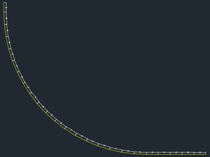
Bridge alignment horizontally as proposed: (From Abutment to Central Steel Span)
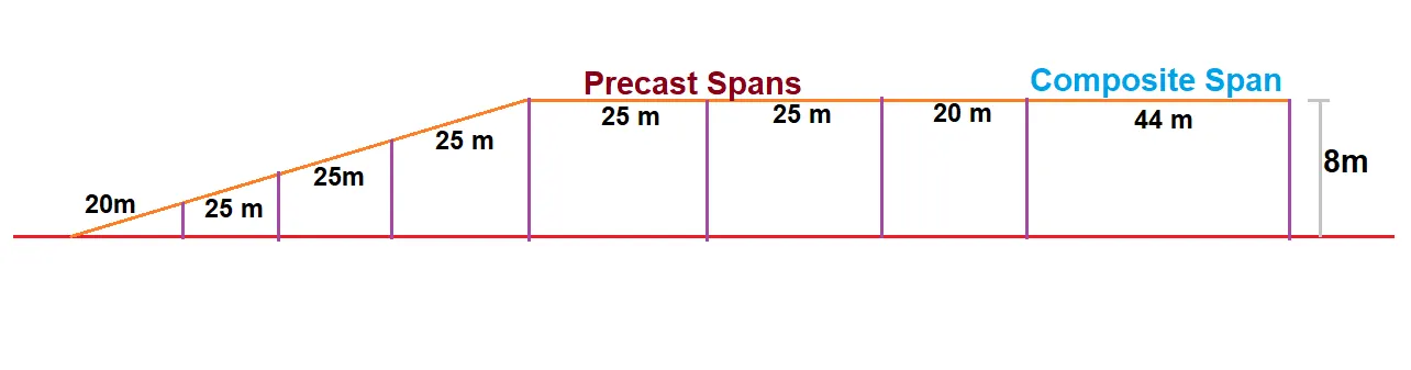
Vertical allignment of proposed bridge: (From Abutment to Elevated Level of Deck):
Only a small number of horizontal alignment and vertical alignment spans will be modelled and created in accordance with the following configuration.
Adopted construction stages as per given details:
(i) Solid diaphragm + post tensioning only stage
(ii) Precast girders + prestress only (to be checked for fresh concrete slab above)
(iii) Composite steel section with joint in overhanging precast girder (to be checked for fresh concrete slab above)
(iv) With concrete slab deck (to be checked for all other imposed loads like asphalt, curb & barrier)
(v) Live load with continuous and discontinuous checks
Loads to be calculated in each stages:
Stage-1
Only solid diaphragms need to have post-tension assignments in their models. Therefore, no load must be applied.
Stage-2
Precast girders must be covered with fresh concrete. This has to be verified as loaded. 200mm thick by 8 metres wide concrete.
8 x 0.2 x 25 = 40 kN/m
We have 2 tub sections, so each precast section will carry 20 kN/m
Stage-3
Steel box girders must be covered with freshly cast concrete. This has to be verified as loaded. 200mm thick by 8 metres wide concrete.
8 x 0.2 x 25 = 40 kN/m
We have 2 box girders, so each composite girder will carry 20 kN/m
Stage-4
The deck slab will behave monolithically with the precast and composite steel after it has hardened. However, the above curb, barrier, and asphalt are imposed loads that must be put permanently.
Curb = 0.3 x 0.35 x 25 = 2.63 kN/m
Barrier = 4 kN/m
Asphalt = 0.127 x 18 = 2.3 kN/m2 (area load)
Stage-5
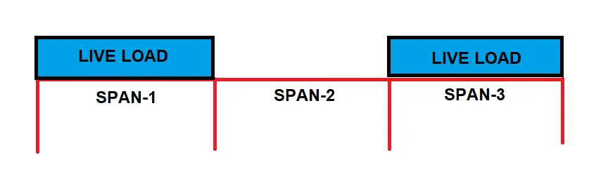
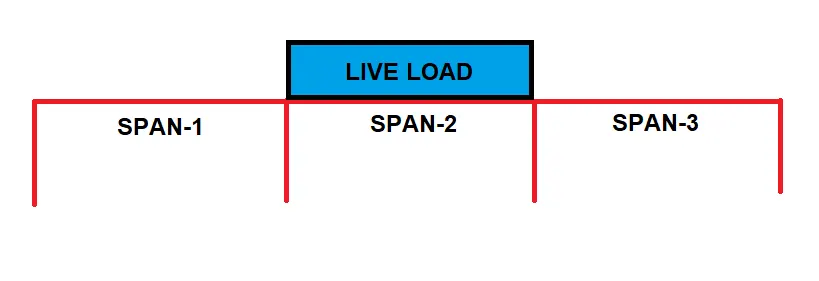
The vehicle (or live loads) must be examined for both continuous and discontinuous situations after all dead load, surfacing, and accessory installation.
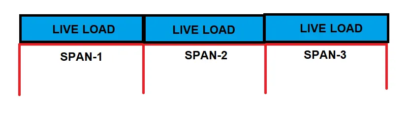
The preferred cases for checking live load as follow,
(a) Odd spans
(b) Even spans
(c) All spans
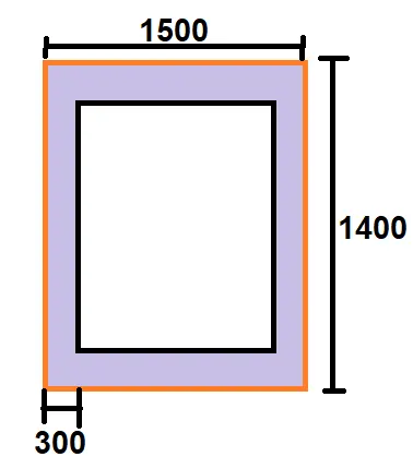
The initial sizing for proposed bridge components:
a) Composite steel plate
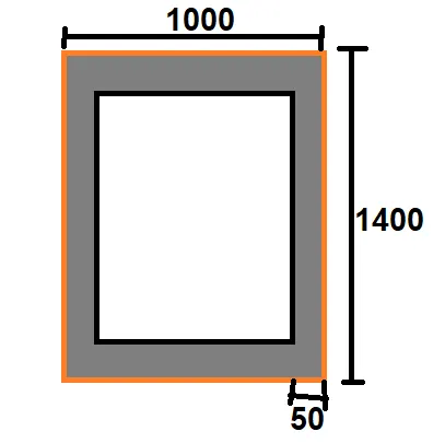
b) Precast Tub wall
300mm thick wall is recommended to place tendon.
Stage-2 and Stage-3 Construction phase:
(i) Precast girders & Steel girders with 20 kn/m fresh deck concrete load
(ii) Bending moment for selfweight+deck concrete load combination:
(iii) Deflection for selfweight+deck concrete load combination:
Stage-4 final construction stage:
(i) full deck slab
(ii) Asphalt loading + curb and barrier loading
(iii) Bending moment due to structure + superdead loads:
(iv) Deflection due to structure + superdead loads:
Stage-5 Live load check:
(i) Live Load All Span
(ii) Live Load Even Span
(iii) Live Load Odd Span
(iv) Envelope for the Maximum and Minimum Live Load Envelope
(v) Factored Bending Moment for Structure +Superdead Load + Live Maximum Hogging:
(vi) Factored Bending Moment for Structure + Superdead Load + Live Maximum Sagging:
(vii) Deflection for Structure + Superdead load + live Maximum Sagging: