Project 2
FINAL PROJECT - 2:
PROJECT NAME : WIRING HARNESS BUNDLE ROUTING ON BACK DOOR :
SOFTWARE : CATIYA V5:
STAGES ON THE PROJECT:
1.PREPARE ALL CONNECTORS & SUPPORT CLAMPS IN ELECTRICALLY.
2.ASSEMBLE THE REQUIRED PLACE AS PER DIMENSION.
3.GEOMETRICAL BUNDLE ROUTING VIA SUPPORT TO CONNECTOR .
4.PREPARE THE FLATTENING.
5.PREPARE THE DRAWING LAYOUT.
PREPARE ALL CONNECTORS & SUPPORT CLAMPS IN ELECTRICALY:
Mandatory settings:
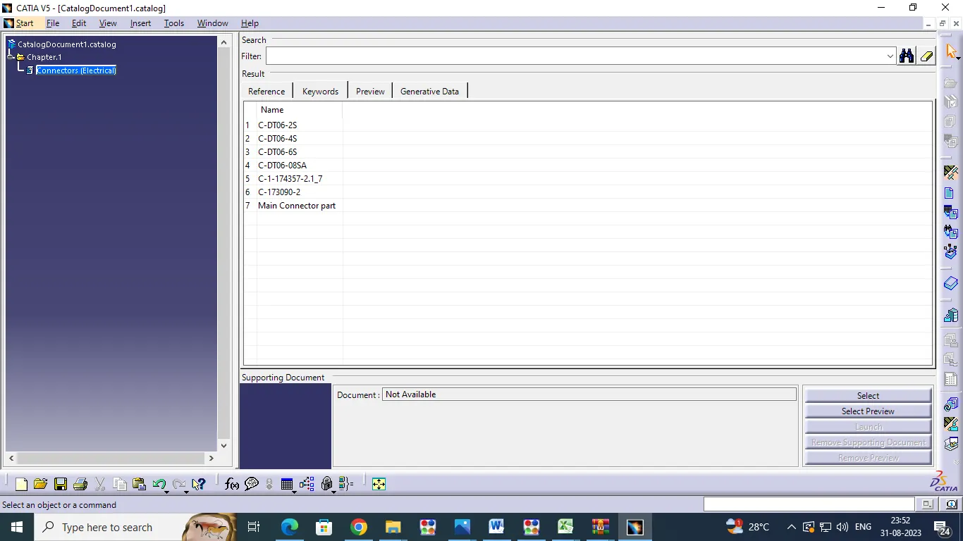
- Before Start the work we are doing modified basic settings and they are go to TOOLS - OPTION and click on Infrstructure pick on Cache management and click on chach activation and cache size and say ok. And go cataloge editor pick on required option then add on standard catalogue file .we want to standard catalogue file go file - new - catalogue document- fix the location and enter name then say ok.The standard catalogue file have created .
- Next move to pick on part inferstructure click the required option then say ok next go to Equipment and system - select electrical mapping and add the connector files.before we want to have create connector catalogue file is same method on standard catalogue file creation.
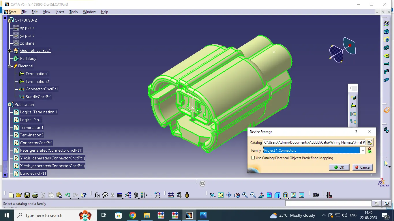
- Download the all required connectors and support clamps to get in TE.COM . Open the website put on connector model number and download the cad file and save. open the connector in part design work bench to creat the point and axis ,then modefiy the what is connector connectivity point ,what is bundle connectivity point and defie cavity and cavity connectivity point also. the process are doing on support clamp but different command like : define support option. before creat support point we have prepare for Entry ,Exit and base plane by using point and plane option in part design work bench. whenever i complete the process i have go to pick store device option and save the connectors ,Clamps ,COT Tubes in catalogue file. Finally the cataogue file is added on electrical mapping option. why we are saved on this option once we were save this next we want this component part easily to got it .
What is Connector ?
Connector is Defind as an Electro Mechanical device which is used to join electrical terminition and create electrical circuits.It is Consists of Housing,Terminal,Lock ,Sealing,Wedges, Cavity,Mounting Cam.
HOW TO CONVERT MECHANICAL CONNECTOR & SUPPORT CLAMP TO ELECTRICALY:
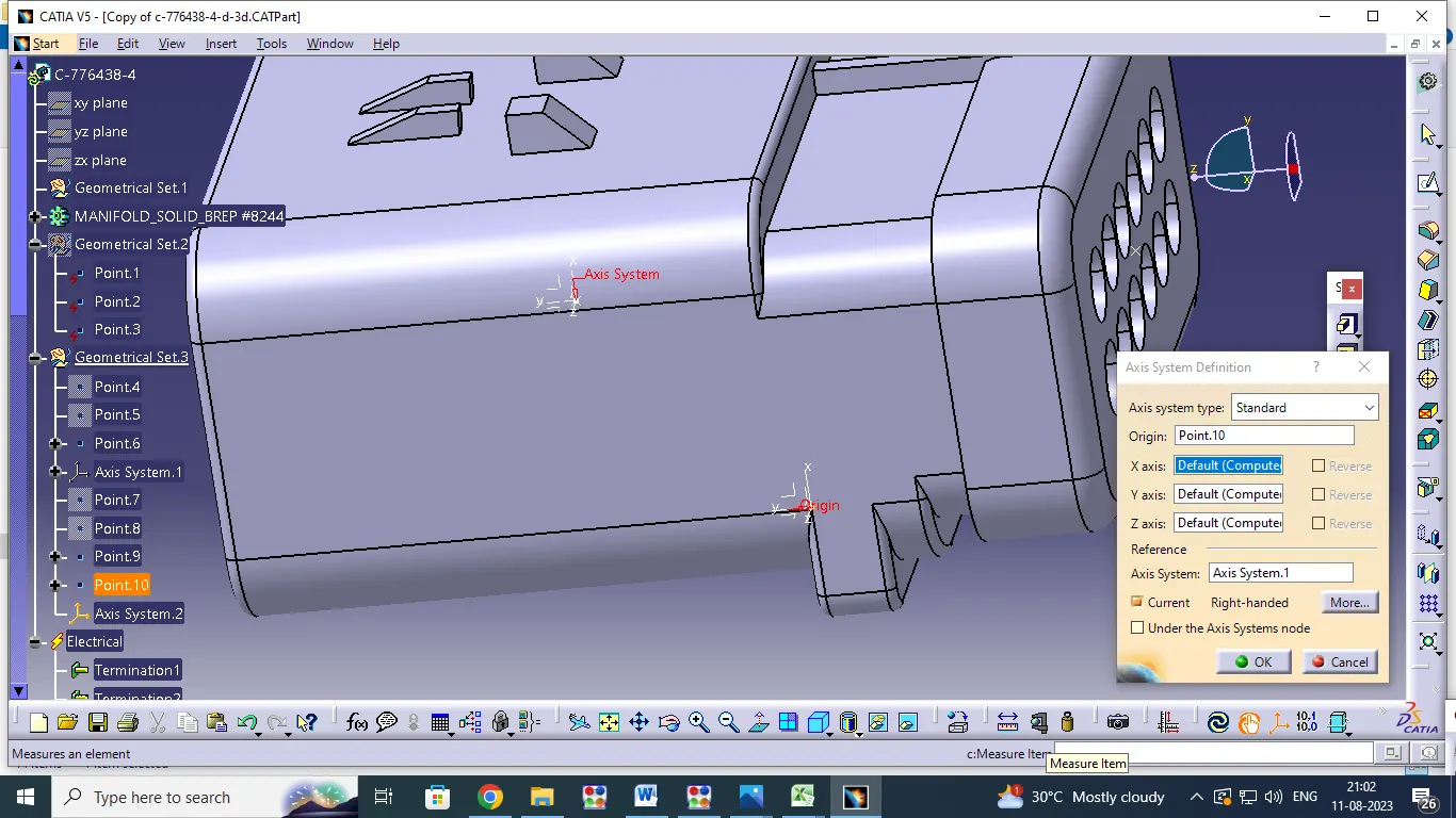
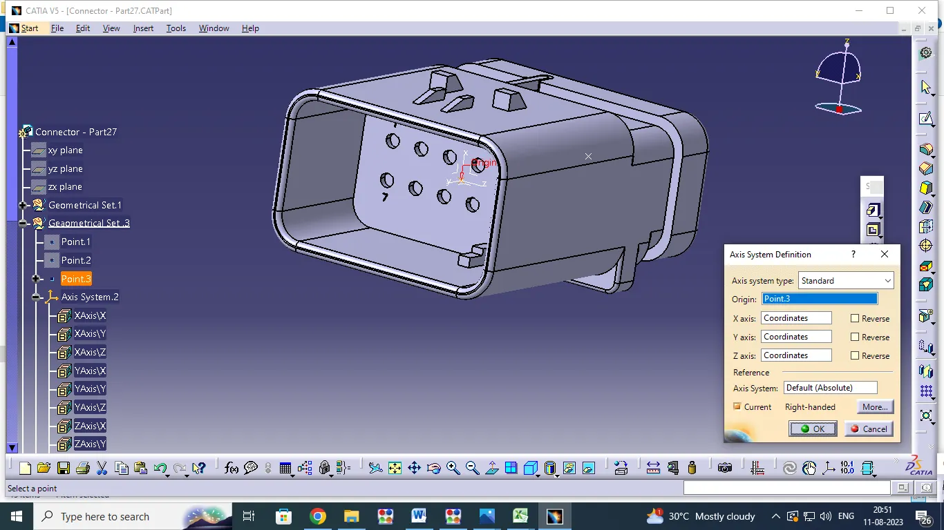
- First of all Download the component on TE.COM and open the part work bench on catia v5 window .Identify the which side is connecter connectivity and bundle connectivity first .then creat the point and axis in which mounting direction. like y axis direction is coinsidence ,z axis is orientation and x axis is side facing.
- I have chose in below type of connectors ( Female ) Modle Like:
LIST OF CONNECTORS USING:
- c-1-174357-2-e-3d
- c-173090-2-a-3d
- Main connector
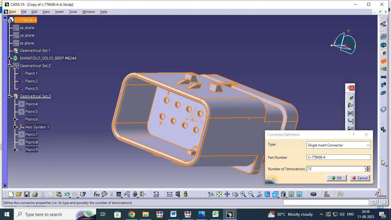
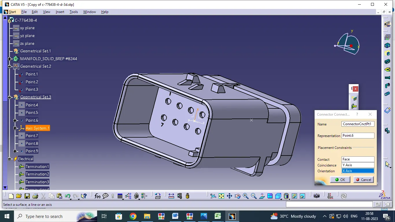
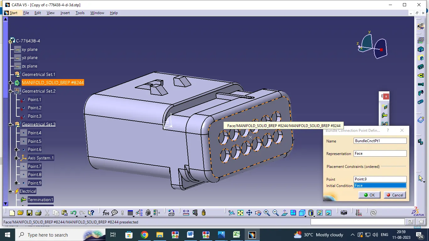
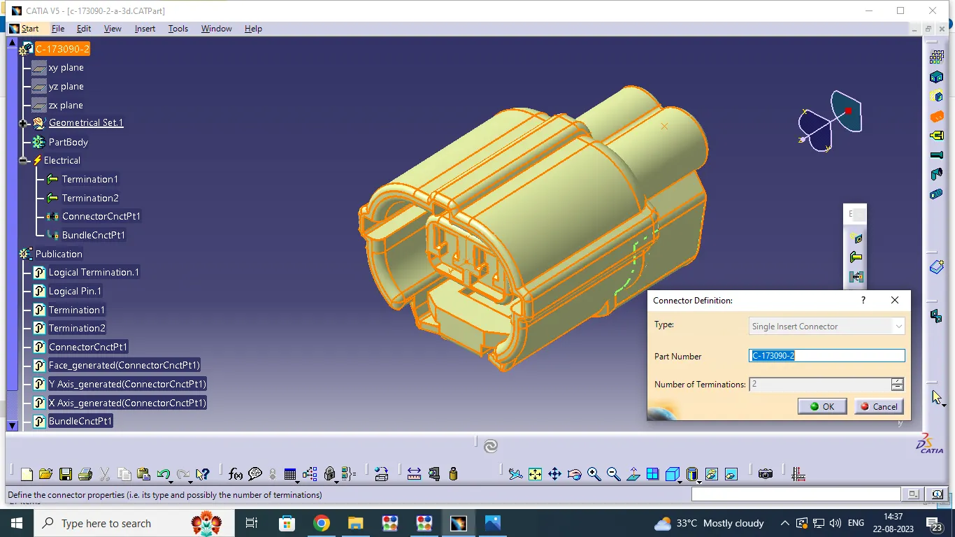
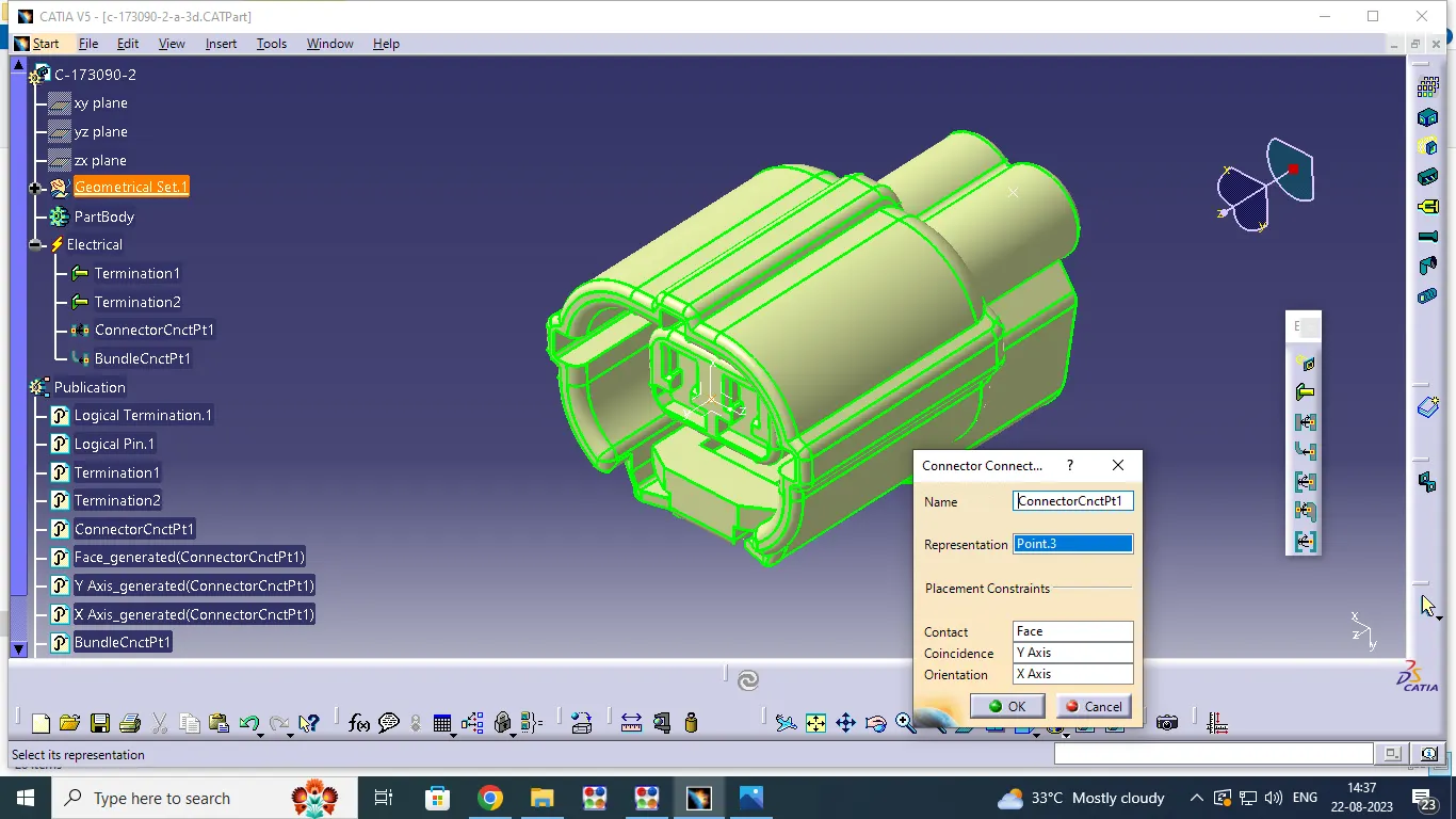
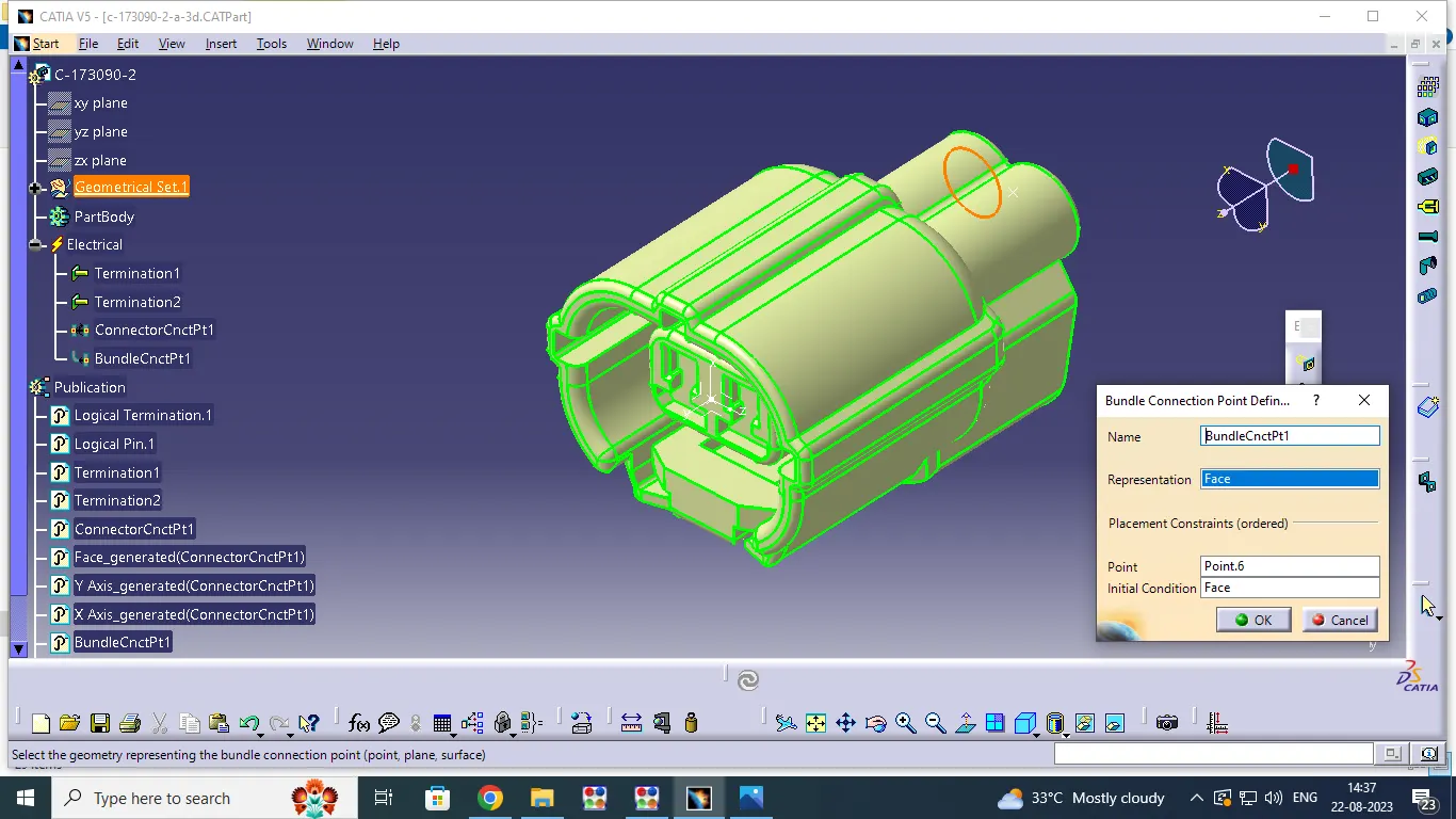
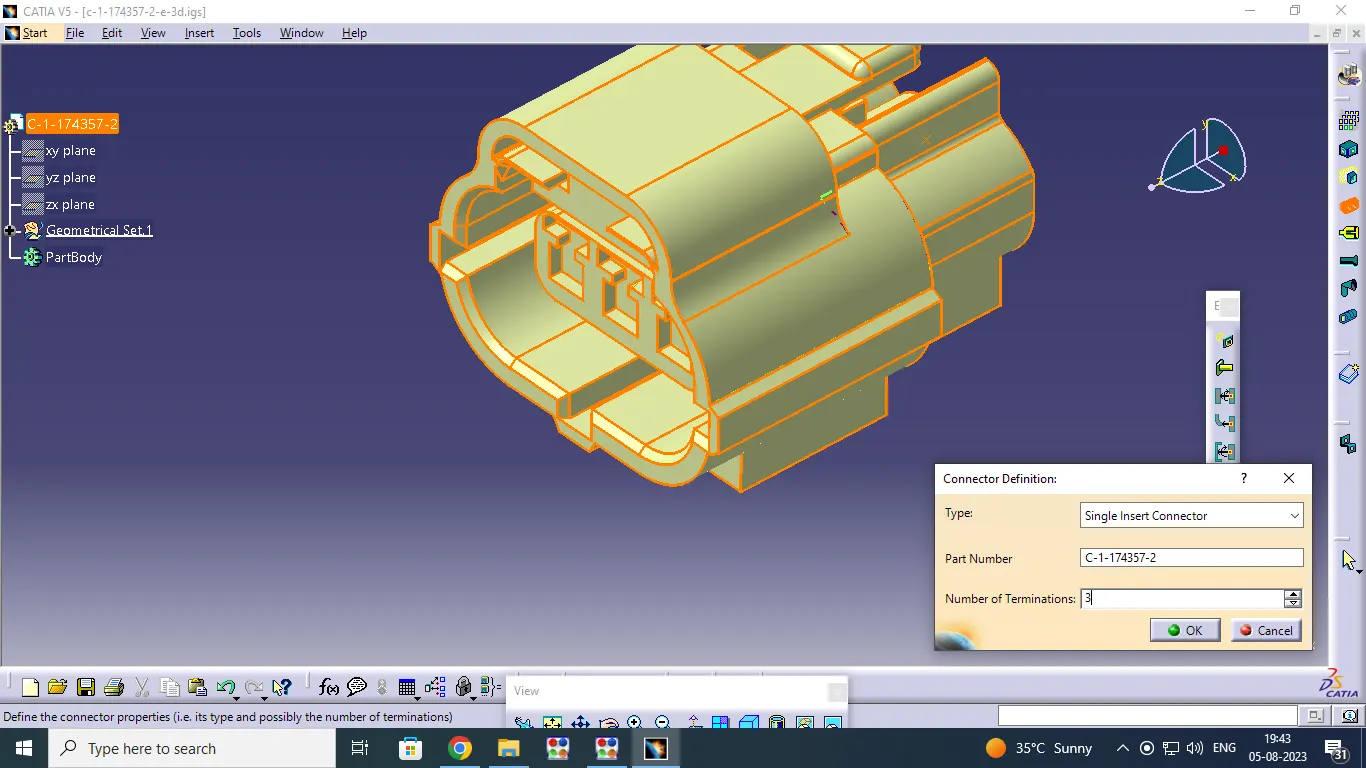
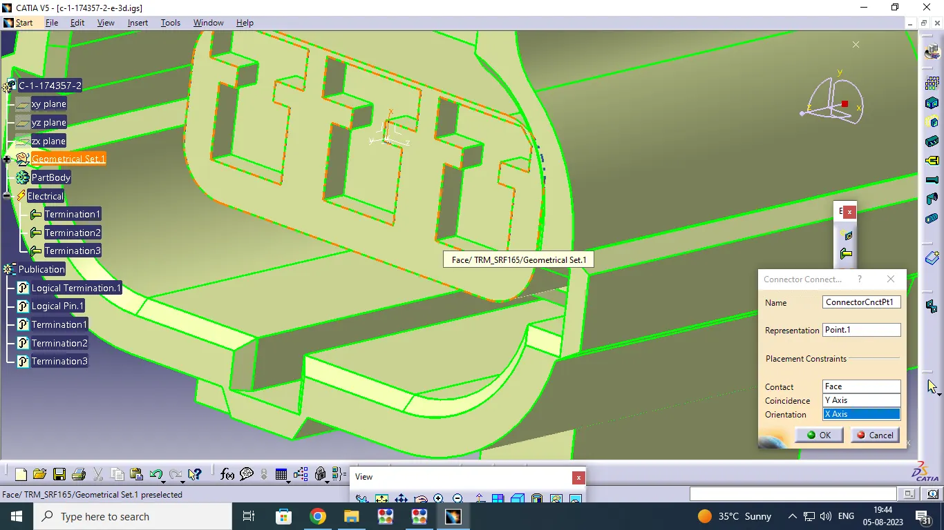
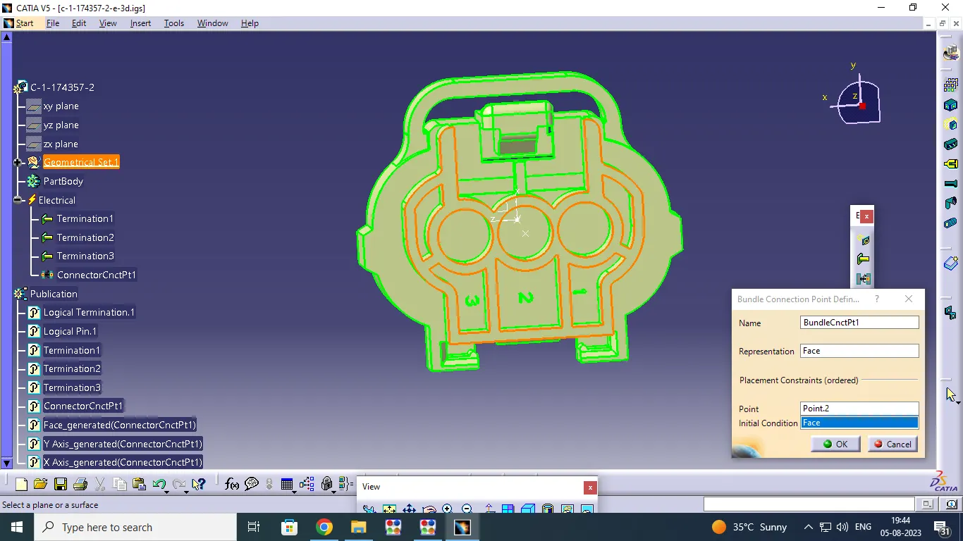
- Select on Define connector option and enter the Type is - single insert connector , Number of terminition - ( how many Terminition in that connector like : 2 - Pole ,3 -Pole ,12 - Pole and click ok. next pick on connector connectivity point and give requied detailes like ,representing point - mid point of Terminition , contact - connector face , y - direction is coinsidence , x - direction is orientation ,z axis is side facing and Click ok .At same time open on Bundle connection point give the representation side - Connector Face ,point - Center point of connector Bundle side , Initial condition - Connector Face and say ok. Finally we have to creact on Define cavity and cavity connection point and it same process like Bundle connector point .the deatils are representation side - face ,point - mid point on that surface ,Initial condition - connector face .
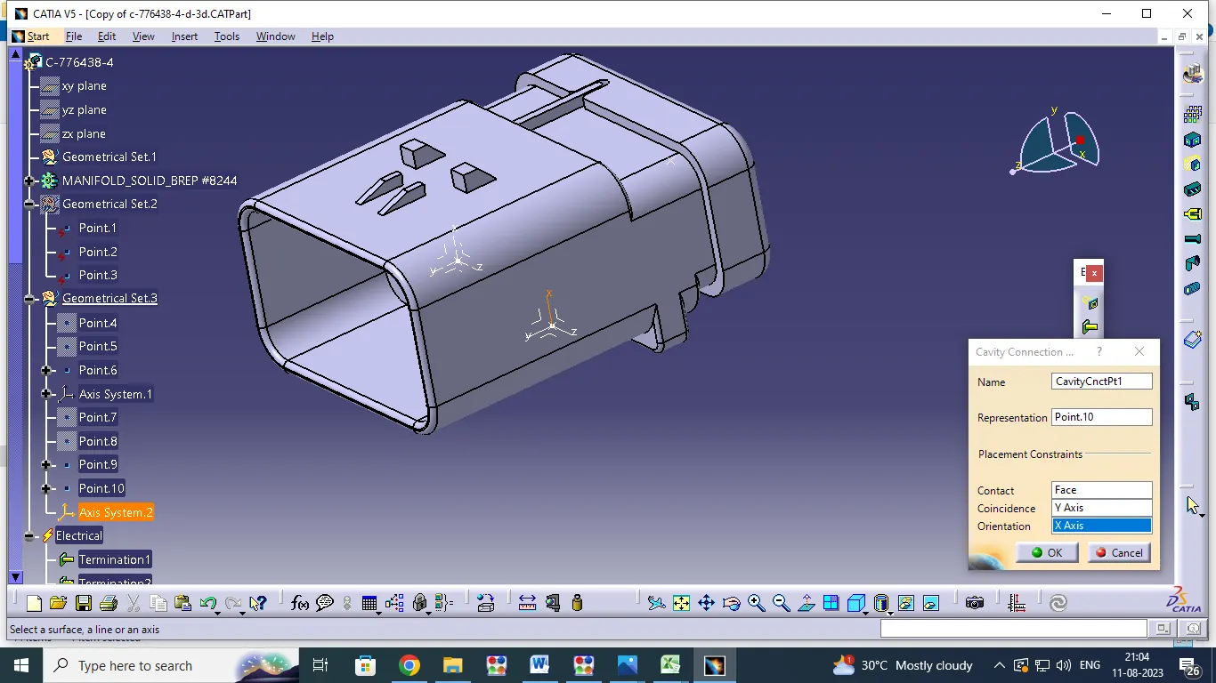
- This Component are designed by connect to the connector by using define cavity option . pick on cavity connection point and give requied detailes like ,representing point is mid on Axis point ,contact is mounting face , y - direction - coinsidence its mounting direction , X - direction Is oriendation z direction is side face and say ok ,at same time open on Bundle connection point give the representation side - face ,point ,Initial condition - face and say ok.its is cavity connection point creation.
- Open on Assemble Design (product ) Work bench window copy the electrical component design parts like connector head male /female and cavity clip past the product window then change the electrical assembly workbench select the connect electrical device option and pick on the cavity clip and connector head point and same process doing on male and female connector devices.
CONNECTOR SPECIFICATION:
1. Electrical Connection Poles.
2. Operating Current /Wire Gauge
3. Packaging Space Constrain.
4. Availabe Size.
5. Operating Temperature.
6. Sealing Requirement
7. Available Standard(Automotive/Agricultural/MIL Grade)
8.Secondary Locking
SELECTION PARAMETERS OF CONNECTORS:
-
Electrical Connection Poles.( Number of Pole)
-
Operating Current Circuit /Wire Gaug
-
Packaging Space Constrain.
-
Availabe Size.
-
Operating Temperature.
-
Sealing Requirement
-
Available Standard(Automotive/Agricultural/MIL Grade)
-
Project Cost
-
Secondary Locking requirement
Connectors Supplier:
- Tyco Electricals
- DEUTSCH Connectors
- Molex
- Amphenol
- APTIV
- Delphi
- YAZAKI
- Sumitomo
- JST
- Furukuwa Electrical Group
- LEAR
-
SUPPORT CLAMP:
- Support clamp is one of the Supporting Component for Electrical Wiring Harness.Its Support for Cables and electrical Components.Verious Support Clips are there in the system,they are,
1. P Clamp
2. Furr Tree Clip
-
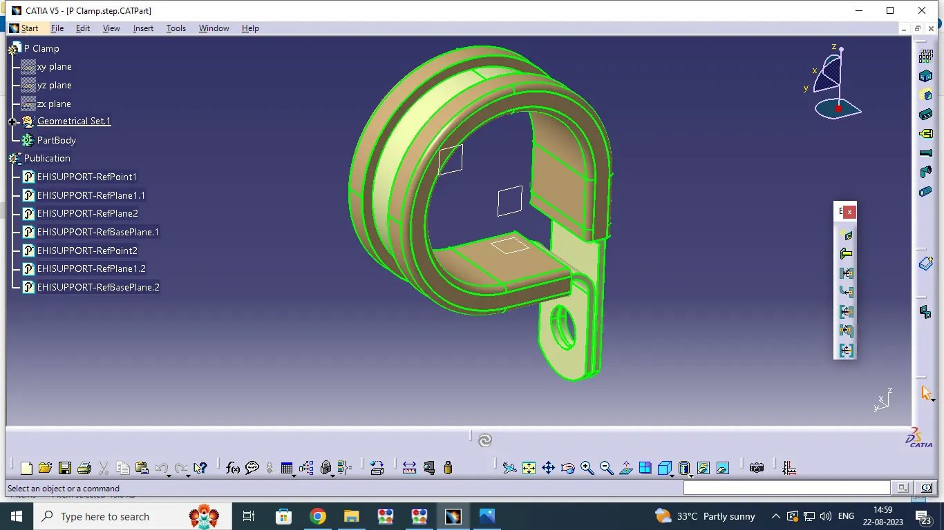
- Download the cadfile for support clamp in TE.COM,YAZAKI etc ans open the file in CATIA V5 Part workbench .Then Open the file first identify the whish side is Entry point ,Exit Point and base in clamp component.How to identify the Entry, Exit and base are clamp.Cable routing entry side is entry point of the clamp , Cable exit side exit point of the component,then inbetween of the entry and exit sides at same time the cable bottom will touch on clamp that side is base point or plane of clamp. whenever we have maintain minimum 2 mm gap in base plane on the support clamp
- And the we have choose on Point & plane tools its create the point & plane on the entry,exit & base side.Select the piont option , create the point in middle of the entry side .next create point on middle of the exit side.then select plane tool creat the plane in entry side center of the pont by use offset from plane method.The same process doing on the extit side also .finally base plane create the base side on calmp.
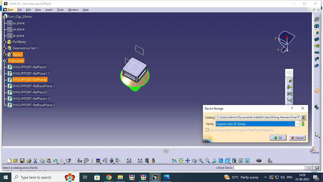
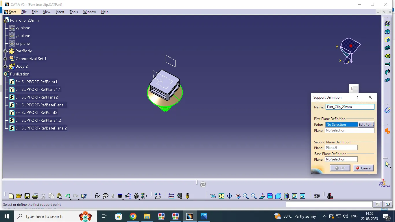
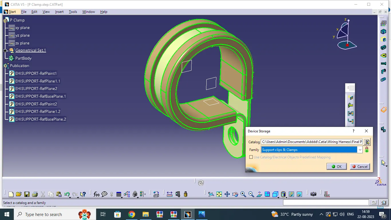
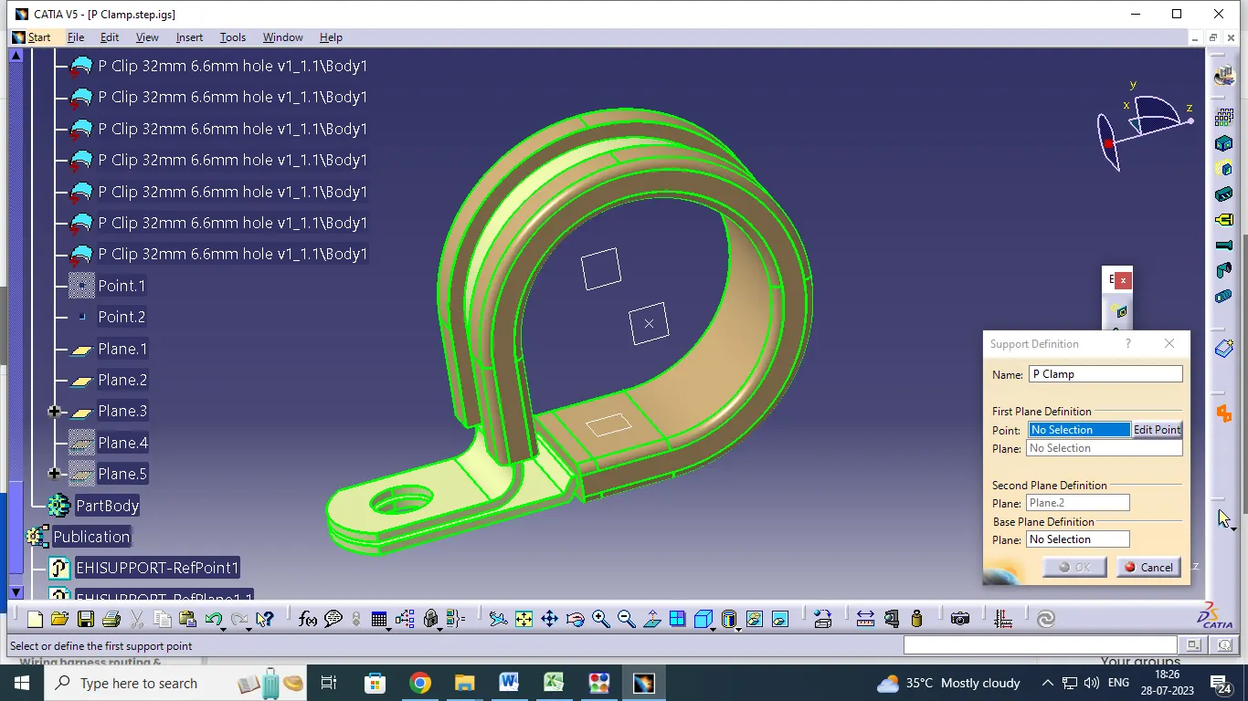
- After completing the point and plane creation go change on workbench is electrical part design.select on define support part tool and pick on the p clamp .open the window give the some details like first point & plane , second plane ,base plane and say ok . next again pick on option give detailes for first point and plane ,second plane is here in default then base plane and say ok, the component have ready for electrical wiring harness assembly work bench.finally save on new catalogue by using storage device option.
CORRUGATED TUBES:
Corrugated tubes are Protect for wiring cables prevent for any other enviromental causes,heavy heat temperature and other causes.its made by two type of materials.
1.PVC Corrugated tube.
2.Cotton /Polemer Made Corrugated tube etc.
PVC Materials is basically plastic material its like ,poly viniel cloried (PVC ) Cotton tube is made by polemer material its high heat resistence compare to PVC Corrugated tubes.
PROTECTION DEVICE SPECIFICATION:
1. Temperature Resistance.
2. Internal Diameter
3. Outer Diameter
4. Absorpation Resistance
5. Resistance to Hazardous Liquieds
6. Resistance to Hazardous Gases
7. Resistance to flams
8. Color
9. Types (Slit or Non- Slit)
10. Material-( PVC , PP,Cotton,Silica,Woolen/Breading)
SELECTION PARAMETERS OF PROTECTION DEVICES:
1. Temperature Resistance /range
2. Size/Diameter
3. Type of protection device( Based on Requirement)
4. Abrasion resistance requirements
5. Color Requirements
6. Cost Consiterations
Wire Supplier:
- Tyco Electrical
- Schlemmer
- Panduit
- Yazaki
- LEONI
- Sumitomo
15mm COT:
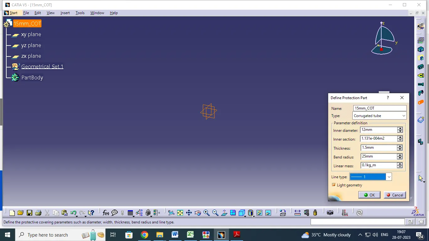
- corrugated tube creation is doing on electrical part design workbench first open on new part workbench then change to electrical part design workbench then go to click define protection part option and click part body on Geometry tree structure .
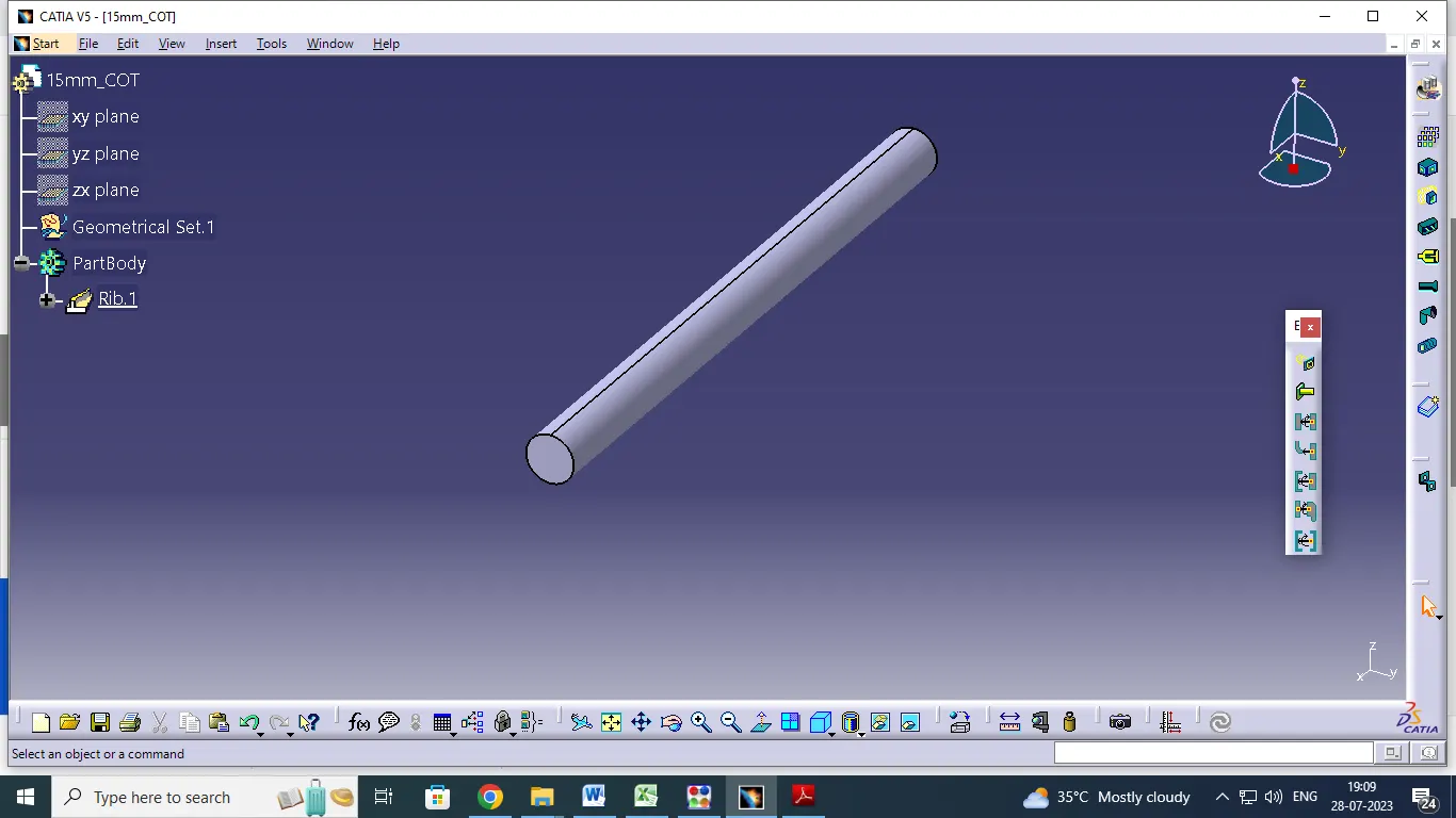
- The option will be open and give required values like : Name ,Type - Corrugated tube , Inner diameter - 12mm ,Inner section is Creat automaticaly depensupon the inner diameter values ,Thickness - 1.5mm,Bend radius - 25mm ,Linear mass - 0.1 kg and line type - straight line symbol and say ok.The covering tube would be creat and then go to save.
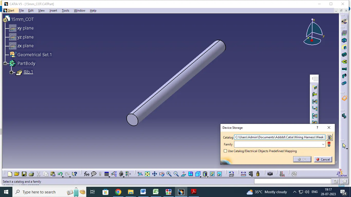
- Next the part will be add on storage device .if you add family first we want catalogue document.so create the catalogue document by using File - new - click catalogue document option the catalogue window open and give name and select which type we want to save ex : conduit , then say ok. next pick add part familly option open window default name and select which type of part then say ok .
- finally open the electrical part design work bench select device storage tool click on add familly go to folder location pick on catalogue document file and say ok. then come to storage device select familly and say ok .the part have been saved on catalogue document
10mm COT:
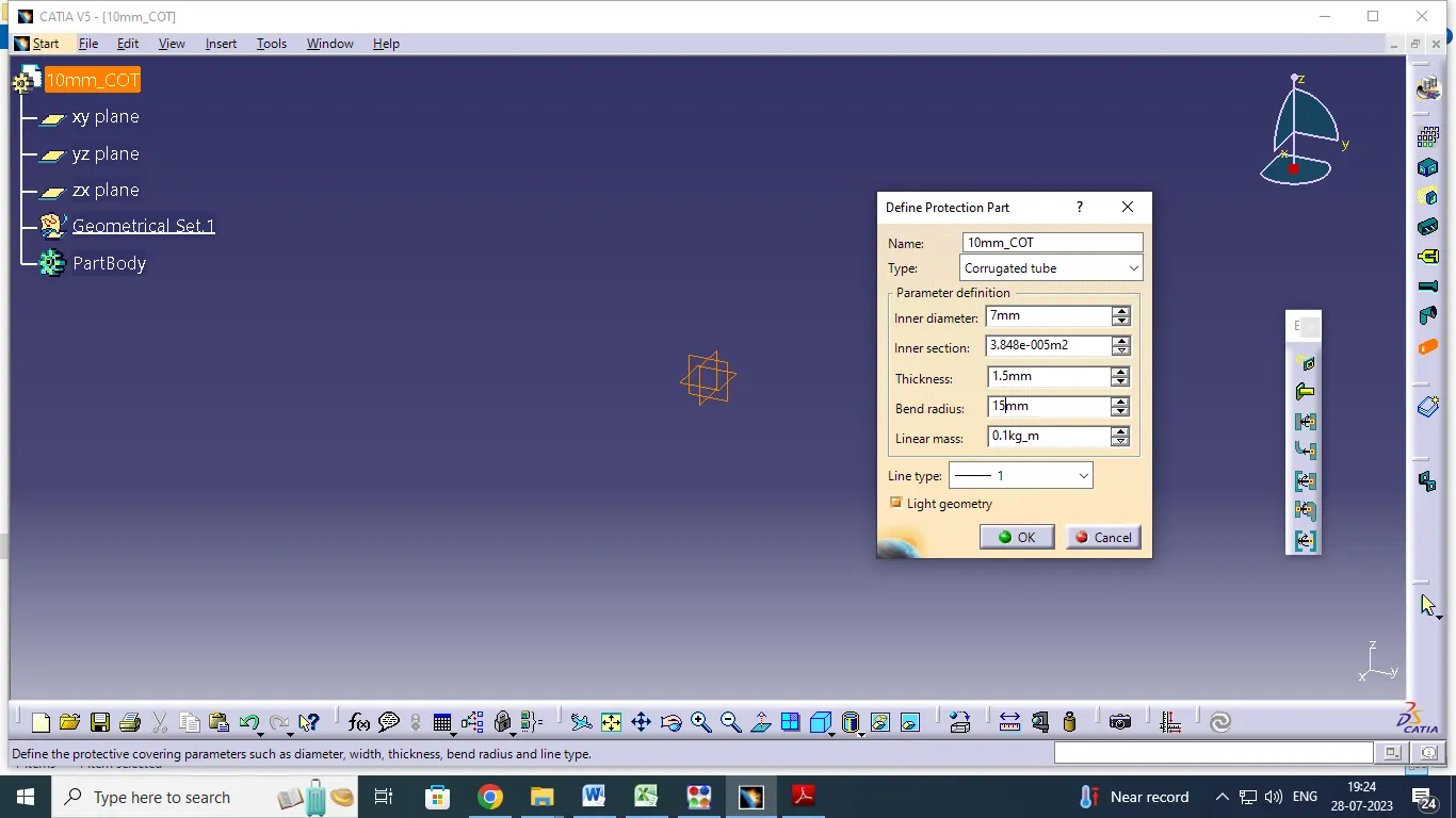
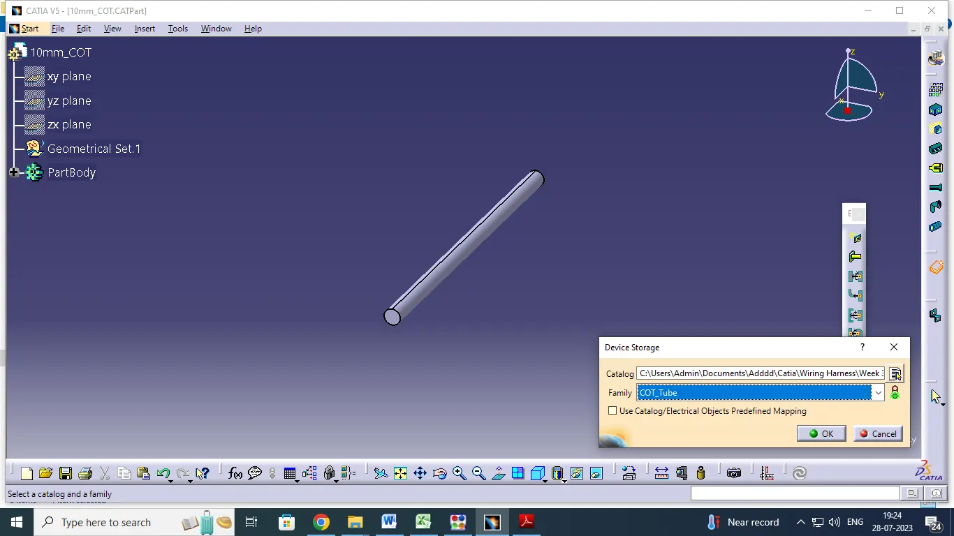
- Select electrical part design workbench first open on new part workbench then change to electrical part design workbench then go to click define protection part option and click part body on Geometry tree structure .
- The option will be open and give required values like : Name ,Type - Corrugated tube , Inner diameter - 7mm ,Inner section is Creat automaticaly depensupon the inner diameter values ,Thickness - 1.5mm,Bend radius - 15mm ,Linear mass - 0.1 kg and line type - straight line symbol and say ok.The covering tube would be creat and then go to save.
20 mm COT:
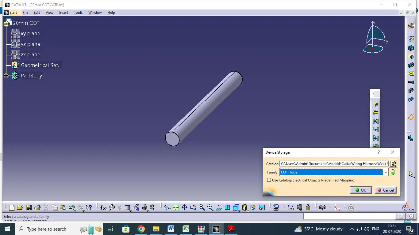
- The option will be open and give required values like : Name ,Type - Corrugated tube , Inner diameter - 17 mm ,Inner section is Creat automaticaly depensupon the inner diameter values ,Thickness - 1.5 mm,Bend radius - 30 mm ,Linear mass - 0.1 kg and line type - straight line symbol and say ok.The covering tube would be creat and then go to save.
CATAOLOGUE DOCUMENT CREATION:
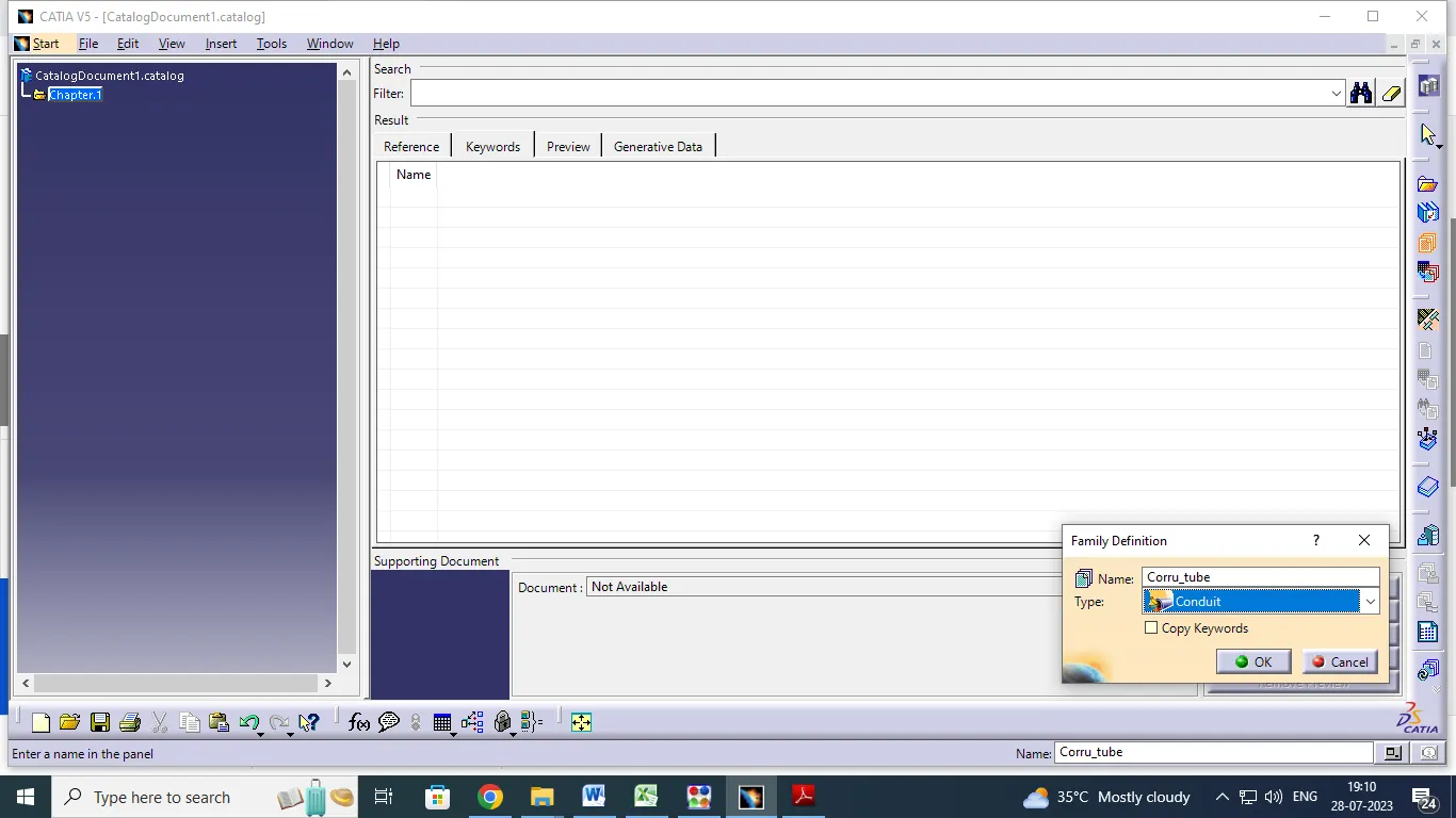
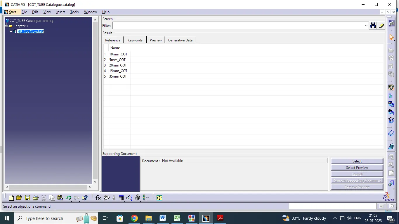
- Next the COT Tube will be add on storage device .if you add family first we want catalogue document.so create the catalogue document by using File - new - click catalogue document option open the window click on Add family option open on small window . thwe window ask for name - SLIT_COT and select which type we want to save ex : conduit , then say ok. next pick add part familly option open window default name and Type -Conduit then Click ok .
- finally open the electrical part design work bench select device storage tool click on add familly go to folder location ,pick on catalogue document file and say ok.next come to storage device window select family SLIT_COT and say ok the part will have been saved on catalogue document.
2.ASSEMBLE THE REQUIRED PLACE AS PER DIMENSION.
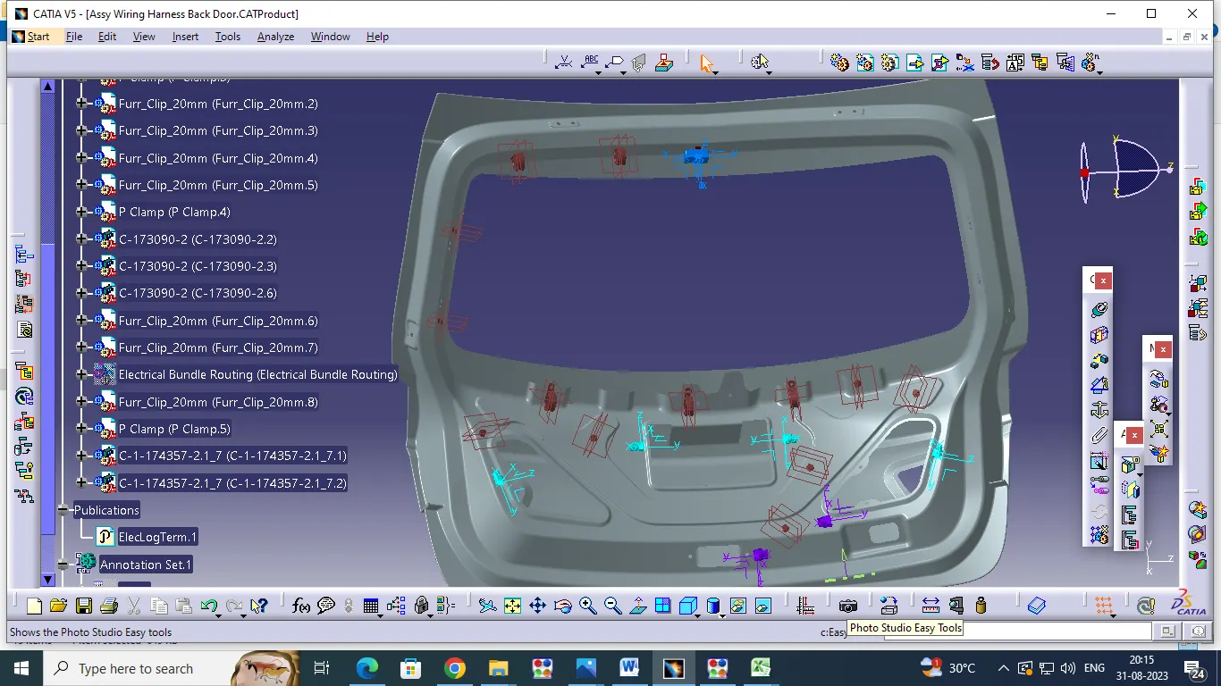
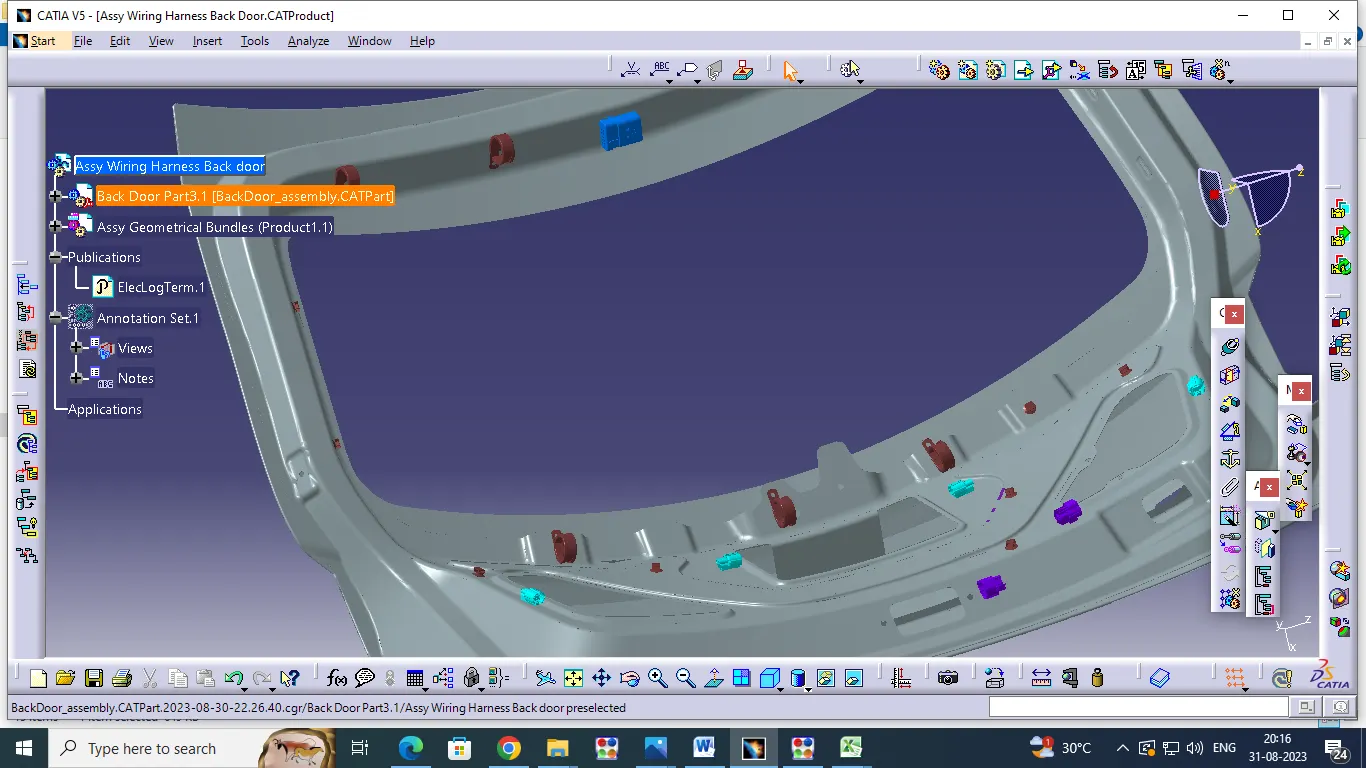
- Open the New Product window in CATIYA V5 give the name for Assy_Wiring Harness Back Door in wiring Harness Product .Then creat the new Product like right click Select the Product 2.1 object pick on New window and option Give the name of Geometrical Bundle 2 .next we have creat another sub product, like: Electrical_Bundle _Circuit. we have doing same process,give the product name for : Geometrical Bundle 1 - Multi Branchable 1
- So start the Assemble process go to pick on Geometrical Bundle 2 product option and then select new component option go to the location select and open on all required connectors , clamps, and Guiding Channels also.then Assemble for the all connectors (Female ) ,p clamps, Furr tree clips, Cavity Clip are fixing the required location on as per wiring harness Techanical terms by using assemble option like ,ex ( manupulation,rotation,snap & compas command ).
3.GEOMETRICAL BUNDLE ROUTING VIA SUPPORT TO CONNECTOR .
WIRE:
- Wiring Harness consist og various wire bundle together,with each indivudual wire responisiable for carrying the electrical signals and energy used in starting the engine ,lights,meters,Navigation systems ,Power unitsdown and doors and others devices in the vehicle.
Wire Specification:
- Standard/Grade
- Current carring capacity
- Resistance per meter
- insulation type/Materia;
- Color of wire
- Temperature Rating
Wire Parameters:
- Wire Current Capacity(Laod,Resistance requirement)
- Wire type/Insulation
- Color of wire
- Operating Temperature
- Flexability Requirement
Wire Supplier:
- Tyco Electrical
- LEONI
- YAZAKI
- POLYCAB
- FINOLEX
- MOLEX
- APTIV
A. WHAT IS HARNESS ROUTING ?
Harness routing is basically shows that path of wiring harness into the vehicle.It is represent of the layout of the wiring harness as vehicle in geometrical way 3D .
B. WHAT IS HARNESS PACKAGING ?
It is involves that desicion of Harness mounting in routing management.Also deals with clearence management,Aesthetic management,thermal management,Manafacturability (Like , clip clamp,guiding channel)
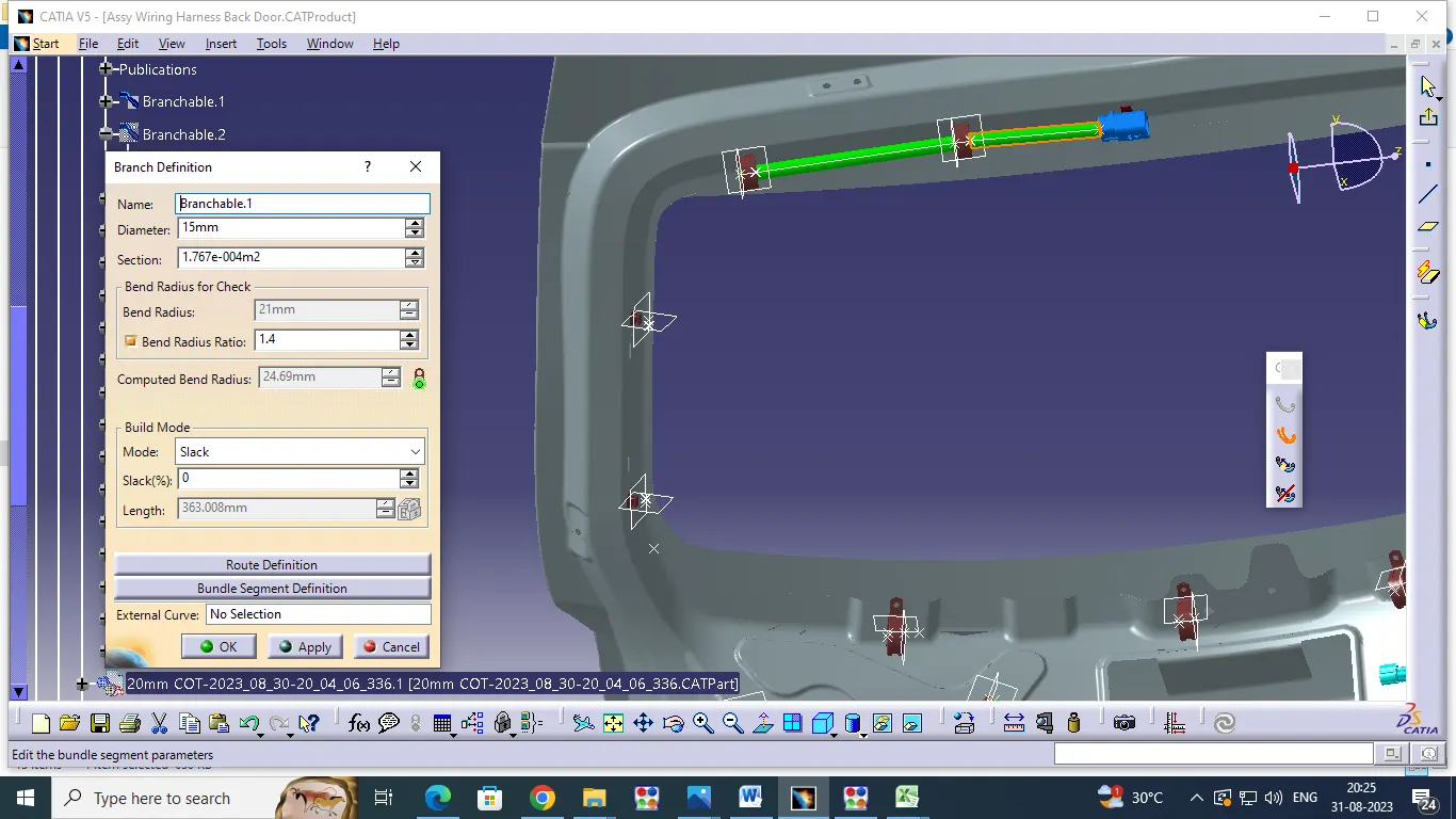
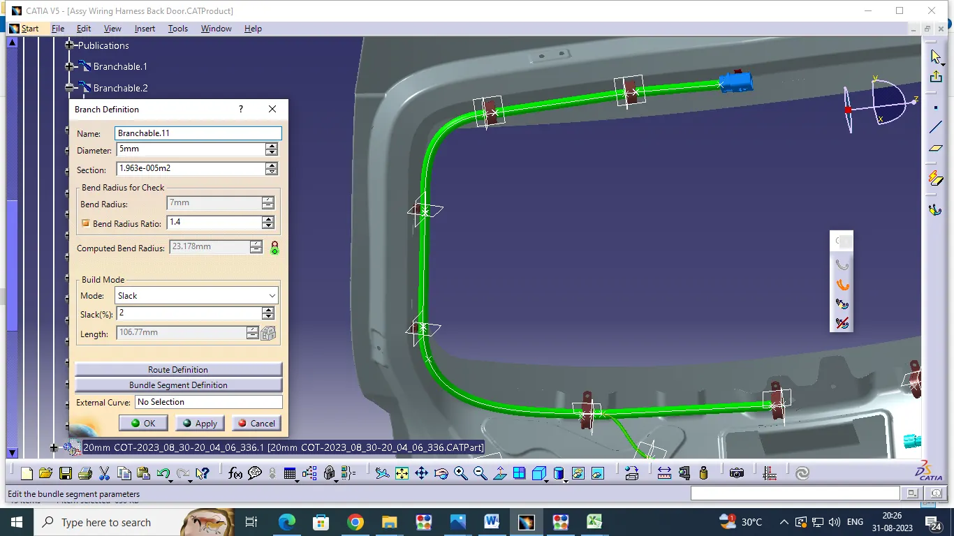
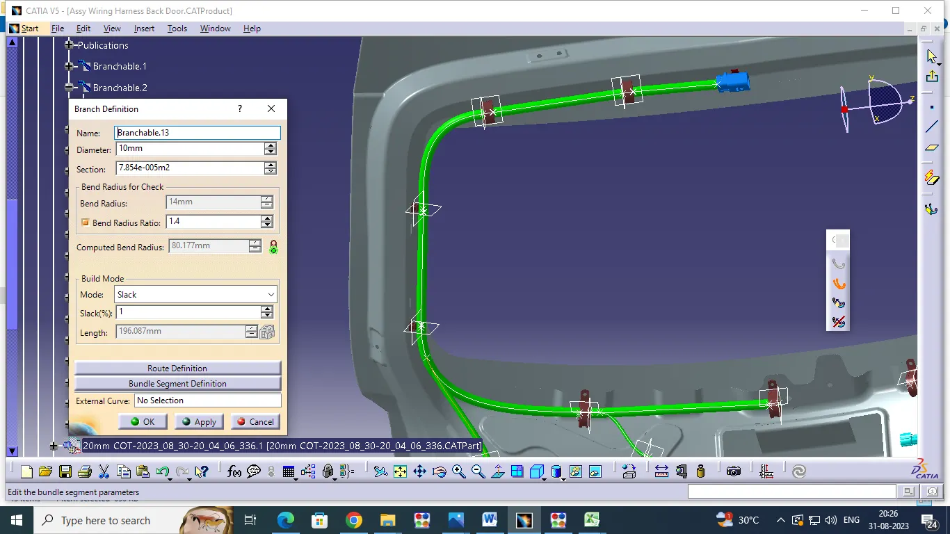
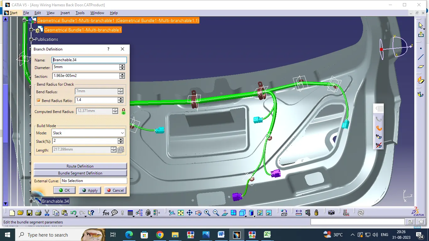
- The assemble area clearence , like connector & support clamps fixing length & Angle dimensions are as per techanical terms ,when will complete the assemble process then start for routing process.First change the electrical Harness assembley workbench and ensure thet you have your harness geometrical bundle id highlighted.select icon on electrical Harness assembley and pick on product :Assy_Wiring Harness Back Door .next we have select the Muiti branch option creat and add the another sub product in Assy_Wiring Harness Back Door .The sub product name is Geometrical Bundle 1 - Multi Branchable 1 then select the branch definition window box input all required values like :name : Branchable .1 , Daimeter : 15 mm (this is main trunk branch routing diameter )and We have additional sub branches are routing in this challange.they are 10mm Dia & 5mm Dia. Section: 1:13Ie-004m2 (its automatically created),Bend radius : 14mm,Bend radius ratio : 1.4 and mode : slack ,I have the routing the cable in Required clearence so i give slake valve for 2mm,5mm,8mm,10mm,15mm
- We are routing branch definitely should maintained the branch to branch distance - 50mm Minimum and the Branch to connector distance 50 mm Minimum.
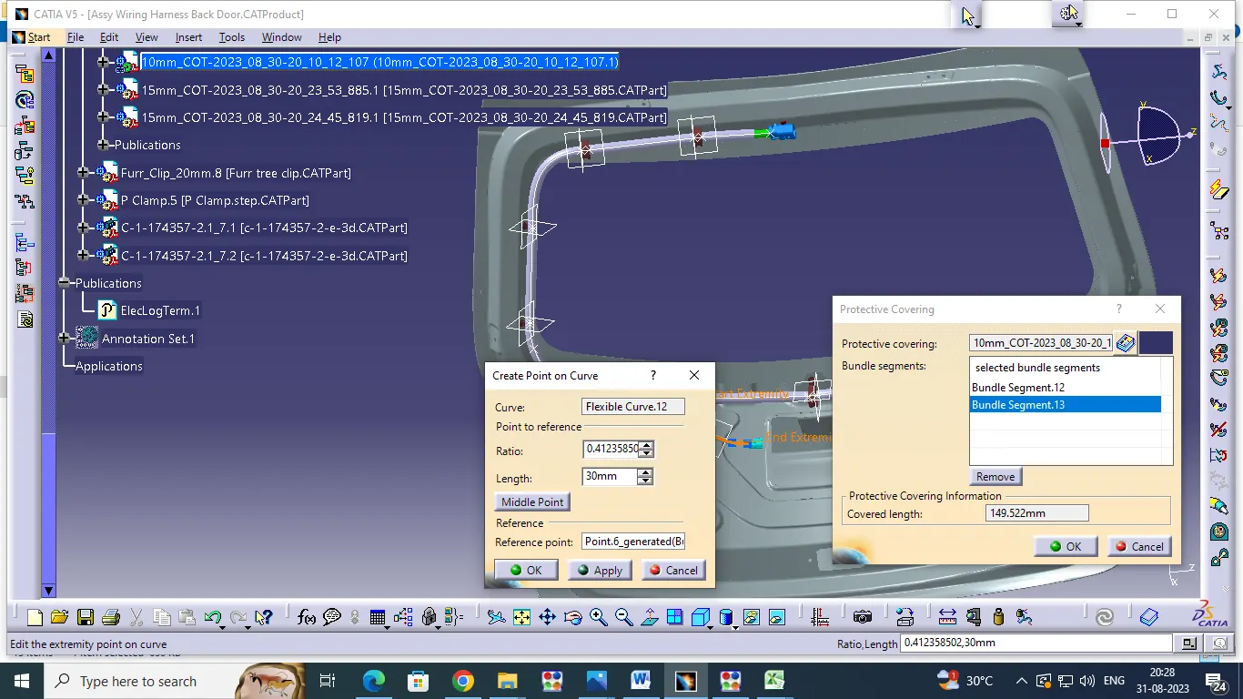
- After the input values click on Routing Definition Option, Select one end connector Bundle connectivity point side and change or ensure bundle direction by using reverse tangent option and ensure the Add After option are highlighted , select the p clamp entry side the cable have routed successfully next pick on p clamp entry side and through Furr Tree Clip then go to pick another connector bundle connector point side after full main trunk routing is complete add branch point option .select this option open on the window select refernce point give length valve from referance point for clearence purpose say.The brance point will be created as per required clearence .then same process is doing on the create branch routing.
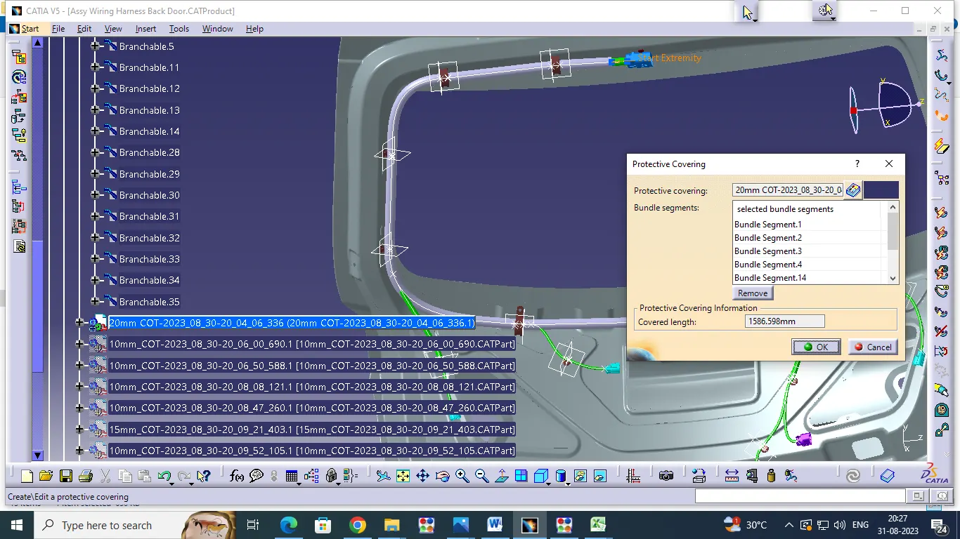
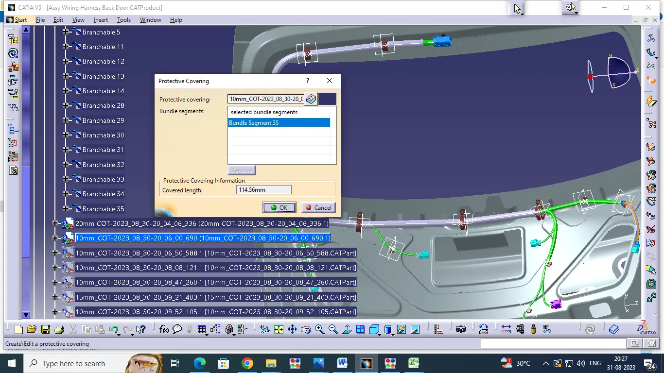
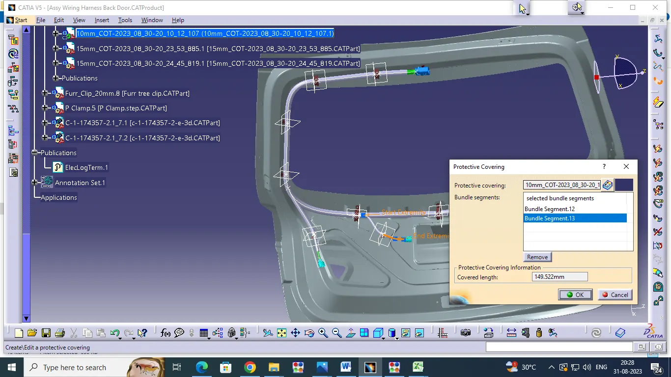
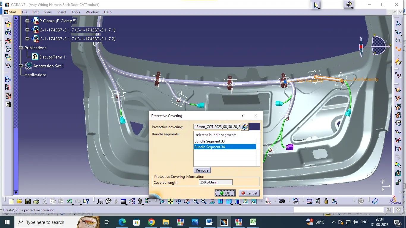
- Finally Carrougted tube is most importent think on the cable routing process.complete the wiring harness extie the multi branch option pick on define protection option in before select rougting cable .After the click the option the cataloge document window will be open and select which type of size we want and say the corrugated tube have applyed on the roughting cable.We have choose for Size : 20mm , 10mm, 15mm Like that .
4.PREPARE THE FLATTENING.
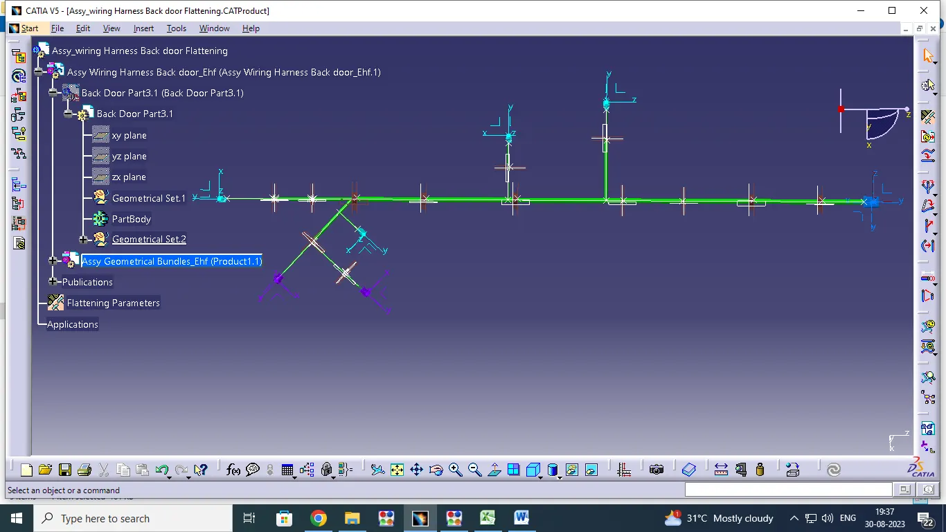
- Open the new product give the name of Like: Assy_Wiring Harness Back Door and change the work bench in Electrical Harness Flattening,Before entry the flattening Workbench we have change some settings,they are Start - Electrical & Equipment - Electrical Harness Decipline - Electrical Wiring harness Flattening open the window click new formOption and say ok.Then go to the Assembly Work bench Change the settings ,they are TOOLS- OPTION-Open the Harness Flattening Parameter window - click Genreal and pick the required option and say ok then save .
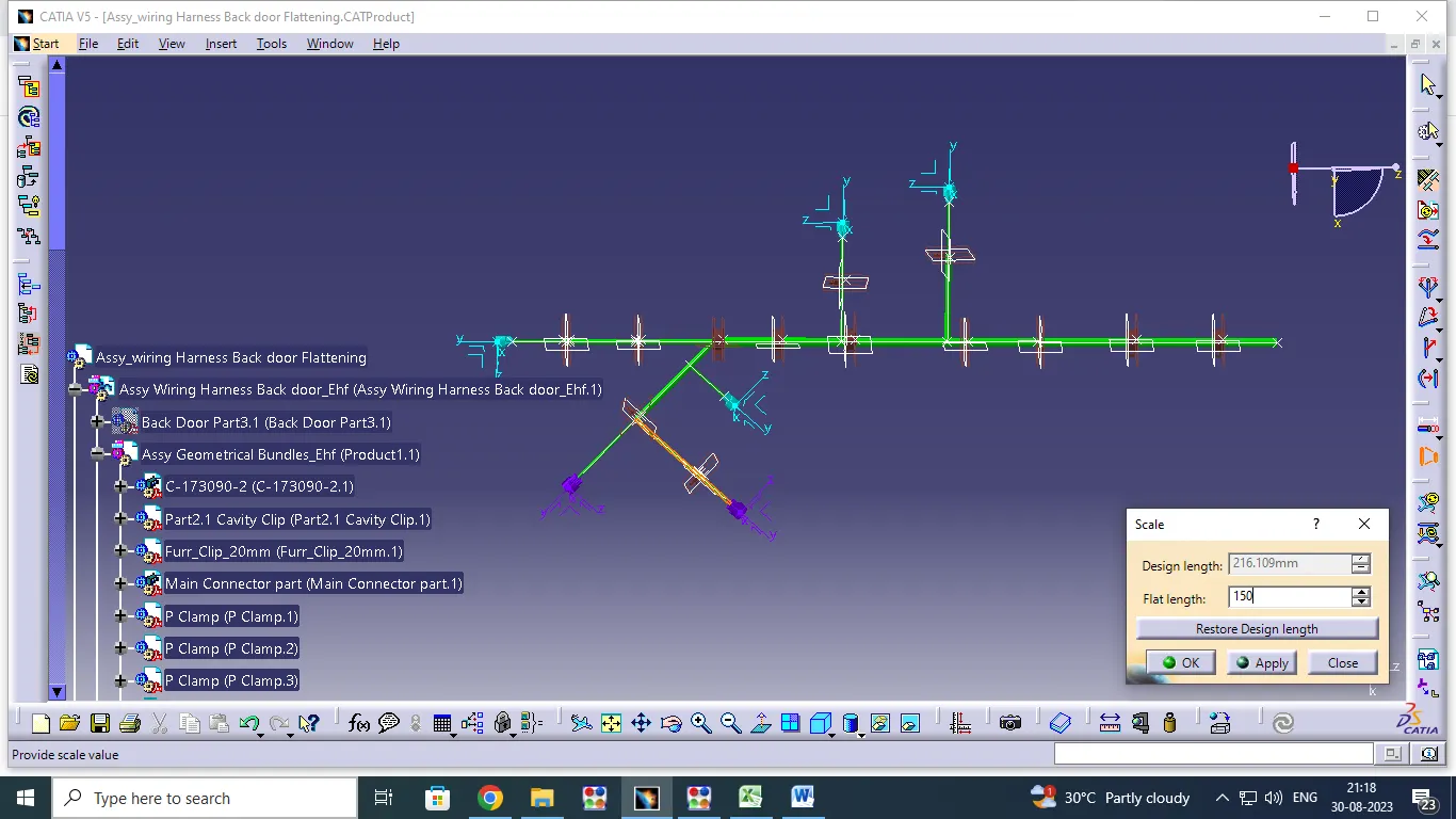
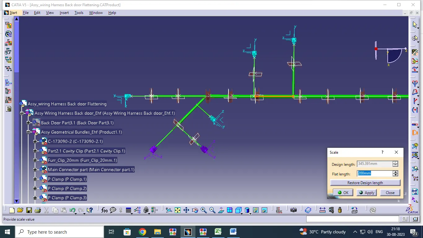
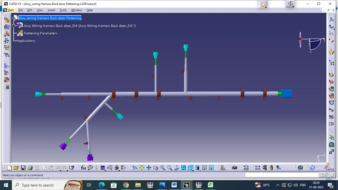
- Creat the flattening workbench select the wiring_Harness Flattening Parameter option and select the required parameters like:For bundle segment - Single line ,For Device - 2D Detailes and say ok the commend will join the geometrical tree structure.next pick on page option and select the wiring harness assembly the assembly will copy and past the flattening work bench and click the update .then we have choose the flattening option,select the connector face and select the all branches and say ok then the Wiring harness assembly would be flattening.Next we have choose the rotation command and select the wiring branch give angle Size : 45 Deg and ok the branch would be changed.The scaling option is also doing in the flattening click the scale command and pick on some one routing branch and give the length value Like : 150mm and ok the wiring harness routing length would be modified.Finally we have doing on Synchronize.sychronize is if any protection covering fix on wiring Harness assembly at same time we want flattening Assembly also covered.Select the sychronize option and show the window then all option are there in the window if we have dont change on the option and say ok.Finally the Carroughted tube also covered in the Flattening Assembly.
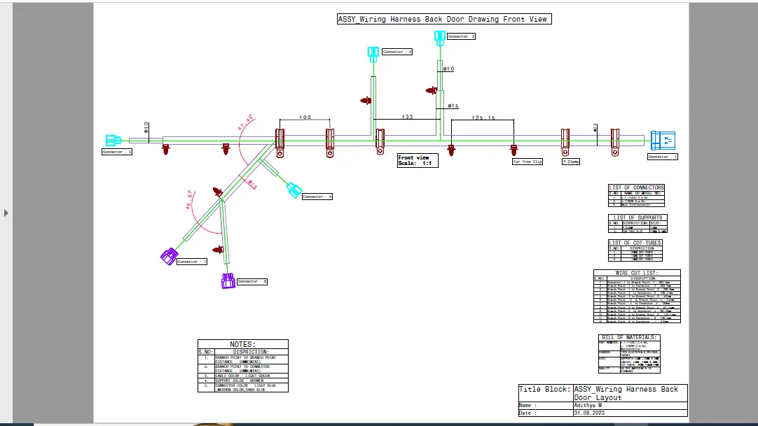
5.PREPARE THE FLATTENING DRAWING LAYOUT.( DRAWING WORK BENCH ):
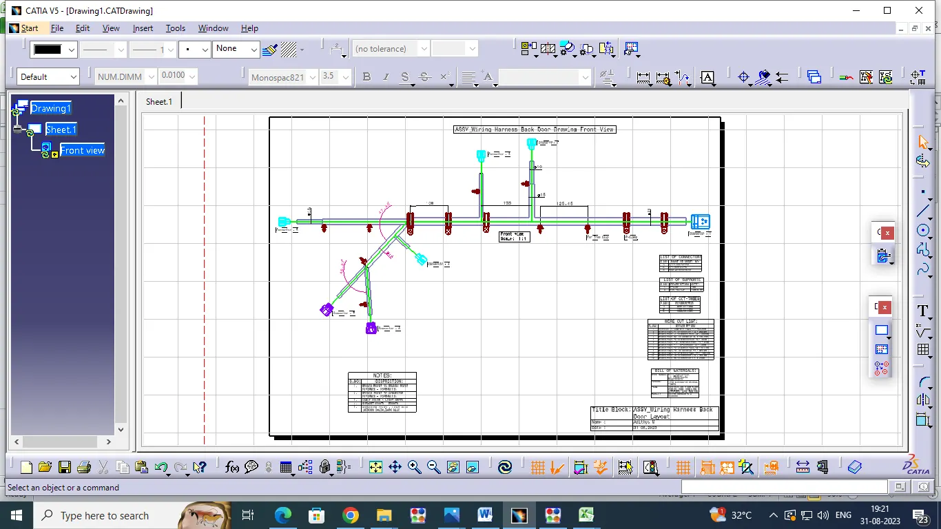
- Drawing Work bench is open when i Click the File - new - Drawing,then the drawing work bench will be open. before some setting will be change like :For bundle segment - Single line ,For Device - 3D Projection and say ok.Now pick front view option and select the Assembly wiring Harness Work bench and pick on drawing workbench only the component have visiable the routing did not visiable.so right click - properties- open the window - pick view Select Always 3d wireframe and select is always visiable then the wiring harness routing also visiable. next we have go to pick the dimension tools and create the wiring harness branch cutting length dimensions ,branch rotation angle etc.If we want to change color for connector and carroughted tube select and others select the color option and change.
- Next we have prepare the table for Title Block ,BOM (Bill of Material) ,Wire Cut List ,Connector List,Connector View for Drawing A0 LAYOUT.Like Title Block location is right side bottom,BOM is right side ,Wire cut List - right side Top ,Connector List is Top center, Notes - Left side bottom.