Project 2
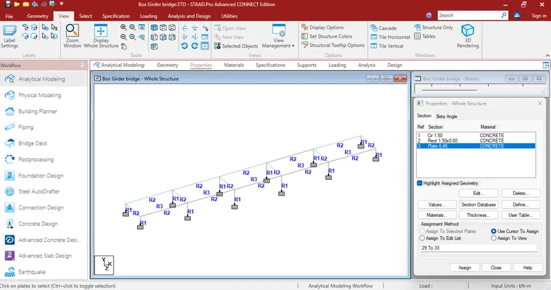
Given dimensions:
- Span length (L): 20 m
- Width of box girder (b): 11 m
- Depth of girder (h): 2.75 m
- Thickness of bottom flange (t_bottom): 0.50 m
- Thickness of top flange (t_top): 0.25 m
- Thickness of top haunch (t_haunch): 0.45 m
- Density of concrete (ρ_concrete): 2400 kg/m³
Calculate the self-weight of the girder:
Calculate the volume of the girder:
- Volume = Length × Width × Depth
- Volume = 20 m × 11 m × 2.75 m = 605 m³
Calculate the volume of the top flange:
- Volume_top_flange = Width × Thickness_top_flange × Length
- Volume_top_flange = 11 m × 0.25 m × 20 m = 55 m³
Calculate the volume of the bottom flange:
- Volume_bottom_flange = Width × Thickness_bottom_flange × Length
- Volume_bottom_flange = 11 m × 0.50 m × 20 m = 110 m³
Calculate the volume of the haunch:
- Volume_haunch = (Width × Thickness_haunch × Length) / 2
- Volume_haunch = (11 m × 0.45 m × 20 m) / 2 = 49.5 m³
Calculate the total volume of concrete:
- Total_volume = Volume + Volume_top_flange + Volume_bottom_flange + Volume_haunch
- Total_volume = 605 m³ + 55 m³ + 110 m³ + 49.5 m³ = 819.5 m³
Calculate the self-weight of the girder:
- Self_weight = Total_volume × Density_concrete
- Self_weight = 819.5 m³ × 2400 kg/m³ = 1,967,200 kg
Example Calculation: Bending Moment
Assuming a uniform load of 20 kN/m (dead load) and a span length of 20 m:
Calculate the total load on the girder:
- Total_load = Uniform_load × Span_length
- Total_load = 20 kN/m × 20 m = 400 kN
Calculate the maximum bending moment (uniformly loaded simple span beam):
- Maximum_moment = (Total_load × Span_length) / 8
- Maximum_moment = (400 kN × 20 m) / 8 = 1000 kNm
Assumptions:
- Dead Load = 10 kN/m
- Live Load = 20 kN/m
- Wind Load = 5 kN/m
Given Data:
- Span length (L) = 20 m
- Width of girder (b) = 11 m
- Depth of girder (h) = 2.75 m
Load Combinations:
-
1.4 * Dead Load + 1.7 * Live Load: Load Combination = 1.4 * 10 kN/m + 1.7 * 20 kN/m = 14 kN/m + 34 kN/m = 48 kN/m
-
1.2 * Dead Load + 1.5 * Live Load + 1.2 * Wind Load: Load Combination = 1.2 * 10 kN/m + 1.5 * 20 kN/m + 1.2 * 5 kN/m = 12 kN/m + 30 kN/m + 6 kN/m = 48 kN/m
-
1.2 * Dead Load - 1.2 * Wind Load: Load Combination = 1.2 * 10 kN/m - 1.2 * 5 kN/m = 12 kN/m - 6 kN/m = 6 kN/m
-
1.2 * Dead Load + 1.2 * Wind Load: Load Combination = 1.2 * 10 kN/m + 1.2 * 5 kN/m = 12 kN/m + 6 kN/m = 18 kN/m
-
Dead Load + Live Load: Load Combination = 10 kN/m + 20 kN/m = 30 kN/m
-
Dead Load + Wind Load: Load Combination = 10 kN/m + 5 kN/m = 15 kN/m
Interpretation of Load Combination Results:
-
1.4 * Dead Load + 1.7 * Live Load: This combination represents a scenario where the structure experiences higher live loads, which are dynamic loads caused by vehicles and pedestrians. The structure should be designed to safely support these combined loads without excessive deflections or stresses.
-
1.2 * Dead Load + 1.5 * Live Load + 1.2 * Wind Load: This combination accounts for both live loads and wind loads, considering their simultaneous effects. Wind loads can induce lateral forces on the structure, requiring adequate resistance against lateral movement and torsion.
-
1.2 * Dead Load - 1.2 * Wind Load: This combination represents a scenario where wind acts against the dead load. A negative wind load indicates that the wind is exerting a force opposite to the structure's dead load. The structure should be stable under this combination.
-
1.2 * Dead Load + 1.2 * Wind Load: This combination considers a moderate wind load along with the dead load. It's important to ensure that the structure can handle both vertical and lateral loads effectively.
-
Dead Load + Live Load: This combination represents the combined effect of static dead loads and dynamic live loads. The structure must withstand the maximum loads imposed by vehicles, pedestrians, and other live load sources.
-
Dead Load + Wind Load: This combination accounts for the static dead load and the lateral wind load. The structure must be designed to resist wind-induced forces while maintaining stability.
Overall Analysis: Analyzing the results of these load combinations is crucial to ensure that the structure meets safety and performance requirements. The structure's performance is assessed by checking factors such as bending moments, shear forces, deflections, and stability against different limit states.
Design a fixed rectangular column:
Assumptions:
- Dead Load: 200 kN
- Live Load: 300 kN
- Dimensions of the column base: 2.5 m x 2.5 m
- Concrete Strength: f'c = 25 MPa
- Allowable Bending Stress: 0.45 * f'c
Design Steps:
1. Calculate Axial Load (P): P = Dead Load + Live Load P = 200 kN + 300 kN = 500 kN
2. Determine Moments (Mx and My): Assuming a symmetrical loading, the moments are equal in both directions. Mx = My = P * (L/2) = 500 kN * (2.5 m / 2) = 625 kNm
3. Calculate Bending Stress (σ): σ = M / (b * h^2 / 6) Assume column width (b) = 2.5 m, and depth (h) = 2.5 m.
σ = 625 * 10^6 / (2.5 * (2.5^2) / 6) σ ≈ 100 MPa
4. Check Bending Stress against Allowable Stress: Allowable Bending Stress = 0.45 * f'c = 0.45 * 25 MPa = 11.25 MPa
Since 100 MPa > 11.25 MPa, the column's bending stress exceeds the allowable limit. This indicates that the selected column dimensions are inadequate to resist the bending moment. we would need to increase the dimensions or reinforce the column with additional materials (e.g., steel reinforcement).
5. Modify Column Dimensions: Increase the width and depth of the column to ensure that the calculated bending stress falls within the allowable limit.
Calculation for the design of a fixed reinforced concrete (RC) pier:
Given Data:
- Dead Load (DL): 200 kN
- Live Load (LL): 300 kN
- Concrete Strength (f'c): 25 MPa
- Steel Strength (fy): 415 MPa
- Seismic Zone: Zone II
Design Steps:
1. Calculate Axial Load and Moments: Axial Load (P) = Dead Load + Live Load P = 200 kN + 300 kN = 500 kN
2. Select Column Dimensions: Assume the initial column dimensions:
- Width (b) = 400 mm
- Depth (d) = 600 mm
3. Calculate Bending Moment: Assuming moments are equal in both directions: Moment (Mx) = Moment (My) = P * (L/2) = 500 kN * (2.5 m / 2) = 625 kNm
4. Calculate Bending Stress: Bending stress (σ) = Mx / (b * d^2 / 6) σ = 625 * 10^6 / (400 mm * (600 mm)^2 / 6) σ ≈ 58.59 MPa
5. Check Bending Stress against Allowable Stress: Assuming allowable bending stress for concrete is 0.45 * f'c = 0.45 * 25 MPa = 11.25 MPa Assuming allowable bending stress for steel is fy = 415 MPa
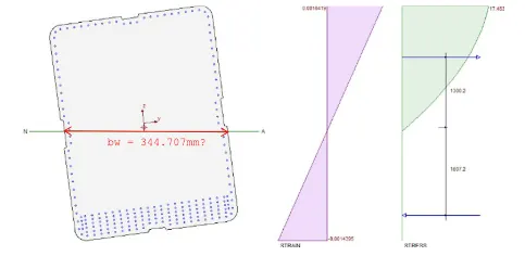
Hence, 58.59 MPa > 11.25 MPa for concrete and steel, the column dimensions are inadequate to resist the bending moment.
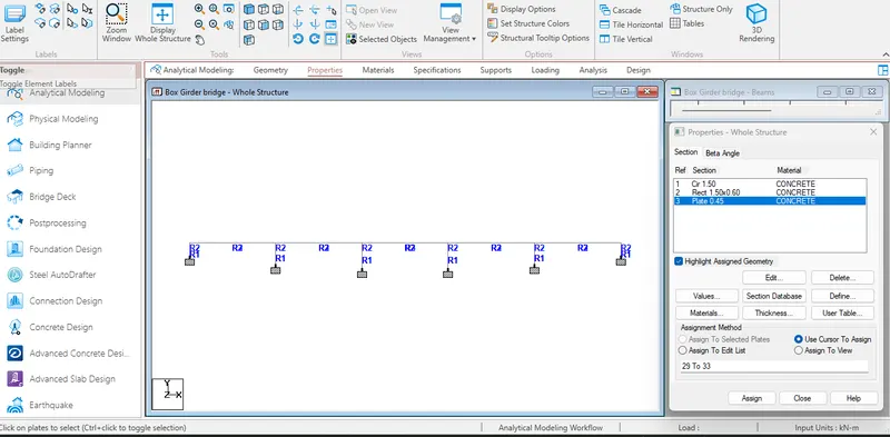
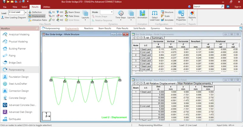
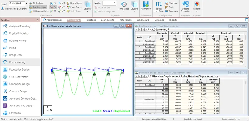
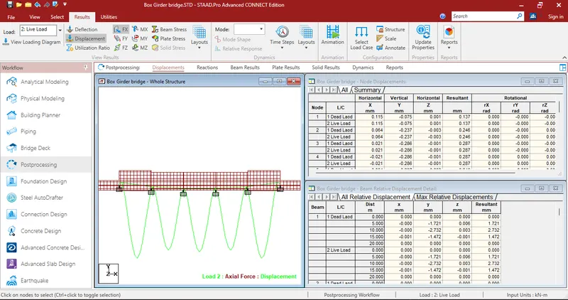
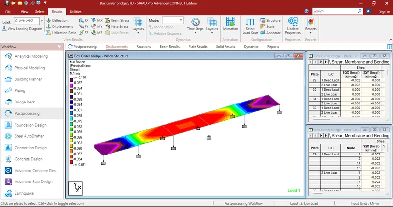
Detailing Fixed Pier: