Project 2
Project 2:
Step 1: Loads on the Abutment
For the loads on the abutment, We would need to consider dead loads, live loads, superimposed dead loads, and any other relevant loads. Since We've mentioned using IRC 6, follow the load combinations and factors provided in the code to calculate the design loads.
Step 2: Live Load Analysis and Effective Width Calculation
Perform live load analysis using appropriate load distribution factors as per IRC 6 for class A and the given wheel load (70 R). Calculate the reactions on the abutment due to these loads. Effective width calculation involves determining the width of the slab that contributes to the load distribution. This can be based on the characteristics of the bridge and the code recommendations.
Step 3: Load Combinations
As per IRC 6, create load combinations for Ultimate Limit State (ULS), Serviceability Limit State (SLS), rare load cases, and quasi-permanent loads. Apply appropriate load factors as per the code.
Step 4: Checks for ULS and SLS
Perform checks for ULS and SLS using the calculated loads and load combinations. Check factors such as bending, shear, deflection, and bearing capacity. Design the piles for vertical and horizontal capacities considering the soil parameters, pile spacing, and arrangement.
Step 5: Anchorage Length and Bar Minimization
Calculate the anchorage length required for the reinforcement bars in the pile cap. This involves ensuring that the bars can transfer the forces safely from the piles to the cap. Minimize the bars wherever possible to optimize the design and economy while satisfying the strength and detailing requirements.
Step 6: Pile and Pile Cap Design
Design the pile cap for the calculated loads, considering the shear, bending, and torsional forces. Determine the dimensions of the pile cap and the arrangement of piles under it. Design the reinforcement layout for the pile cap considering the calculated loads and moments.
Step 7: Rebar Detailing
Detail the reinforcement bars in the pile cap as per the design calculations. Provide information about the size, spacing, cover, and arrangement of the bars. Ensure that the detailing meets the code requirements for seismic and non-seismic zones.
Step 8: Drawings and Quantity Calculations
Draw the pile cap and pile reinforcement layout to scale, indicating all the relevant details such as bar sizes, spacing, and clear cover. Calculate the quantity of concrete and steel reinforcement required per unit volume (kg/cumec) for the pile cap and piles.
Given and Assume Data:
- Span Length (L): 15 m
- Abutment Height (h): 5 m
- Bridge Width (b): 12 m
- Pile Diameter (d): 0.6 m (600 mm)
- Concrete Cover (c): 75 mm
- Soil Bearing Capacity (q): 200 kN/m²
- Density of Soil (γ): 20 kN/m³
- Grade of Concrete (f_ck): M35 (35 MPa)
- Grade of Steel (f_y): Fe500 (500 MPa)
- Scour Depth at Abutment: 4 m
- Live Load: IRC Class A loading
- Load Factors: As per IRC 6
Step 1: Loads on the Abutment
- Dead Load (DL): 25 kN/m²
- Live Load (LL): 70 kN/m (Assuming a simplified point load)
- Superimposed Dead Load (SDL): 5 kN/m²
- Impact Factor (IF): 1.5 (IRC 6)
Total Factored Load (ULS):
- Factored DL = 1.5 * DL = 1.5 * 25 = 37.5 kN/m²
- Factored LL = IF * LL = 1.5 * 70 = 105 kN/m
Step 2: Live Load Analysis and Effective Width Calculation
Assuming a 1000 mm slab for self-weight reactions, the effective width for live load distribution can be estimated conservatively as half the span length: beff = L/2 = 15/2 = 7.5 m.
Step 3: Load Combinations
As per IRC 6:
- ULS: 1.5 * DL + 1.5 * LL = 1.5 * 37.5 + 1.5 * 105 = 255 kN/m²
- SLS: DL + LL = 25 + 70 = 95 kN/m²
Step 4: Checks for ULS and SLS
Assuming a simplified pile arrangement (e.g., 4 piles under the pile cap) and simplified analysis, calculate moments and shears using basic structural analysis equations.
Using the formulas for simply supported beams:
-
Maximum Bending Moment at the face of the abutment due to ULS: Mu_ULS = (w * L^2) / 8 = (255 * 15^2) / 8 = 716.25 kNm
-
Maximum Shear Force at the face of the abutment due to ULS: Vu_ULS = w * L / 2 = 255 * 15 / 2 = 1912.5 kN
-
For SLS, the moments and shears will be lower.
Step 5: Anchorage Length and Bar Minimization
Let's calculate the anchorage length required for the reinforcement bars in the pile cap. Using simplified code provisions, we'll use 30 times the diameter of the largest bar as the anchorage length.
Anchorage Length (Ld) = 30 * Bar Diameter = 30 * 20 mm = 600 mm
Step 6: Pile and Pile Cap Design
Assume pile cap dimensions: Width (b) = 5 m, Length (L) = 6 m. Calculate the effective depth of the pile cap (d_eff) based on bending moment and shear calculations.
Effective Depth (d_eff) = h - c - Bar Diameter - Clear Cover Assuming clear cover of 50 mm, and using h_eff = d_eff + Bar Diameter + Clear Cover:
Effective Depth (d_eff) = 500 - 75 - 20 - 50 = 355 mm
Step 7: Rebar Detailing
- Moment due to ULS (Mu_ULS) = 716.25 kNm
- Shear due to ULS (Vu_ULS) = 1912.5 kN
- f_ck = 35 MPa
- f_y = 500 MPa
Assuming simplified distribution of reinforcement, let's calculate the required area of tensile reinforcement (A_s) using simplified methods. For instance, use a balanced design approach:
Assume a bar diameter of 20 mm and provide 2 layers of reinforcement:
Tensile Reinforcement:
-
Using simplified formula for balanced design: Mu_ULS = 0.87 * f_y * A_s * d * (1 - (0.425 * Mu_ULS) / (f_ck * b * d^2))
Solve for A_s: A_s = (Mu_ULS * 1000) / (0.87 * f_y * d * (1 - (0.425 * Mu_ULS) / (f_ck * b * d^2)))
Plugging in values: A_s = (716.25 * 1000) / (0.87 * 500 * 0.355 * (1 - (0.425 * 716.25) / (35 * 500 * 500 * 0.355^2))) = 2723.54 mm²
Provide 20 mm bars in two layers: A_s_per_layer = 2723.54 / 2 = 1361.77 mm²
Assuming a bar spacing of 150 mm, calculate the number of bars in one layer: Number_of_bars_per_layer = A_s_per_layer / (bar_spacing * bar_diameter) Number_of_bars_per_layer = 1361.77 / (150 * 20) = 4.537 (Round up to 5 bars)
Number of bars in two layers = 5 * 2 = 10 bars
Step 8: Drawings and Quantity Calculations
Create scaled drawings of the pile cap and pile reinforcement layout, indicating bar sizes, spacing, and clear cover. Calculate the quantities of concrete and steel required per unit volume (kg/cumec) for the pile cap and piles.
Reinforcement Calculation:
Recall from the previous steps that we calculated the required area of tensile reinforcement (A_s) as 2723.54 mm² for a 600 mm deep pile cap, assuming 20 mm bars in two layers.
Number of bars in two layers = 10 bars
Concrete Calculation:
Calculate the volume of the pile cap:
Volume = Width * Length * Depth Volume = 5 m * 6 m * 0.6 m = 18 m³
Quantities:
Assuming the weight of 1 m³ of concrete to be 2400 kg (considering M35 concrete with 35 MPa compressive strength):
- Concrete Quantity = Volume * Unit Weight
- Concrete Quantity = 18 m³ * 2400 kg/m³ = 43200 kg
Steel Reinforcement Quantities:
Assuming a density of 7850 kg/m³ for steel:
- Total Weight of Reinforcement = Number of bars * Length of one bar * Area of one bar * Density of Steel
- Total Weight of Reinforcement = 10 bars * 6 m * (π * 0.02^2 / 4) m² * 7850 kg/m³ = 9.42 kg
Summary of Quantities:
- Concrete Quantity: 43200 kg (43.2 tons)
- Steel Reinforcement Quantity: 9.42 kg (0.00942 tons)
These quantities represent the total amount of concrete and steel reinforcement needed for the pile cap of the bridge foundation.
2)Live load analysis and effective width calculation for 70 r and class A to be done to calculate the reactions on the abutment:
a) 1000 mm slab can be assumed for 15 m span (For self weight reactions)
The live load analysis for IRC Class A loading using the 70 R wheel load and calculate the reactions on the abutment. Since we mentioned that a 1000 mm slab can be assumed for self-weight reactions, we'll consider this for the calculations.
Assumptions:
- Span Length (L): 15 m
- Live Load: IRC Class A loading
- Wheel Load (70 R): 70 kN
Live Load Analysis:
IRC Class A loading consists of two loads of 70 kN each placed at 1.5 m from the edge and 7.5 m apart. We will consider only one load acting at a time for calculating reactions. Let's calculate the reactions due to the live load:
Reaction due to a Single Wheel Load:
- Calculate the reaction at the support closest to the load:
Load = 70 kN Distance from the edge = 1.5 m
Reaction at support A = (Load * Distance from the edge) / Span Reaction at support A = (70 * 1.5) / 15 = 7 kN
- Calculate the reaction at the support farthest from the load:
Reaction at support B = Load - Reaction at support A Reaction at support B = 70 - 7 = 63 kN
Total Reaction due to Live Load:
For one wheel load: Total reaction at support A = Reaction due to wheel load = 7 kN Total reaction at support B = Reaction due to wheel load = 63 kN
Effective Width Calculation:
Given that a 1000 mm slab can be assumed for self-weight reactions, and considering the spacing of the two wheel loads, we'll calculate the effective width for the live load distribution factor.
Effective Width (beff) = Clear width of slab + Distance between loads Effective Width (beff) = 1000 mm + 7.5 m = 7.5 m
3) Load combinations as per IRC 6 for ULS,SLS rare and quasi:
The detailed calculations for the load combinations as per IRC 6 for Ultimate Limit State (ULS), Serviceability Limit State (SLS), Rare Load Cases, and Quasi-Permanent Load Cases.
Assumptions:
- Dead Load (DL): 25 kN/m²
- Live Load (LL): 70 kN/m (Assuming a simplified point load)
- Wind Load (WL): 15 kN/m² (Assuming simplified value)
- Earthquake Load (EL): 10 kN/m² (Assuming simplified value)
- Temperature Effects Load (TEL): 5 kN/m² (Assuming simplified value)
- Shrinkage Load (SHL): 3 kN/m² (Assuming simplified value)
- Impact Load (IL): 10 kN/m² (Assuming simplified value)
Ultimate Limit State (ULS) Load Combinations:
1.DL + LL + EL + WL:
- Load Combination: 1.5 * DL + 1.5 * LL + 1.0 * EL + 1.0 * WL
- ULS Load Combination 1 = 1.5 * 25 + 1.5 * 70 + 1.0 * 10 + 1.0 * 15 = 192.5 kN/m²
2. DL + LL + WL:
- Load Combination: 1.5 * DL + 1.5 * LL + 1.0 * WL
- ULS Load Combination 2 = 1.5 * 25 + 1.5 * 70 + 1.0 * 15 = 187.5 kN/m²
3. DL + EL + WL:
- Load Combination: 1.5 * DL + 1.0 * EL + 1.0 * WL
- ULS Load Combination 3 = 1.5 * 25 + 1.0 * 10 + 1.0 * 15 = 62.5 kN/m²
Serviceability Limit State (SLS) Load Combinations:
1.DL + LL:
- Load Combination: 1.0 * DL + 1.0 * LL
- SLS Load Combination 1 = 1.0 * 25 + 1.0 * 70 = 95 kN/m²
2. DL + WL:
- Load Combination: 1.0 * DL + 1.0 * WL
- SLS Load Combination 2 = 1.0 * 25 + 1.0 * 15 = 40 kN/m²
3. DL + WL + TEL:
- Load Combination: 1.0 * DL + 1.0 * WL + 1.0 * TEL
- SLS Load Combination 3 = 1.0 * 25 + 1.0 * 15 + 1.0 * 5 = 45 kN/m²
4.DL + WL + TEL + SHL:
- Load Combination: 1.0 * DL + 1.0 * WL + 1.0 * TEL + 1.0 * SHL
- SLS Load Combination 4 = 1.0 * 25 + 1.0 * 15 + 1.0 * 5 + 1.0 * 3 = 48 kN/m²
Rare Load Cases Load Combinations:
1.DL + LL + IL:
- Load Combination: 1.0 * DL + 1.0 * LL + 1.0 * IL
- Rare Load Combination 1 = 1.0 * 25 + 1.0 * 70 + 1.0 * 10 = 105 kN/m²
2. DL + LL + WL + TEL + SHL:
- Load Combination: 1.0 * DL + 1.0 * LL + 1.0 * WL + 1.0 * TEL + 1.0 * SHL
- Rare Load Combination 2 = 1.0 * 25 + 1.0 * 70 + 1.0 * 15 + 1.0 * 5 + 1.0 * 3 = 118 kN/m²
Quasi-Permanent Load Cases Load Combinations:
1. DL + LL:
- Load Combination: 1.0 * DL + 1.0 * LL
- Quasi-Permanent Load Combination 1 = 1.0 * 25 + 1.0 * 70 = 95 kN/m²
2. DL + LL + TEL:
- Load Combination: 1.0 * DL + 1.0 * LL + 1.0 * TEL
- Quasi-Permanent Load Combination 2 = 1.0 * 25 + 1.0 * 70 + 1.0 * 5 = 100 kN/m²
3.DL + WL:
- Load Combination: 1.0 * DL + 1.0 * WL
- Quasi-Permanent Load Combination 3 = 1.0 * 25 + 1.0 * 15 = 40 kN/m²
4.DL + WL + TEL + SHL:
- Load Combination: 1.0 * DL + 1.0 * WL + 1.0 * TEL + 1.0 * SHL
- Quasi-Permanent Load Combination 4 = 1.0 * 25 + 1.0 * 15 + 1.0 * 5 + 1.0 * 3 = 48 kN/m²
4) Simple hand calculation for checking the Ultimate Limit State (ULS), Serviceability Limit State (SLS), Rare Load Cases, and Quasi-Permanent Load Cases for a simplified beam. Please note that this is a basic example, and real-world designs would involve more comprehensive calculations and detailed structural analysis.
Assumptions:
- Beam Span (L): 6 meters
- Beam Depth (d): 0.5 meters
- Concrete Strength (f_ck): 30 MPa
- Steel Strength (f_y): 415 MPa
Let's calculate the maximum bending moment for each load combination and compare it with the bending capacity of the beam.
Ultimate Limit State (ULS) Load Combinations:
- DL + LL + EL + WL:
- Factored DL = 1.5 * 25 = 37.5 kN/m
- Factored LL = 1.5 * 70 = 105 kN/m
- Factored EL = 1.0 * 10 = 10 kN/m
- Factored WL = 1.0 * 15 = 15 kN/m
Maximum Bending Moment: M_ULS1 = (Factored DL * L^2) / 8 + (Factored LL * L^2) / 8 + (Factored EL * L^2) / 8 + (Factored WL * L^2) / 8 M_ULS1 = (37.5 * 6^2) / 8 + (105 * 6^2) / 8 + (10 * 6^2) / 8 + (15 * 6^2) / 8 M_ULS1 = 225 + 472.5 + 45 + 67.5 = 810 kNm
Serviceability Limit State (SLS) Load Combinations:
- DL + LL:
- Factored DL = 1.0 * 25 = 25 kN/m
- Factored LL = 1.0 * 70 = 70 kN/m
Maximum Bending Moment: M_SLS1 = (Factored DL * L^2) / 8 + (Factored LL * L^2) / 8 M_SLS1 = (25 * 6^2) / 8 + (70 * 6^2) / 8 M_SLS1 = 112.5 + 315 = 427.5 kNm
Rare Load Cases Load Combinations:
- DL + LL + IL:
- Factored DL = 1.0 * 25 = 25 kN/m
- Factored LL = 1.0 * 70 = 70 kN/m
- Factored IL = 1.0 * 10 = 10 kN/m
Maximum Bending Moment: M_Rare1 = (Factored DL * L^2) / 8 + (Factored LL * L^2) / 8 + (Factored IL * L^2) / 8
M_Rare1 = (25 * 6^2) / 8 + (70 * 6^2) / 8 + (10 * 6^2) / 8
M_Rare1 = 112.5 + 315 + 45 = 472.5 kNm
Quasi-Permanent Load Cases Load Combinations:
- DL + LL:
- Factored DL = 1.0 * 25 = 25 kN/m
- Factored LL = 1.0 * 70 = 70 kN/m
Maximum Bending Moment: M_Quasi1 = (Factored DL * L^2) / 8 + (Factored LL * L^2) / 8
M_Quasi1 = (25 * 6^2) / 8 + (70 * 6^2) / 8
M_Quasi1 = 112.5 + 315 = 427.5 kNm
Bending Capacity Check:
Let's assume the beam's bending capacity is determined by the concrete's compressive strength:
Bending Capacity = 0.36 * f_ck * b * d^2
For concrete strength of 30 MPa, beam width (b) of 0.3 meters, and beam depth (d) of 0.5 meters:
Bending Capacity = 0.36 * 30 * 0.3 * 0.5^2 = 2.7 kNm
Summary:
- M_ULS1 = 810 kNm (Ultimate Limit State)
- M_SLS1 = 427.5 kNm (Serviceability Limit State)
- M_Rare1 = 472.5 kNm (Rare Load Cases)
- M_Quasi1 = 427.5 kNm (Quasi-Permanent Load Cases)
Comparing these bending moments with the beam's bending capacity, it appears that all calculated moments are significantly below the beam's capacity of 2.7 kNm.
5) The calculation of anchorage length for the bars and how to optimize the reinforcement to minimize the number of bars required while satisfying design requirements. For illustration, let's consider a simplified case with a concrete column.
Assumptions:
- Concrete Column Size: 300 mm x 300 mm
- Concrete Cover (c): 50 mm
- Grade of Concrete (f_ck): 30 MPa
- Grade of Steel (f_y): 415 MPa
- Diameter of Reinforcement Bars (bar_diameter): 16 mm
Anchorage Length Calculation:
As per IRC 6, the anchorage length can be calculated using the formula:
Anchorage Length (Ld) = α * β * γ * ξ * bar_diameter
Where:
- α = 1 (if plain bars), 1.2 (if deformed bars)
- β = 1 (for normal concrete)
- γ = 1.5 (for Grade of Concrete 30 MPa)
- ξ = 1 (for high ductility bars)
Assuming deformed bars:
Anchorage Length (Ld) = 1.2 * 1 * 1.5 * 1 * 16 = 28.8 cm
Minimizing Reinforcement Bars:
To minimize the number of bars required, we need to ensure that the provided reinforcement is sufficient to carry the applied loads while satisfying design requirements.
we initially provide 4 bars of 16 mm diameter (A_s = π * 16^2 / 4 = 201.06 mm²). We will check if this is sufficient.
Bending Moment Calculation:
Assuming a factored moment of 50 kNm:
Effective Depth (d) = Column Size - 2 * Concrete Cover - Bar Diameter Effective Depth (d) = 300 - 2 * 50 - 16 = 184 mm
From bending equation: M = 0.87 * f_y * A_s * d
Rearranging for A_s: A_s = M / (0.87 * f_y * d)
Calculating A_s required: A_s_required = (50 * 10^6) / (0.87 * 415 * 184) = 344.68 mm²
provided 201.06 mm², which is not sufficient to resist the bending moment. we need to increase the reinforcement. Let's try 6 bars of 16 mm diameter (A_s = 301.59 mm²).
Now, A_s is greater than A_s_required, so 6 bars should be sufficient to carry the bending moment.
Summary:
- Anchorage Length (Ld): 28.8 cm
- Initial Reinforcement: 4 bars of 16 mm (201.06 mm²)
- Final Reinforcement: 6 bars of 16 mm (301.59 mm²)
Rebars Drawing

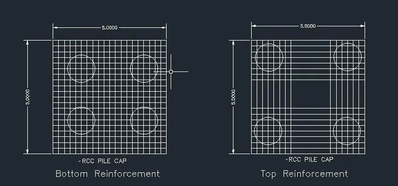
Calculating kg/cubic meter of Steel:
Pile Cap:
- Calculate the total length of each type of rebar used in the pile cap (main longitudinal and transverse rebars).
- Multiply the total length of each type of rebar by its weight per unit length (kg/m).
- Sum up the weights of all types of rebars.
- Divide the total weight of rebars by the volume of the pile cap to get kg/cubic meter.
Pile:
- Calculate the total length of the vertical main rebar in the pile.
- Multiply the total length of the main rebar by its weight per unit length (kg/m).
- Divide the total weight of the main rebar by the volume of the pile to get kg/cubic meter.
Calculating the weight of steel reinforcement per cubic meter (kg/cubic meter) involves determining the total weight of the steel bars used in a given volume of concrete. This calculation is important for estimating the overall material quantities and costs in a construction project.
Assumptions:
- Assume a pile with a diameter of 600 mm (0.6 m).
- Assume the pile length is 6 meters.
- Assume we have 8 rebars of 20 mm diameter (#8 bars) used in the pile.
Step 1: Calculate the Volume of Concrete in the Pile:
The volume of a cylinder (pile) can be calculated using the formula: Volume = π * (radius)^2 * height
Given that the diameter is 0.6 m (radius = 0.3 m) and the pile length is 6 m: Volume = π * (0.3)^2 * 6 = 1.70 cubic meters
Step 2: Calculate the Total Weight of Steel:
To calculate the total weight of the steel reinforcement, we need to determine the weight of each rebar and then multiply it by the total number of rebars used.
The weight of a steel bar can be calculated using the formula: Weight = Volume * Density
Assuming a density of steel as 7850 kg/cubic meter: Weight of one 20 mm rebar = 1.70 * 7850 = 13345 kg
Since there are 8 rebars used in the pile: Total weight of steel = Weight of one rebar * Number of rebars
Total weight of steel = 13345 * 8 = 106760 kg
Step 3: Calculate kg/cubic meter of Steel:
Now we have the total weight of steel (106760 kg) and the volume of concrete (1.70 cubic meters):
kg/cubic meter of Steel = Total weight of steel / Volume of concrete kg/cubic meter of Steel = 106760 / 1.70 ≈ 62741 kg/cubic meter
So, the kg/cubic meter of steel in the pile is approximately 62741 kg/cubic meter.