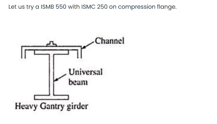
Project 2
1)ANS:
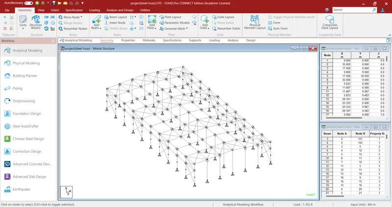
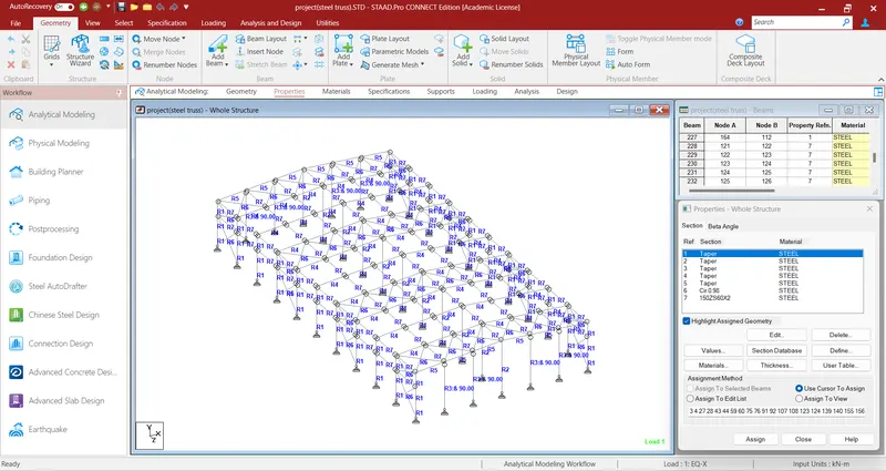
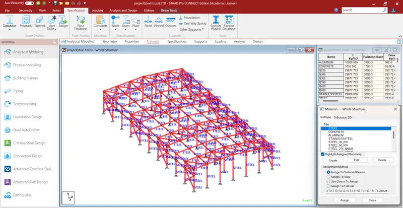
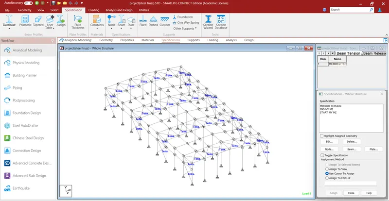
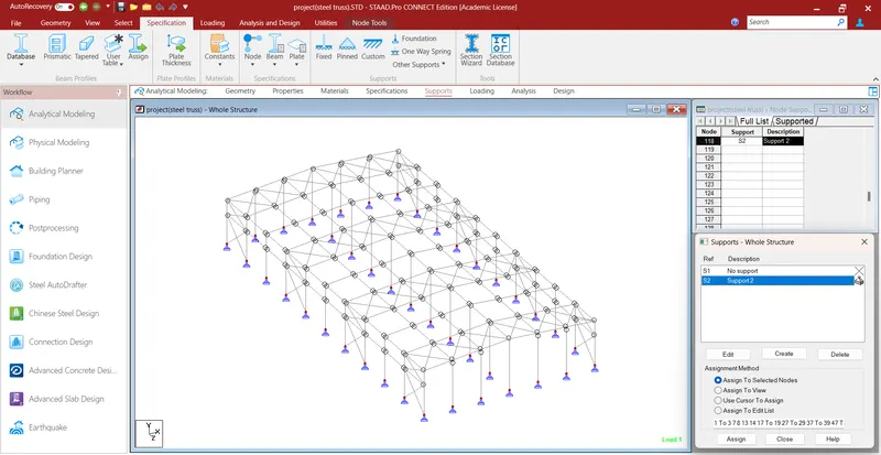
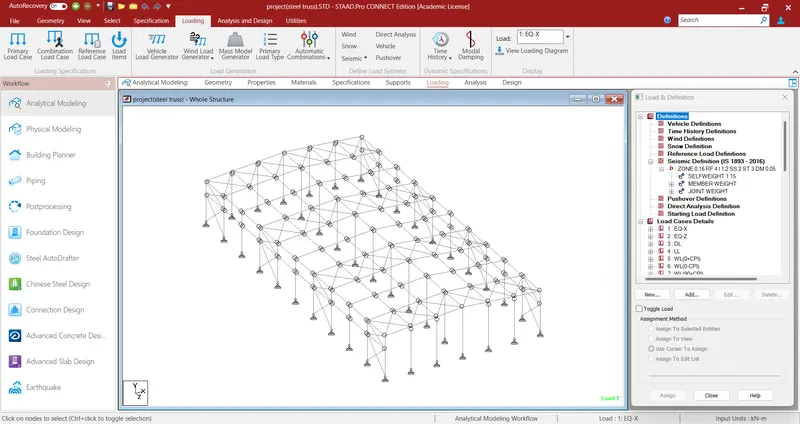
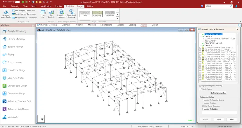
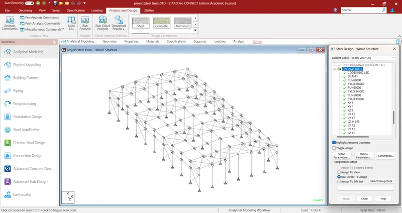
1. EQ+X
- IS 1893 Load-X 1
2. EQ+Z
- IS 1893 Load-Z 1
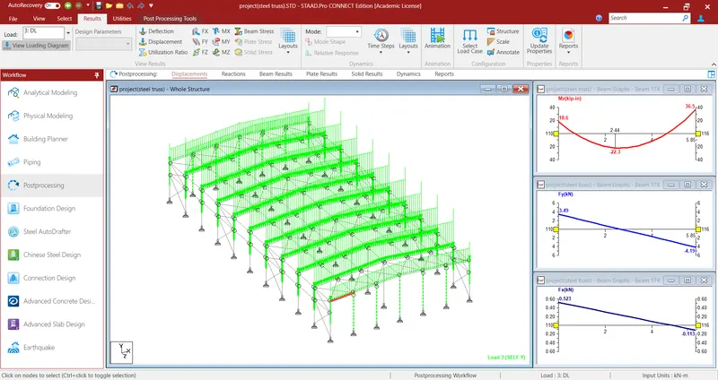
3. DEAD LOAD
- Self weight Y -1.15
- Main frame rafter GY -1.55 KN/m
- Gable frame rafter GY -0.775 KN/m
- Main frame column GY -1.2 KN/m
- Gable frame column GY - 0.6 KN/m
- Gable / wind column GY -1.04 KN/m
- Wind frame point load FY - 1.14 KN/m
- Gable frame point load FY -0.57 KN/m
4. LIVE LOAD
- Main frame rafter GY -4.85 KN/m
- Gable frame rafter GY - 2.425 KN/m
- Wind frame point load FY - 4.15 KN/m
- Gable frame point load FY - 2.06 KN/m
5. WIND LOAD
- WL(0+Cpi)
- WL(0-Cpi)
- WL(90+Cpi)
- WL(90-Cpi)
DESIGN OF STEEL COLUMN:
Solution:
Flange thickness = T = 12.7 mm.
Overall height of Column ISMB400 = h = 400 mm.
Clear depth between flanges = d = 400 – (12.7 x 2)
= 374.6 mm.
Thickness of web = t = 10.6mm.
Flange width = 2b = bf = 250 mm.
Hence, half Flange Width = b = 125 mm.
Self –weight = w = 0.822 kN/m.
Area of cross-section = A = 10466 mm2.
Radius of gyration about x = rx = 166.1 mm.
Radius of gyration about y = ry = 51.6 mm.
Type of section:
b/T = 125/12.7= 9.8 < 10.5
d/t =374.6/10.6 =35.3 < 42
(Table 3.1 of IS: 800)
Hence, cross-section can be classified as “COMPACT”.
Effective Sectional Area, Ae = 10,466 mm2
(Since there is no hole, (Clause 7.3.2 of IS: 800)
no reduction has been considered)
Effective Length:
As, both ends are pin-jointed effective length, KLx = KLy = 3m
Slenderness ratios:
KLx/rx = 9000/166.1 =54.1
KLy/ry = 9000/51.6 =174.41
Non-dimensional Effective Slenderness ratio, λ">λ3.3X7^2/8:
λ">λ
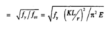
=
Value of ϕ">ϕ from equation:

Hence, α">αα = 0.34 for buckling class ‘b’ will be considered.
Hence, ϕ">ϕϕ = 0.5 x [1+0.34 x (0.654-0.2)+0.6542] = 0.791
Calculation of x from equation x:
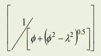 = 0.809
Calculation of fcd from the following equation:
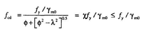
= 0.809 x 250/1.1 = 183.86 N/mm2
Factored axial load in kN.
pd = Ag fcd
= 10466 x 183.86/1000 = 1924.28 kN.
DESIGN OF RAFTER:
Solution:
Span of Rafter = 6 m
Dead load = 18KN/m
Imposed load = 40KN/m
support bearing = 100mm
yield strength = 250N/mm2
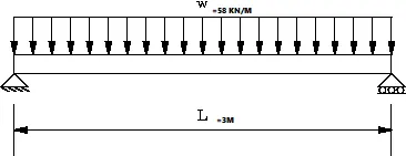
Design load calculation:
Factores load 1.5(DL+LL) =87 KN/m
Factores Bending moment = Wl^2/8">10^6WL
Section modulus Required:
Z reqd = (65.25 x x1.1) /250 =287100 mm3 = 287.1 cm3
Section classification:
ISMB-200
A = 323.3 mm2
D = 200mm
B = 100mm
t = 5.7 mm
T = 10.8 mm
Ixx = 2235.4 cm4
Iyy = 150 cm4
Zp = 375.35 cm3
Moment of resistence of the cross-section:
Md =
= (1 x 375.35 x 250) / ( 1.1)
Md = 85.306 > 65.25 KN/m
DESIGN OF BASE PLATE:
Strength of concrete, Fcu = 40 N/mm2
Yield strength of steel, fy = 250 N/mm2
Material factor, γm">γmγmFA−6XMzBL2= 1.1 KN
Factoresl oad = 1500 KN
Steel column section:
Thickness of flange, T = 12.7 mm
Area required:
Bearing strength of concrete = 0.4fcu = 0.4 x 40 = 16 N/mm2
= (1500x1000) /( 16)
= 93750 mm2
Let size of plate , Bplate = 450 mm
Dplate = 300 mm
Area of plate= 135000 mm2
projection on each side = a=b =25mm
W = (1500x1000) /( 450 x 300)
= 11.11 N/mm2
Therefore, Thickness of Base Plate, clause 7.4.3.1
`t s = √ 2.5 w ( a 2 − 0.3 b 2 ) γ m 0 f y > t f`LXσ1/σ1+σ2
ts= 7.3 mm < 12.7 mm
Size of Base plate 450 x 350 x 16 mm
DESIGN OF PEDESTAL:
Grade of concrete = 40 N/mm2
Load = 200 KN
Moment = 120 KN
Horizontal shear = 20 KN
Yield strength = 250 N/mm2
Length of base plate = 450 mm
Width of base plate = 350 mm
C/C distance of bolt in group-Z = 300 mm
C/C distance of bolt in group-X = 180 mm
Bearing strength of concrete Fc = 16 N/mm2
Depth of Column = 300 mm
Width of Column = 250 mm
Anchor Bolt Details
Dia of anchor bolts =24 mm
No:of anchor bolts in each side = 4
Total no:of anchor bolts, n = 8
Gross area of the bolt ;Asb' = 452.16 mm2
Net area of bolt 'Anb' = 352 mm2
Ultimate tensile strength of bolt 'fub' = 400 N/mm2
Fyb (anchor bolts) = 240 N/mm2
Base plate Details
Ultimate tensile strength of plate 'fu' = 490 N/mm2
Thickness of plate = 16 mm
Yield stress of plate = 330 N/mm2
Anchor bolt design
Area of the plate = 157500 mm2
Stress, Maximum pressure =
= 10.6 N/mm2 < 16 Hence OK
Minimum pressure =
= -9.04 N/mm2 < 16 Hence OK
Centroid = = 242.89 mm
a =L/2-C/3 = 144.04 mm
e = (L-Ld) / 2 =75 mm
y = (L - C/3-e) = 294.04 mm
Tension in anchor bolt along the length of plate, FT = (Mz - Fa)/Y
= 364.38
Tension per bolt = 91 KN
Shear per bolt = 1.63 KN
Shear Check
Factored shear force = Vsb = 1.63 KN
Vd,sb = 81290.9 N
= 81 KN
Factored = 65.03 KN
Tensile Check
Factored tensile force in bolt, Tb = 91.1 KN
Tensile strength of bolt Ts,b = Tn,b /
Td,b = 98.65 KN
Combined Unity Check
Vsb/Vdb = 0.025
Tb/Tdb = 0.92
Unity check = 0.85 < 1, Hence OK
Anchor Bolt Length
Bond strength in tension,
Anchor length required = Tb(3.14*
= 863.44 mm
Let Anchor Bolt Length = 900 mm
DESIGN OF Z-PURLIN:
Span of the purlin = 6 m
spacing of purlin = 1.5 m
No:of sag rods = 1
slope of the roof = 4.76 = 5 degree
Dead load:
Weight of sheeting = 6kg/m2
self weight of purlin = 4.22 kg/m2
Additional load = 10% = 0.42 kg/m2
Total Dead load = 0.106 kg/m2
Live load:
Live load on roof = 75 kg/m2
Wind Load:
Basic wind speed = 50 m/s
Terrain caterogy = 2
Building class = B
K1 = 1
K2 = 1
K3 = 1
Design wind speed, Vz = 57 m/s
Design wind pressure, Pz = 1949.9 m/s = 1.94 KN
Length of building, L = 50 m
Breadth of building, W = 30 m
Height of building, H = 10.25 m
Height of eaves, = 9 m
h/w = 0.34
L/w = 1.667
External Pressure Co-eeficient
Maximum downward =Cpe = -0.4
Maximum upward =Cpe = -0.7
Internal Pressure Co-eeficient
Maximum positive =Cpi = 0.5
Maximum negative =Cpi = -0.5
For Maximum upward wind force
Max upward Cpe = - 0.7
Cpi = - 0.5
Cpe+Cpi = -1.2
Pz = 1.95
Wind Pressure for Purlin Design = - 2.339 KN/m2
For Maximum upward wind force
Max upward Cpe = - 0.4
Cpi = - 0.5
Cpe+Cpi = -0.1
Pz = 1.95
Wind Pressure for Purlin Design = 0.195 KN/m2
Design Load Calculation
spacing of purlin 1.5 m
slope of roof = 5degree
Total dead load = 0.096
DL Normal component = 0.144 KN/m
DL Tangential component = 0.013 KN/m
Total Live load = 0.75
LL Normal component = 1.121 KN/m
LL Tangential component = 0.098 KN/m
Total Wind load = -2.339
WL Normal component = - 3.496 KN/m
WL2 WL load = 0.195 KN/m
WL Normal component = 0.291 KN/m
Maximum Normal component = DL+LL = 1.265 KN/m
Purlin section
Selected section Z200 x 6 x 2.3
Area = 8.07 cm2
Weight of purlin = 6.335 kg/m
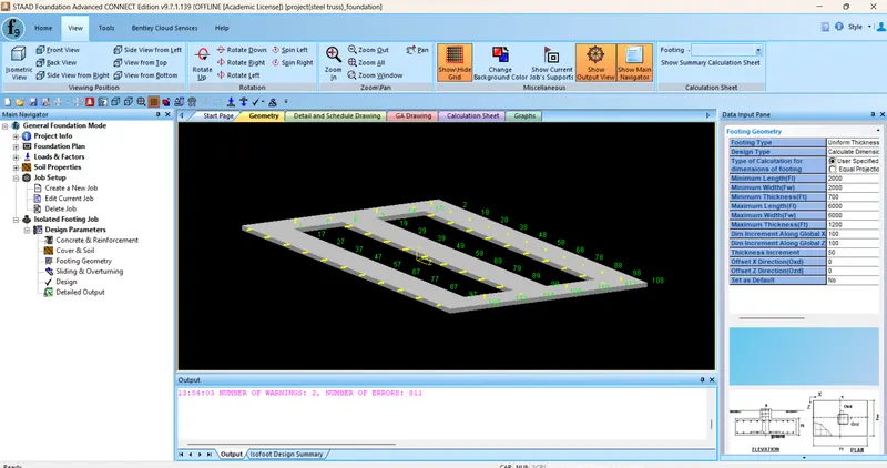
FOUNDATION DESIGN:
2)ANS: