Project 2 - Automotive Lighting
Objective
The aim of this project is to complete 3D modelling of an Rear combinational lamp and perfrom various operations in accordance the industry life cycle . The inputs given are as follow.
Lens Rib hight - MINIMUM 8-10 MM
Interferance - 1.5 MM
Thickness of Lens - 2.5 MM
Housing Thickness - 2 MM
Reflector Thickness - 2 MM
Boss - M4X10 SCREW
Procedures
Tail lamp is basically used to show any vehicle position so one should able to see from distance but as above maintained the intensity is low then it will not be clearly visible and if the intensity is too high then it will be a distraction for the back driver.
Some general material used for the lamp are listed below
|
PARTS NAMES |
MATERIAL |
|
LENS/INNER LENS |
PMMA/PC |
|
HOUSING |
PP/ABS/ASA |
|
REFLECTOR |
PC |
|
BEZEL |
PBT/PC |
|
BULB/LED |
STANDARD(P21W,P21/5W,PY21W,W5W) |
The steps performed to completed the projects are listed below.
Given surfaces
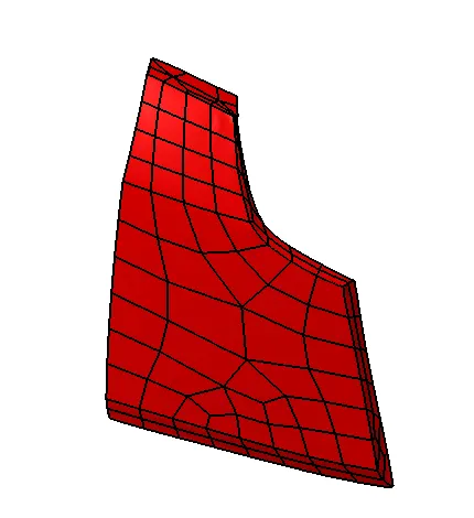
The Given surfaces were not good enough so it was rough offset and improved.
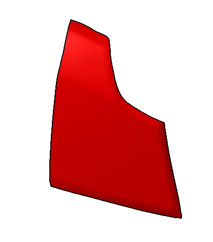
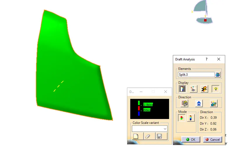
The tooling axis is created for the surface.
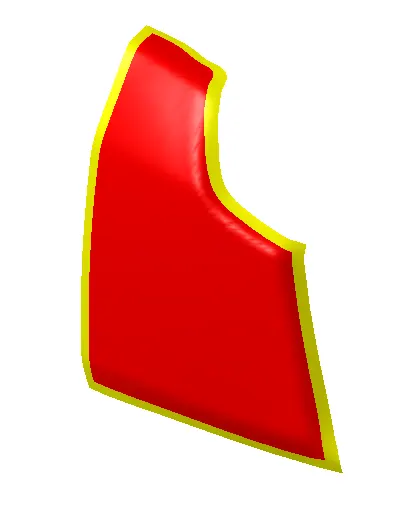
Once the tooling axis is done the seal track for the Hot plate welding is to be created. The B & C surfaces are created .
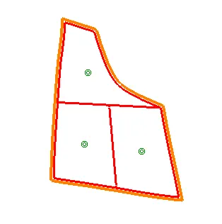
The lens seal leg is created and made as solid
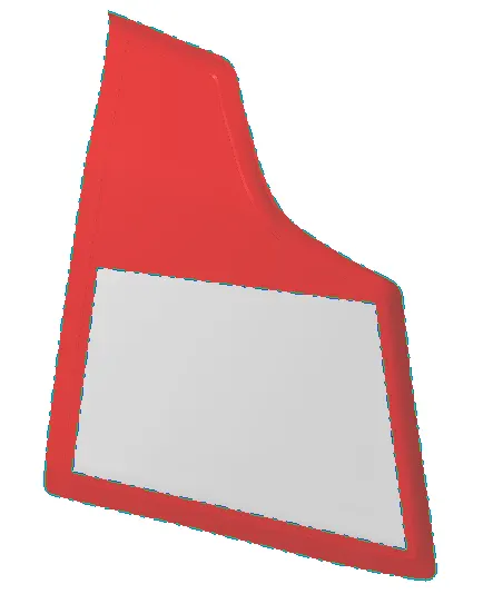
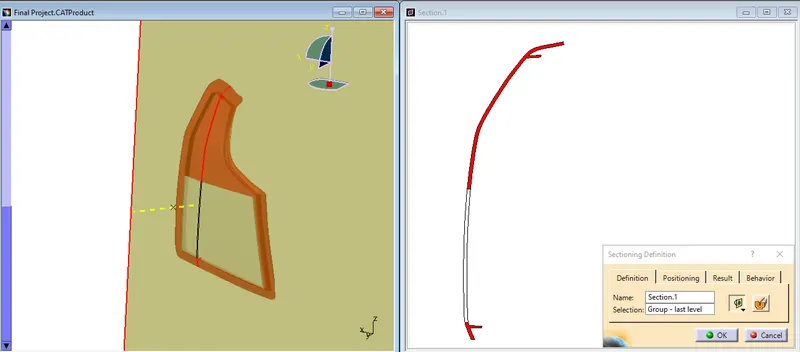
Once the lens section is done we are creating the Housing and the reflectors.
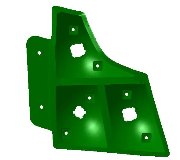
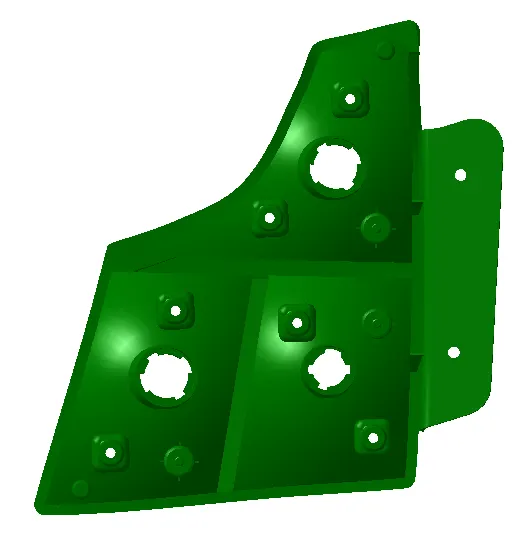
Now the reflector is to created for the Lamp.
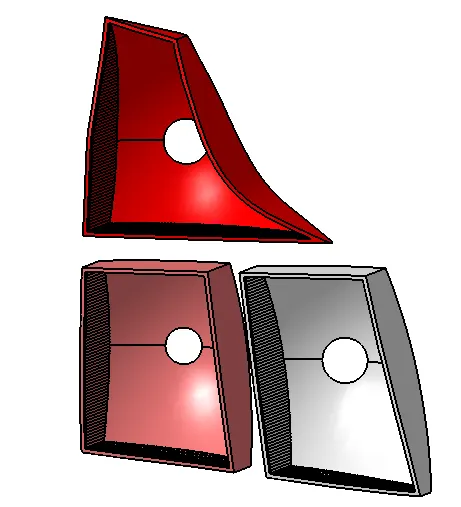
The reflectors are created with suitable flutes to avoid the bad reflection of the light . The focus of the reflector are made as 25 at inital stages and further increased based upon the geometrical visibility of the Lamp.
For Tail function bulb details:-
For tail function, P5W can be used (pin type with 5 watts)
For Stop function bulb details:-
For tail function, P21W can be used (pin type with 21 watts)
Mainly tail and stop function, OEM used to keep in same chamber most of the time so P21/5W (dual filament bulb) is being used
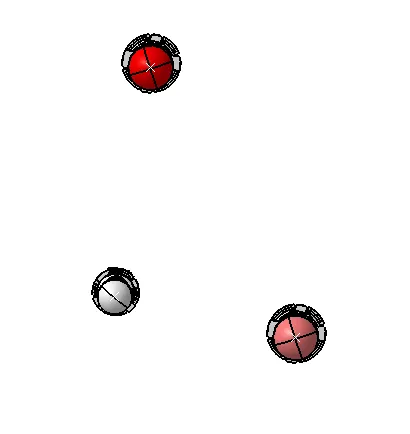
Once the housing reflectors are done the bulbs are moved to the respective positions with the Bulb socket.The input mounting features are given as below.
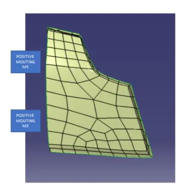
A suitable mounting scheme must be created for this in our housing to incorporate the mounting of the lamp.
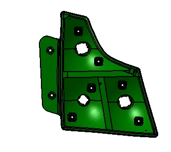
Once the Housing is done with the help of the surrounding data provided we are going to make a cord assy that can fulfill all the functions of the lamp.Proper clips and wires should be selected with the help of the PJM & Purchase department.
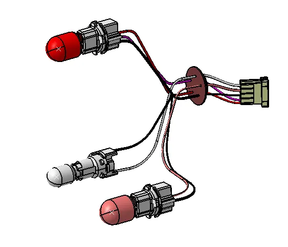
Once all the parts are done in design stage various analysis are done with the part so that the part can withstand the environment.
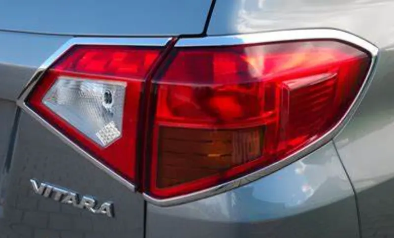
Sample rear lamp combinational lamp in Vitara brezza for comparison.
Exploded View
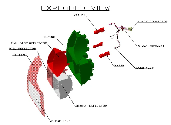
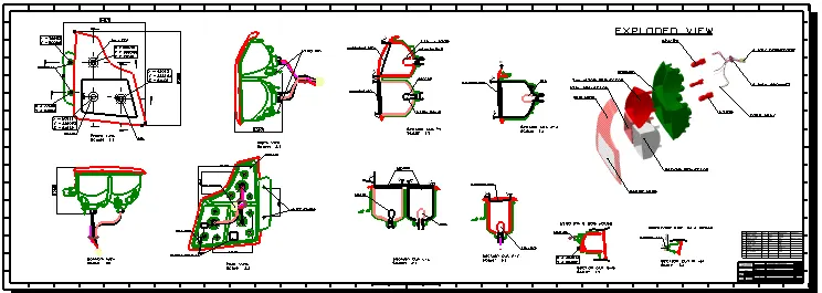
Assembly drawing
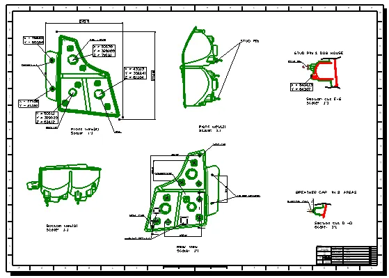
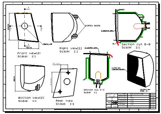
Housing Drawing
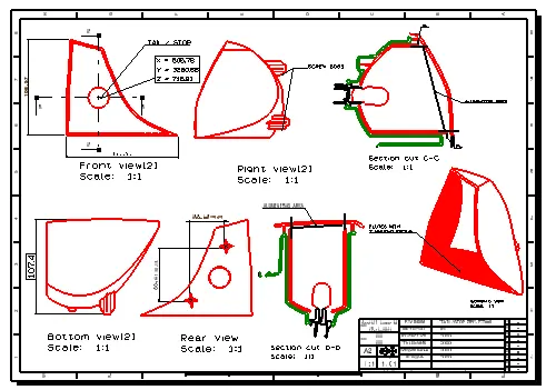
Reflectors
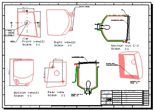
Conclusion
Various parts of an automobile lamps are created in accordance to the regualtions and an proper aseembly is made in CATIA. The parts are then drafted so that it can used by other teams to verify the quality of the parts in the assembly line.