Project 2
PROJECT 2
Aim :- Design and develop the Wiring harness on given backdoor and prepare flatten view drawing in CATIA V5. Application of all Packaging rules, Industry best practices studied in this course shall be demonstrated in design.
Introduction :- A wire harness, also commonly referred to as a wiring harness, is an exterior sheath used to cover some types of electronic wires. Generally, wiring harnesses are made of thermoplastic or thermoset materials that can help protect the cables from the environment.
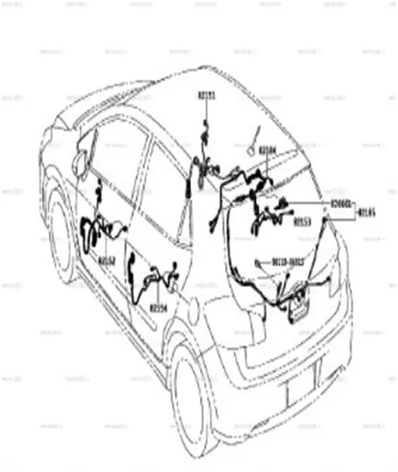
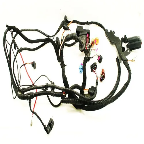
An backdoor wiring harness is constructed wires, cables, terminals, and connectors controlling a vehicle’s electrical system. It relays electrical power and control information to components such as batteries, alternators, fuel injectors, fuses, audio systems, blower motors, fuel injectors, and computers. Wire harness companies customize it for every location, application, and design it interconnects. Also known as a cable harness, it is more than just a collection of multiple wires put together.
It manages the key functions around the engine including engine controller, oil controller gate, transmission plug housing, air pipe sensors, pressure sensors, and water temperature sensors.
An engine wiring harness is how each part of your vehicle gets electricity. It is crucial to help the vehicle run and it’s usually made of a heat-resistant rubber to handle the high and low temperatures that vehicles often experience. The vehicle needs more than the engine, and it requires a lot of electricity for certain things to function, like the radio or lights. Beyond that, battery, starter, and even alternator run on power, which is provided by the engine. Without an engine wiring harness, we couldn’t start your vehicle.
How Does the Backdoor Wiring Harness Work :-
There are many cables in the backdoor wiring harness that work to connect electricity to your vehicle parts. This vehicle part has many sensors, and they work to ensure that everything in your vehicle is in working order. Some of these major systems in your car are fuel and transmission.
Think of this part of the vehicle like the brain. Without it, it wouldn’t be possible to get the information your vehicle needs. It’s always working overtime to relay the data your vehicle needs to function correctly. Whenever a sensor goes off, it’s because the engine wiring harness alerted the sensor of the problem.
The exciting thing is that as vehicles get more advanced, the backdoor wiring harness grows. Some say that new cars have over 100 pounds of wires, so imagine how many things could go wrong with that. In the past, there may not have been many issues. However, as things advance, there are more to go wrong.
Objective :-
- Define all the mechanical connectors electrically and save it in the Catalogue.
- Place all the connectors to the required positions on the given backdoor 3D CAD model.
- Create the Wiring Harness Routing with all the electrically defined connectors and mounting equipments.
- Create branching points at required locations to create sub branches and connect to various connectors in the geometrical bundle.
- Apply Protection coverings as required.
- Create Wiring harness flattening for the final geometrical bundle.
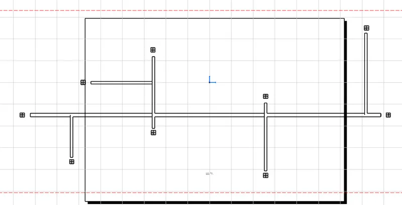
- Using the drafting workbench, create a drawing sheet with the flattened wiring harness.
Design Methodology :-
Step 1 :- download the backdoor CAD data and required connectors CAD data from the given source.
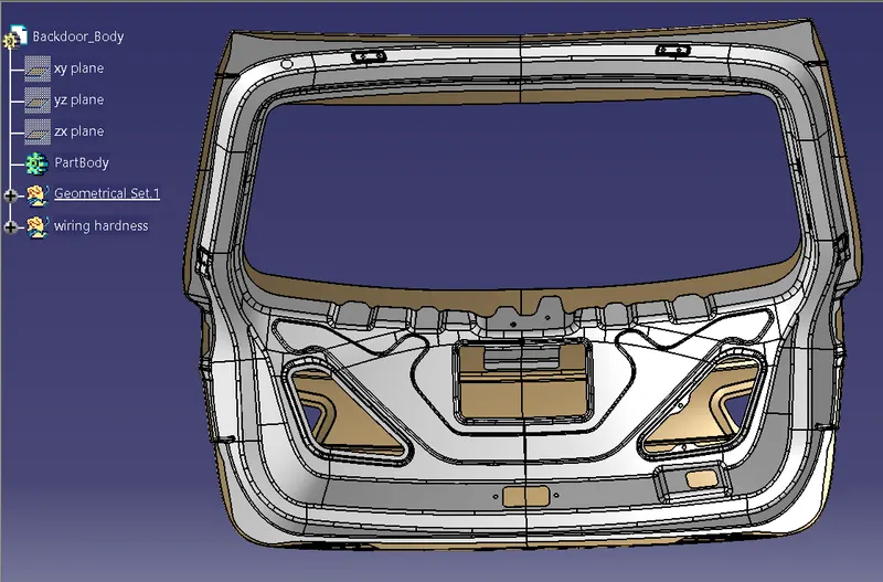
Step 2 :- Download the required Connectors from the source and convert the mechanical connectors electrically by using the electrical part design work bench by following below steps.
- First download the connectors and mounting clip from the given link source.
- Get into the mechanical part workbench to create required geometrical parameters. Create connector connection point and bundle connection point on the required sides of the CAD part.
- Create axis system on the connector connection point such a way that the Y coordinate facing normal to the connector face, X coordinate facing towards the locking mechanism and Z coordinate facing to the top.
- Create cavity connection point for connectors having the cavity for mounting clips
Using the geometrical parameters created,
- Define part as electrical connector.
- Define bundle connection point.
- Define connector connection poin
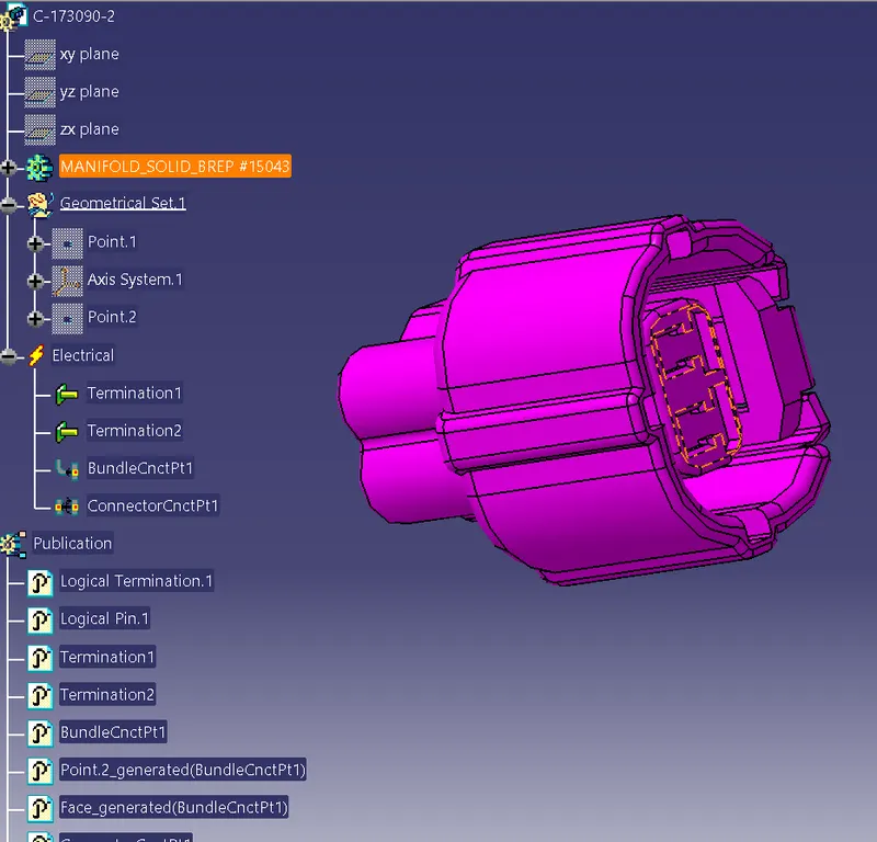
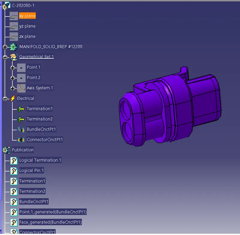
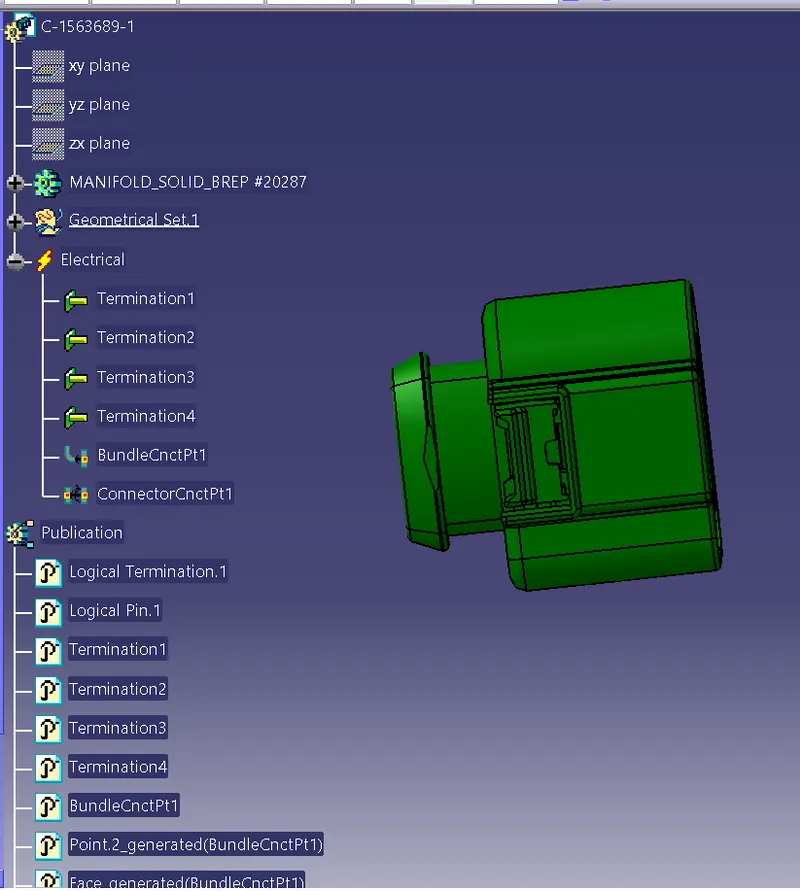
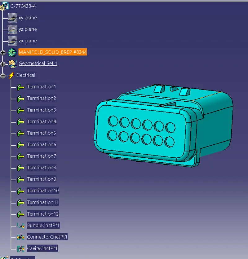
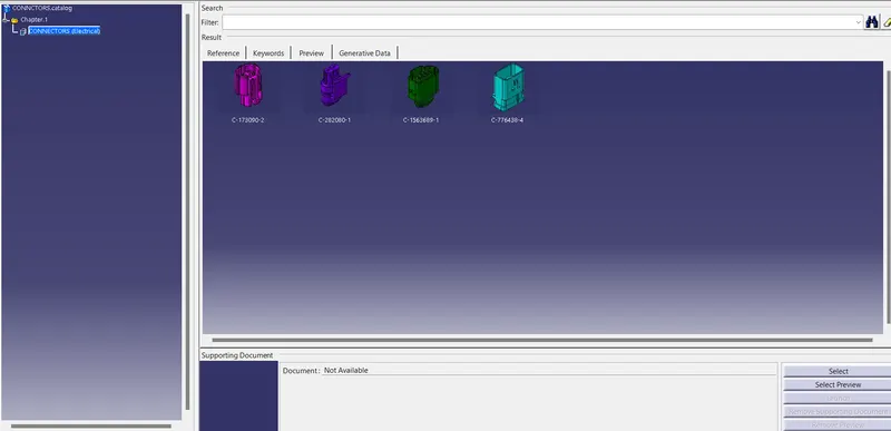
Adding Connectors to the Catalogue
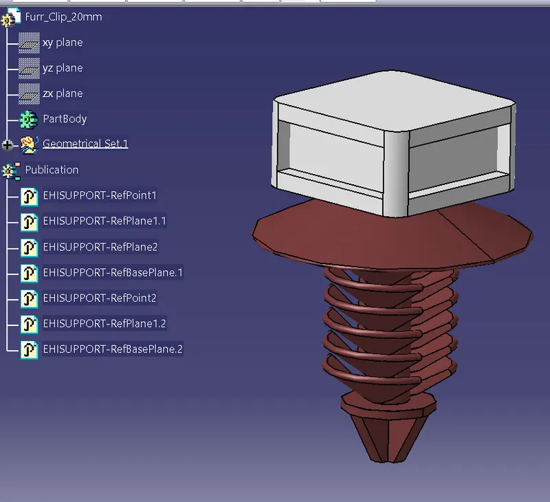
Furr Clip 20mm :-
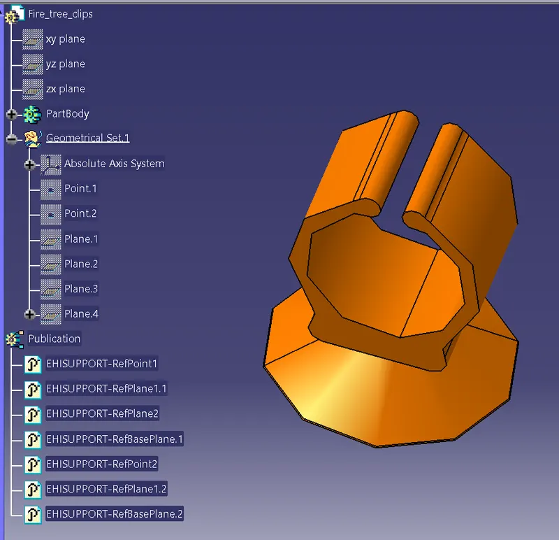
Fir Tree Clip :-
Step 3 :– Creating the context assembly
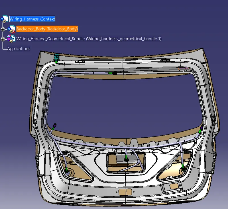
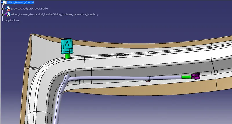
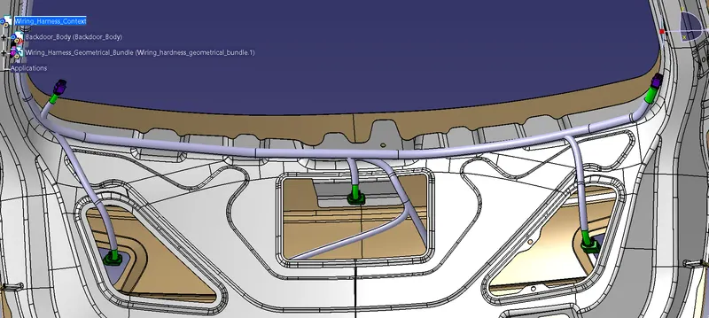
Context assembly is nothing but the product file which contains the backdoor 3D-CAD data and the backdoor harness geometrical bundle. Here the geometrical bundle product contains all the connectors and other mounting equipments, clips and clamps which are electrically defined for the assembly.
Design criteria followed to route the wiring harness :-
- Wiring harness routed by considering the factors ease in manufacturing, accessibility, easy removal and easy maintenance of attached equipments and routing harness.
- Wiring harness should be routed in such a way that it is easy to assemble on a vehicle.
- Wiring harness should be kept away from sharp environments like sheet metal brackets, panel edges, corners etc.
- Avoid harness routing and clipping in blind zone of operator during harness during installation.
- Ensure that routing meets the clearance requirements with the different surrounding parts.
- Routing shall provide enough slack for each branch to avoid additional stress on wire and terminal crimping joints but ensure that extra slack does not cause wiring harness foul with surrounding parts and impact desired clearance requirements.
- Enough clamps should be provided to ensure the positive clearance with surrounding and safety of wiring harness.
- Use of plastic guided channels are recommended to meet the clearances in critical areas if it is difficult to achieve by use of clamps.
- Minimum distance between clip and nearest branching point should be 25mm.
- Minimum distance between two breakouts should be 50mm.
- Ensure that harness protection is provided according to surrounding temperature, manufacturabilty and expected reliability.
- The min. bend radius is to be 1.4.
Bundle continuity :-
- In this step, first we have to make sure that multi-branchable is selected then we have to go in Edit>Search>Advanced>Workbench-Electrical>Type-Bundle Segment>Attribute-Fully Connected
- By selecting 'True' option will show all the connected bundle segments while selecting 'False' option will show all the non-connected bundle segments.
- Here, we have selected for the 'True' option and searched for results. All the bundle segments are highlighted found showing that all the bundle segments are electrically.
- In this step, first we have to make sure that multi-branchable is selected then we have to go in Edit>Search>Advanced>Workbench-Electrical>Type-Bundle Segment>Attribute-Fully Connected
- By selecting 'True' option will show all the connected bundle segments while selecting 'False' option will show all the non-connected bundle segments.
- Here, we have selected for the 'True' option and searched for results. All the bundle segments are highlighted found showing that all the bundle segments are electrically.
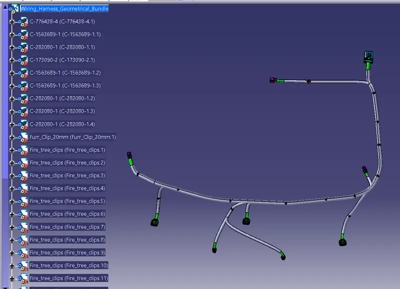
By using protection covering tool we protect the entire bundle. We have created a catalogue and we add the protection cover of 15mm diameter and 10 mm diameter. Here we Create a gap from the end and start extremity.
Step 4 :- Create Flatten View
Now we open a new product file for the Electrical harness flattening. Here we save the already made geometrical bundle segment and we extract the geometrical bundle to flatten harness by apply flattening parameters we flatten the geometrical bundle.
Once the branches are flattened we do some modification in the branches using the rotate, bend, and straighten etc. tools in the Electrical harness flattening.

Step 5 :- Creating a Flatten View Drawing