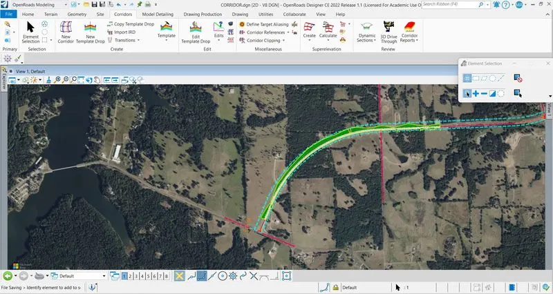
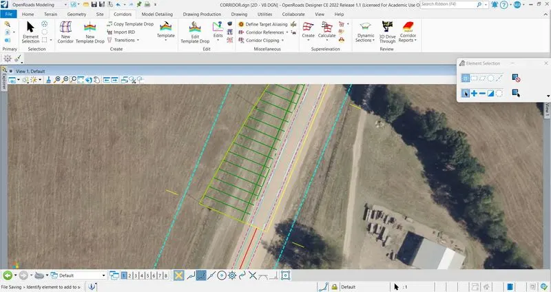
Project 2
- Existing 2 lane undivided rural highway of 11’ travel lanes + 4’ shoulder. Typical cross slope is 2.0%
- Speed of 50 MPH, rolling terrain, major arterial category of the highway remains the same.
- Proposed condition – existing 11’ lanes to be made 12’. Adding 1 center turn lane of 12’ and paved shoulder of 10’.
- End conditions of cut/fill/ditch – 1:6 preferred and 1:4 desirable for front slope and 1:4 preferred and 1:3 desirable for back slope.
- Entire typical cross slope to be maintained at 2.0%
Create a file named as "TERRAIN" with 2D SEED > Click on Attach Tools > References > Attach Reference > Reference the ROW_EXIST and ROW_PROP > Click on fit view.
Click on Utilities > Click on Co-ordinate system > From Library > Add TX83-NCF-NAD83 > Click on View Attributes > Select Background Map Type : Aerial > Click on screen > Aerial Map is opened.
Open Attach Tools again > References > Set the scale to coincide the drawing with the map.
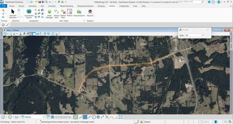
Again click on Attach Tools > References > Attach Reference > Reference TERRAIN FROM FILE > Set the scale for TERRAIN FROM FILE.
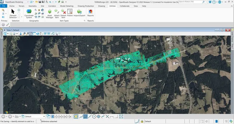
Create a file named as ALIGNMENT AND PROFILE with 2D SEED > Reference the ROW_EXIST and ROW_PROP > Set the co-ordinate sysytem > Set the scale for reference file to coincide the drawing with map.
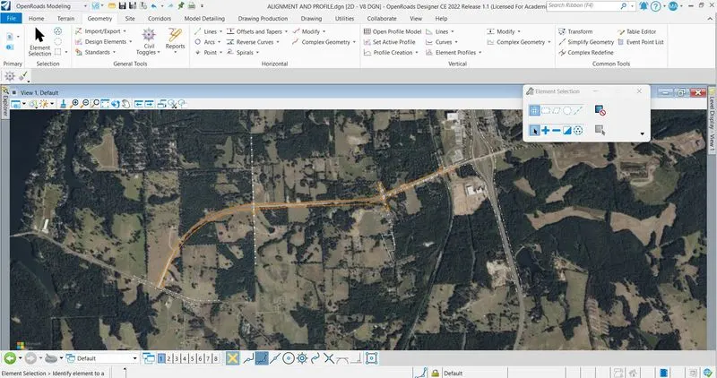
Click on Geometry tab > Lines > Line Between Points > Select the start point and end point with Feature Defination of Geom_Baseline > Do the same where the line required.
Click on Arcs > Arc Between Elements > Simple Arc > Select the first line and second line where the arc is required > Set the radius and Feature Defination > Arc is installed > Click on Complex Geometry > Complex By Element > Locate First Element > Set the method and Feature Defination > Complex element is created.
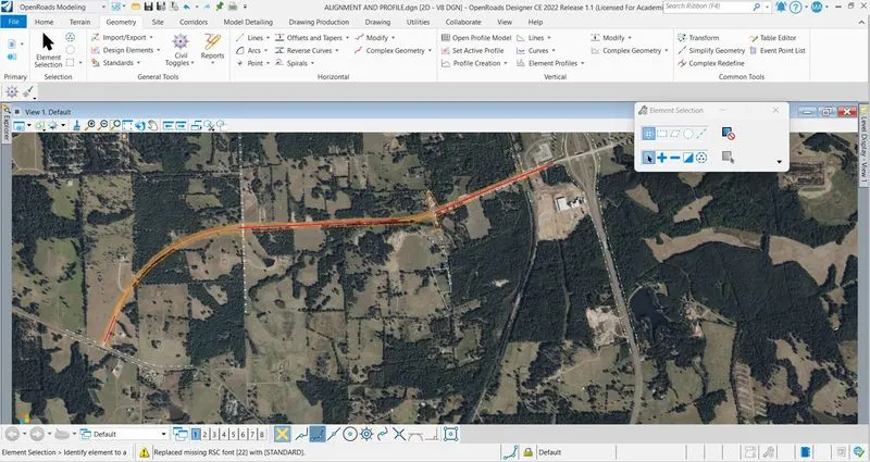
Reference the TERRAIN FROM FILE > Set the scale to coincide with map > Click on Terrain tab > Active > Set active > Select the Terrain Model > Click on Geometry tab > Click on Open Profile Model > Select the plan element > Select the view tab > Existing ground profile is created.
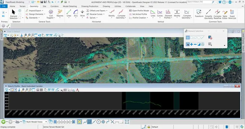
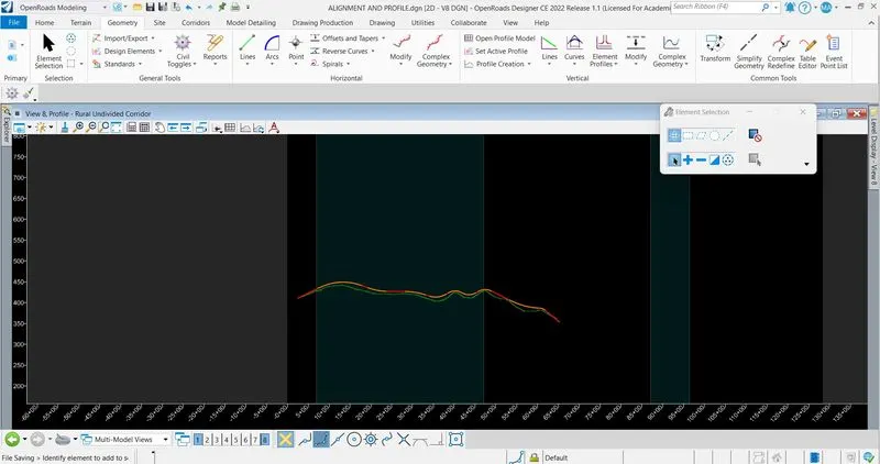
By Vertical Geometry, we created profile by layout > Create profile by lines and curves and made it complex > Set it active by clicking on lineand hover on it and activate it.
Create a new file named as "RIGHT OF WAY" with 2D SEED > Reference the ALIGNMENT AND PROFILE, ROW_EXIST, ROW_PROP > Create the alignment for intersection by horizontal geometry > Create offset for mainline alignment > By Horizontal Geometry, fix the right of way at intersection > CReate 2 lanes Undivided Rural Highway.
Edge of Pavment = 11'
Shoulder = 4'
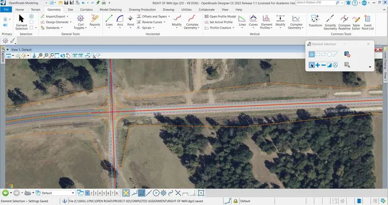
Create a new file named as CORRIDOR with 2D SEED > Reference the TERRAIN FROM FILE, ALIGNMENT AND PROFILE and RIGHT OF WAY FILE > Set the terrain model as active.
Click on Corridor tab > Click on Template > Create Template > Create a new Folder and two Template named as EXISTING and PROPOSED.
In EXISTING :
2 Lanes - 11'
3 Layers - Top layer = 0.4'
Intermediate Layer = 0.7'
Bottom Layer = 1'
Shoulder = 4'
In PROPOSED :
2 Lanes - 12'
3 Layers - Top layer = 0.4
Intermediate layer = 0.7'
Bottom layer = 1'
Shoulder = 10'
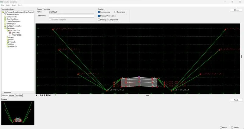
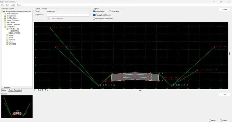
Click on New Corridor > Locate Corridor Baseline > Set the Feature Defination > Corridor is created.
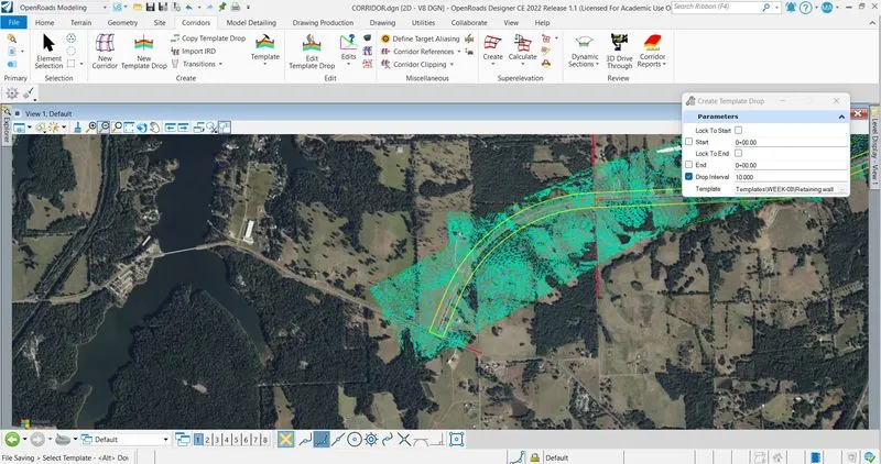
Create Template Drop > Select the Template (EXISTING) > Select the start point and end point > Select the drop interval > Template drop is created.
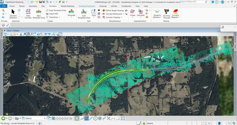
Click on Template Drop > Properties > Change the template from EXISTING to PROPOSED > Template is set for PROPOSED.