Project 1 _Creating an Architectural plan for the provided plot size and develop relevant basic structural drawings
Project 1: Creating an Architectural plan for the provided plot size and develop relevant basic structural drawings
Aim:Design and Draft a layout of a residential building with the following details:
- Plot Size: 60’x20’(18.3m x6m)
- Orientation- Facing East
- Develop the following: 1. Architectural Drawing (Floor Plan, Elevations, and Sections) 2. Structural Drawing (Column, Bean, Footing Plan)
Procedure:
The residential building to be drawn with plot dimensions 60’X20’.The G+1 floor is designed with stairs outside. The plot is east facing. The building is designed with following rooms
Ground Floor:
- Living Room
- Kitchen (Open)
- Dinning
- Bedroon(2)
- Store Room
- Staircase to first floor
First Floor:
- Living Room
- Kitchen (Open)
- Dinning
- Bedroon(2)
- Store Room
- Staircase to Terrace
- Balcony.
Below are the dimensions used:
Walls:
- Thickness of outter walls is taken as 9”
- Internal wall thickness is taken as 6”
Columns and Beams:
- All the columns are of size 9”X18”.
- All the beams are of size 18”X18"
Doors:
There are three door types
- Dimension of Main entrance sliding door is 8’X8’.
- Dimension of doors of all bedrooms are 3’X8’
- Dimension of doors of all toilets and store room are 2’6”X8’
Windows
- Windows W: 6'X4’.
- Windows W1: 2'x3'.
- Windows W2: 3'x4'
Staircase:
- Thread and Raiser are taken as 1' and 6” respectively.
STEPS:
Open AutoCAD
In Start-up settings start from scratch select Imperial (Feet and Inches)
Type ‘un’ in command box and press enter
Change units’ type to decimal and precision to 1’1/16” and insertion scale to inches
Step 1: Creating Layers
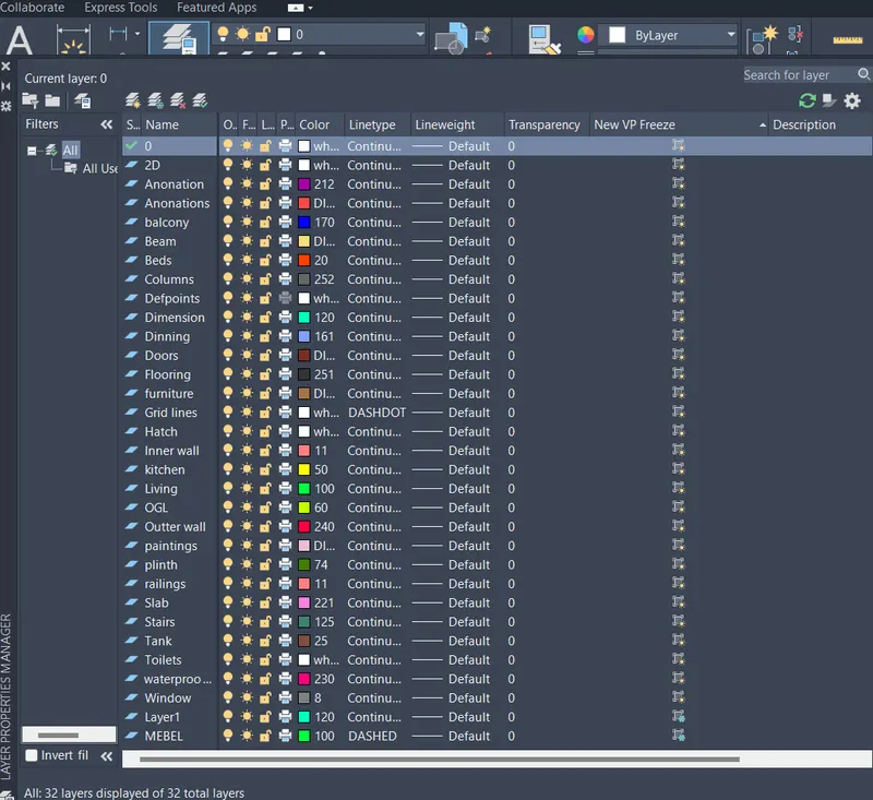
Open Layer properties and create new layers by clicking on new layer or right click on any layer and select new layer to create new layer
Layers are created as follows
Step 2: Creating Ground Floor Plan View
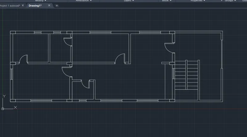
Change the current layer to wall layer
- Draw a rectangle of dimensions 60’X20” at any point on the screen
- Draw the Walls by using Offset Commands of 9" and 6" respectively.
- Draw the bedrooms, living, kitchen, store, toilets by using offset commands.
- Create a column of 9" by 18" and place it at the required locations.
- Now trim the unwanted lines.
- Now create a lock of doors and windows and place it at the required locations.
- Draw the Stairs and provide the R:6" and T:1'.
- Draw the kitchen Slab of 2'.
- Create a dynamic blocks of doors and place it at required locations.
- Annonate the respective rooms.
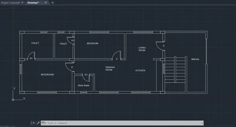
- Provide the respectives layers to every components.
- Insert every components required for the plan from the adc command i.e design center.
- Design center command is used add home furniture, kitchen equipment, and plumbing equipment for the rooms.
- you can also downloads various designs of furniture, kitchen equipment, and plumbing equipment for the rooms for the various websites and use it as you like.
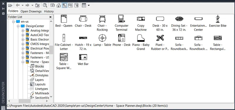
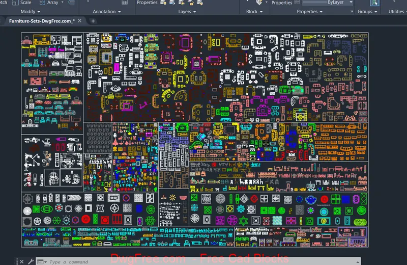
Some addition furniture is imported from another file from the internet called ‘mubles’
Furniture added from both is
- Dining Table
- Sofa
- Kitchen
- Bed-Queen
- Toilet W/c
- Bathtub.
- Doors.
- In the end dimension it properly.
Result of Ground Floor Plan 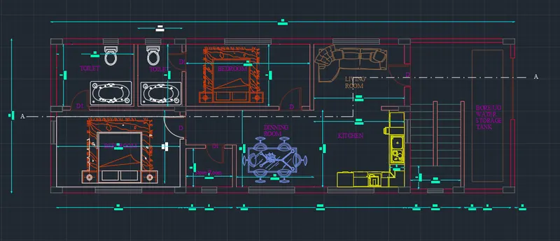
Step 2: Creating First Floor Plan View
- My ground Floor and 1st floor are mororless same except the balcony.
- i have a balcony in place of bore/ug water storage on the first floor.
- Copy the Ground Floor plan and Annonate the balcony.
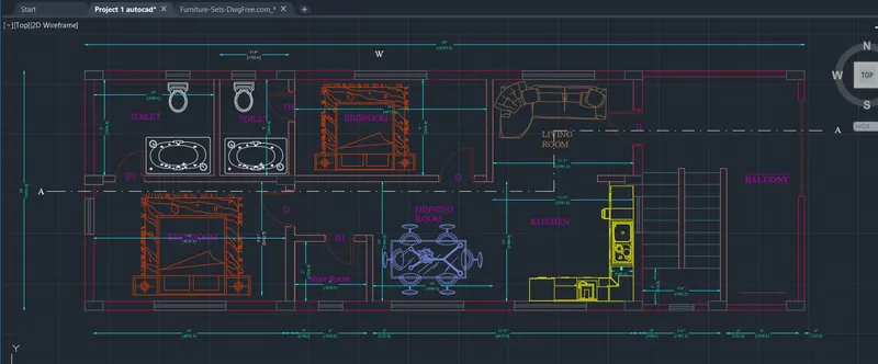
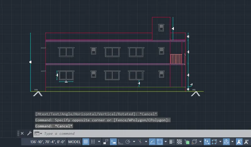
Step 3: Creating Elevations
- Change the current layer to extension lines
- Create vertical extension line at all the wall edge points
- Draw all the wall with their thick
- Trim the extra portion
- Doors and windows for elevation.
- Floor to Floor height is 10' draw it by using offset.
- Draw the projected chajja by line command.
- Drwa the plinth level by line command.
- Draw te ogl by line command
- Provide it at the respective layers.
- Dimension it.
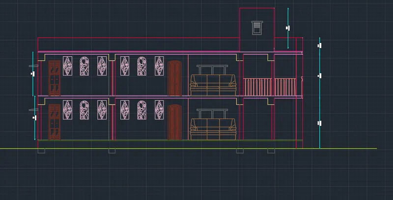
Step 4: Creating Section Views A and A
- Change the current layer to extension lines
- Create vertical extension line at all the wall edge points
- Draw all the wall with their thick
- Trim the extra portion
- Doors and windows for elevation.
- Floor to Floor height is 10' draw it by using offset.
- Draw the projected chajja by line command.
- Drwa the plinth level by line command.
- Draw te ogl by line command
- Provide it at the respective layers.
- Dimension it.
- Provide the beam and Column size.
- provide the railings by using line or block commands
Step 5: Creating Other Drawing layouts
- Column Layout
Change the current layer to wall layer
- Draw all the walls of the plan view excluding doors and windows
Change the current layer to column layer
- At the bottom left corner draw a rectangle using column layer
- All the columns are of size 9”X18”.
- Columns are placed along the direction of wall in some cases
- Draw the columns at all necessary points
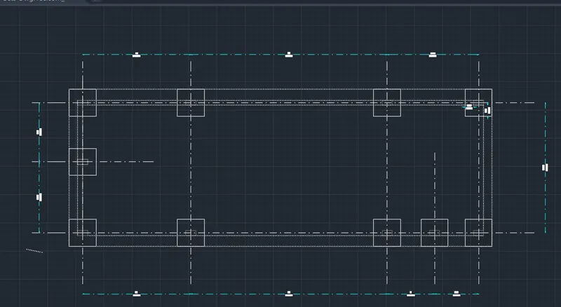
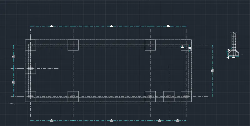
The column layout for the G+1 residential house is as follows
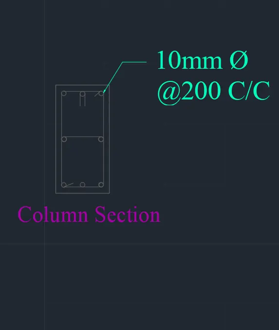
- Reinforcement in column consists of 8 bars of diameter 10mm.
- Stirrups of 8mm dia bars with 200mm center to center spacing
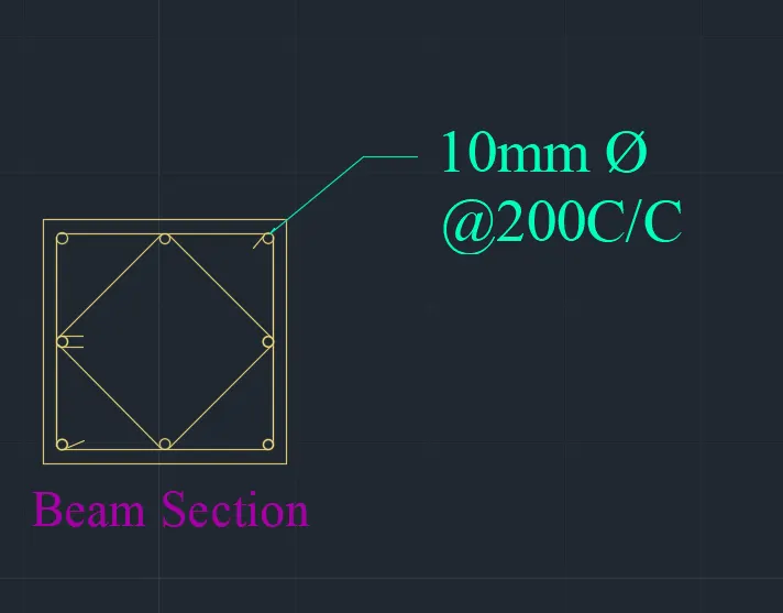
The Beam layout for the G+1 residential house is as follows
- Reinforcement in column consists of 8 bars of diameter 10mm.
- Stirrups of 8mm dia bars with 200mm center to center spacing
Result:
Commands Used in this challenge
- Line
- Xline
- Polyline
- Rectangle
- Circle
- Arc
- Trim
- Move
- Offset
- Hatch
- Layer
- MatchProp
- Multileader
- Fillet
- Copy
- Explode
- Dimlinear
- Dimcontinue
- Dim break
- Dim update
1. Floor plan: 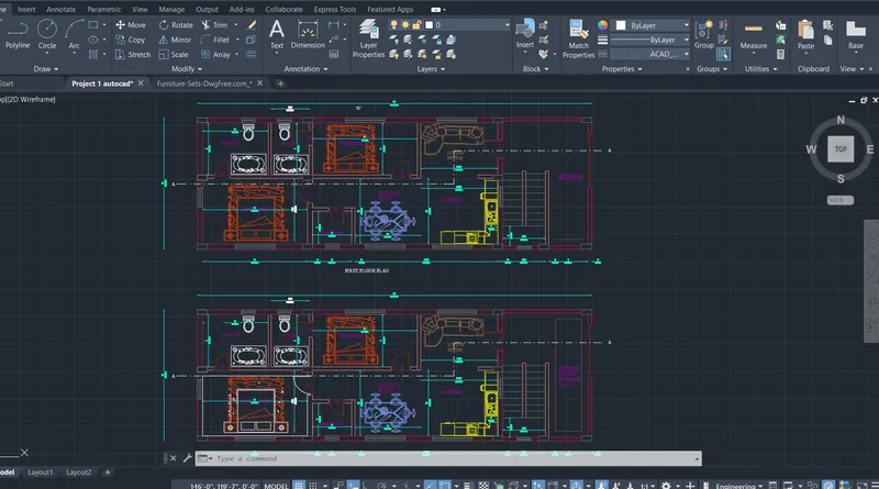
2. Elevations: 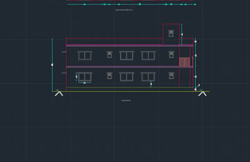
3. Section: 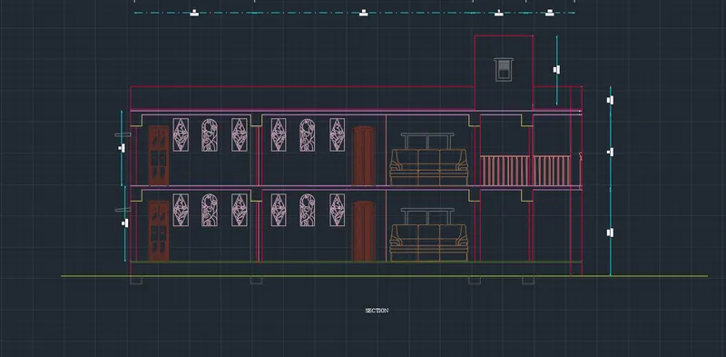
4. Column: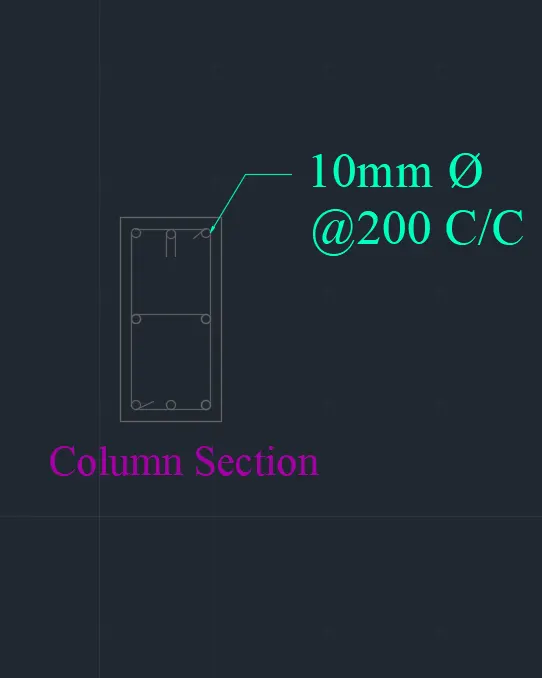
5. Beam: 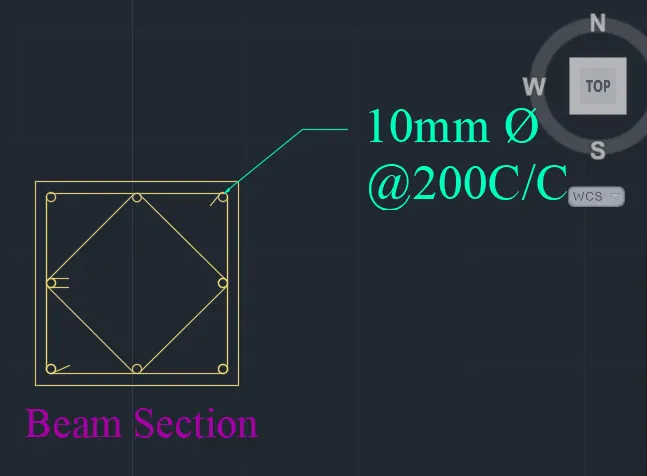
6. Footing Plan: