Project 2
BACK DOOR WIRING HARNESS
AIM:
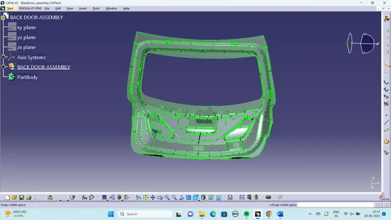
To Route the Wiring harness on Given car body and prepare flatten view drawing in CATIA V5. Application of all Packaging rules, Industry best practices shall be demonstrated in design. Apply Protection coverings as required.
BACK DOOR:
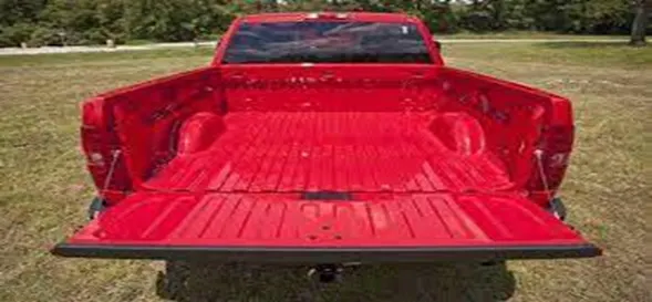
A door is a hinged part which is used for entry and exit of the vehicles. Back doors are one of the type doors of the vehicle which are located next to the passenger seat which provides access to the luggage compartment. In most of the cars, these back doors are operated with the help of gas stay which in turn reduces the effort required to lift open the door. Some luxury cars have powered backdoor which in turn is driven by an electric motor. This kind of system is also called a powered trunk lid system. Hatchback or station wagons are sold as 3 door or 5 door models. In this case, the rear hatch is classified as door this is because it enters the passenger compartment. The naming is mainly used in Europe countries. In case of safety, the back door designed should meet the safety requirement for the rear collision.
TYPES OF BACK DOOR:
- TOP MOUNTED DOOR
- SIDE MOUNTED DOOR
- BOTTOM MOUNTED DOOR
TOP MOUNTED DOOR:
This type of back doors is used in a station wagon, pickup truck and some of the sport utility vehicles. Today’s modern cars use top-mounted tailgating systems which are both powered and also gas stay supported. These top mounted tailgates provide greater rear visibility compared to side-mounted or bar doors which have canter pillars in it.

SIDE MOUNTED DOOR:
It is generally used in van type MPVs, SUVs, pickup truck vehicles. These side mounted door/barn doors are a lot easier compared to top mounted ones. These doors are generally small in size and can be easily accessed. These doors are more convenient for the goods handlers carrying lengthy objects, long pipes where one door is kept open. It also saves accidental head impacts. It is a lot easier to load /unload things in vehicles having side-mounted doors.

BOTTOM MOUNTED DOOR:
Bottom type or split type backdoor system is used in estate type cars, pickup trucks and some luxury SUVs. These are most convenient type of backdoor in which the bottom split is used as a support or even as a table for the touring people.
GIVEN DATA:
PACKAGING RULES AND ASSUMPTIONS MADE IN THIS PROJECT:
- Avoid harness routing and clipping in a blind zone.
- Avoid harness routing through the small structural holes and openings to minimise the chaffing and handling of the wiring harness during installation.
- Provide additional slack to the harness according to the surrounding and harness bending requirements. And avoid excess slack to the harness.
- Provide sufficient clearance to the different surrounding parts.
- Avoid routing over the bolts, near to the bolted joints or screwed joints. Because it may damage the harness or may puncture the harness.
- Avoid routing near the sharp edges like thin sheet metal brackets, panel joints, etc.
- Provide at least 100mm clearance to the harness from the ABC pedals, clutch lever & cables, Engine timing belt or any other dynamic components.
- Enough clips and clamps should be provided to ensure the positive clearance with the surrounding and safety of the wiring harness.
- Ensure distance between two clamps on a straight branch should be maximum of 200mm.
- Clamping requirements should be decided based on the harness bending, surrounding and mounting arrangements.
- Provide positive clamping at the engine and chassis to avoid the harness damage when Engine rocks.
- Keep harness away from the transmission dynamic assemblies like drive shaft or propeller shaft.
- Provide the guiding channel if it is required.
- Use the rubber gromets which provide the proper sealing, and also protects the harness from the sharp edges and absorbs the vibrations.
- Wiring harness minimum branch length should be 50mm.
- Minimum distance between the clip and nearest branching point should be atleast 25mm.
- Minimum distance between two breakouts should be 50mm.
- Limit the number of branches coming out from the single branch to 4.
- Provide the bracket for the interconnection connector parking.
DEFINE CONNECTORS:
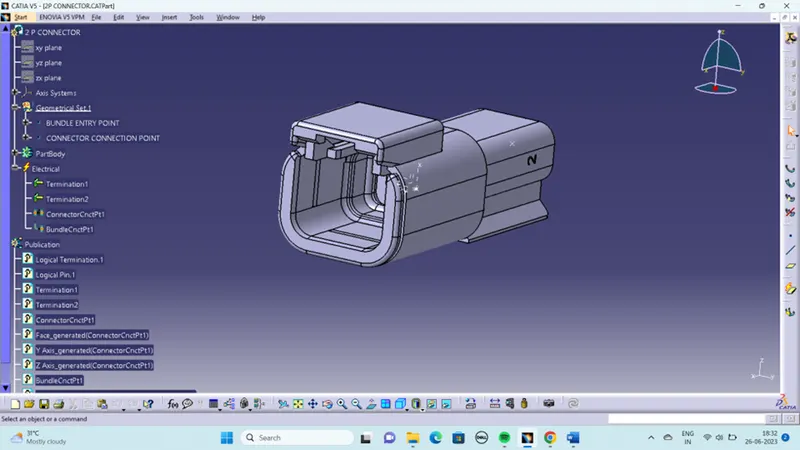
open the cad data of connectors in Catia part design workbench and create the connector connection point, connector connection axis system, bundle connection point. Then Switch to electrical part design workbench and define it as a connector also define connector connection point and bundle connection point. Here we have interconnection connector it requires mounting clip for mounting the connector .so cavity connection point should be defined for this connector. All the connectors defined as electrical connector and defined all the necessary properties to Connectors. Created a catalogue document in connector family and stored all the connector data in catalogue document.
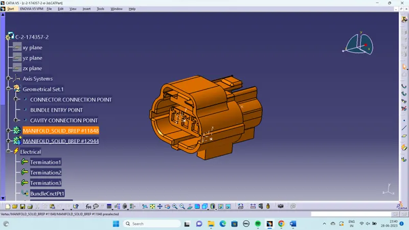
clips and clamps:
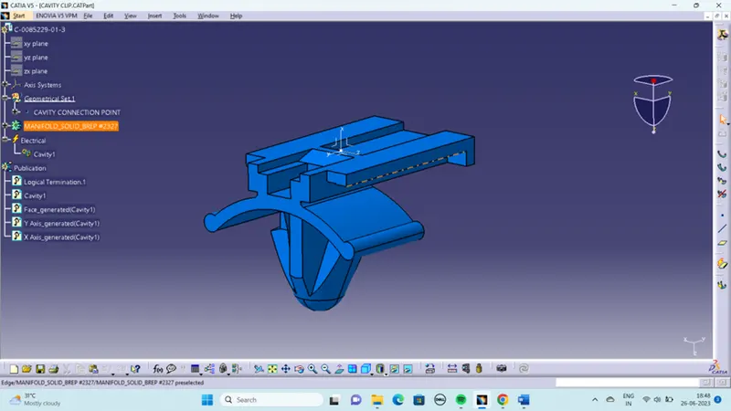
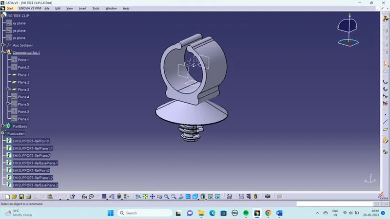
define the mounting clip electrically by defining all the properties. Define the clip as mounting equipment using mounting equipment command. Select cavity command and define the parameters.
CAVITY CLIP:
FIR TREE CLIP:
P CLAMP:
P-Clamp enables next generation assembly, quick installation, and a flexible and ergonomic design. P-Clamp is the new solution for “tool-free” harness installation in military, aerospace, marine, and industrial applications.
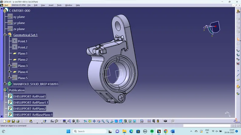
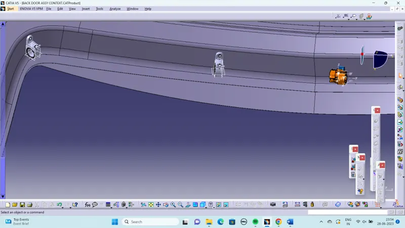
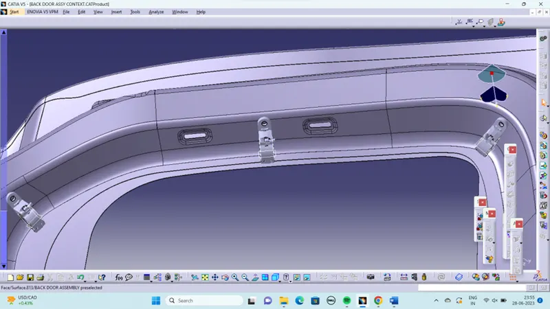
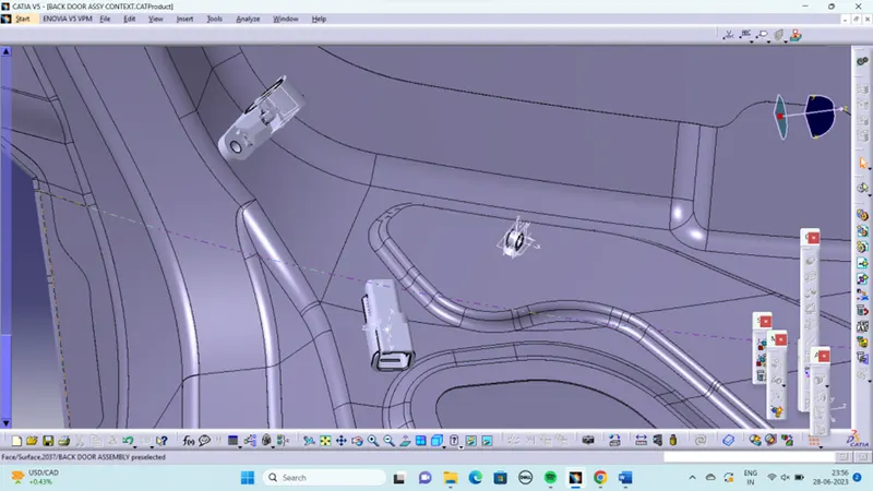
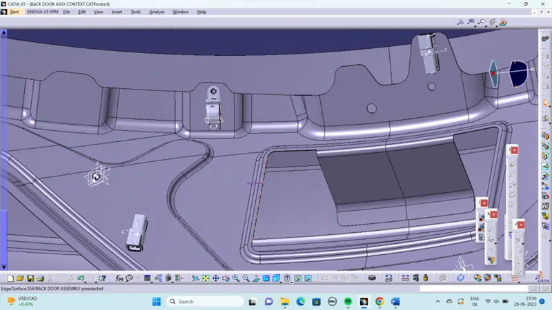
POSISTIONING OF CONECTORS CLIPS AND CLAMPS:
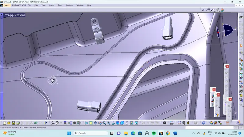
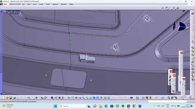
HARNESS ROUTING:
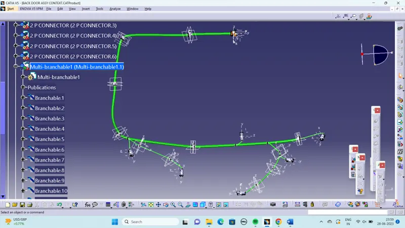
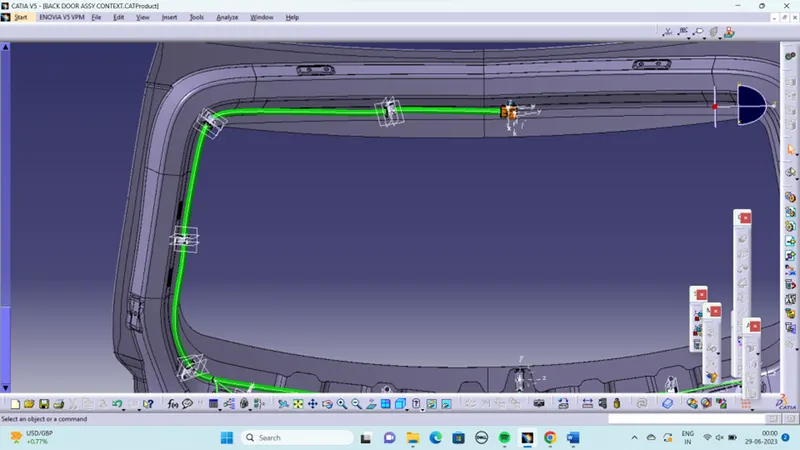
Add guiding channel for routing the wiring harness to the fuel injectors.it deals with clearance management and thermal protection of the wiring harness in the high temperature zones. Then request engine design team to provide additional threaded holes required to mount the guiding channels in proper location by using bolts or screws. After define the geometrical bundle electrically then select the multibranchable command to start the bundle routing and click on the route definition.
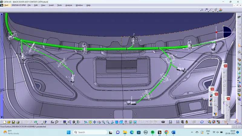
The bundle routing starts from interconnection connector and then to the P-clamps and to the guiding channels. Adding branches points to route the wiring harness from main branch to various connectors.
To route the wiring harness through the guiding channels, select external curve option and click on the line created in the guiding channel. Then add branch points to route the wiring herness from the guiding channel to the connectors. proper bend radius and slack provided for the bundle segment to avoid stress on the wire.
PROTECTION COVERING:
Add protective coverings on the wiring harness to protect wiring from high temperature. protective covering created by using define protection part command in the electrical part design workbench. Select part, and define the parameters as per the requirement.
The created corrugated tube can be added into the catalogue by store device command and selecting the catalogue file created for protective covering. then appropriate protective covering added to the bundle segments.
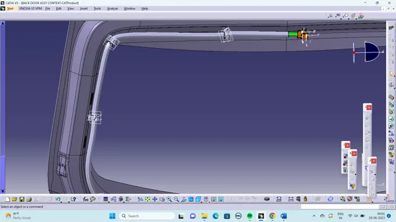
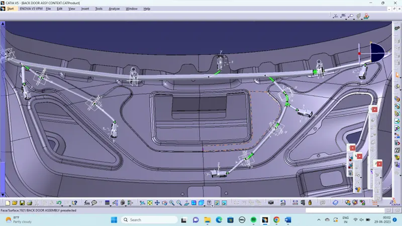
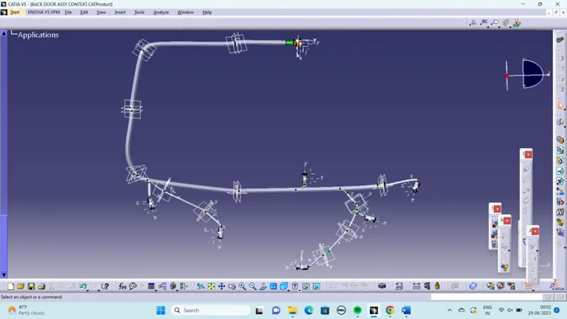
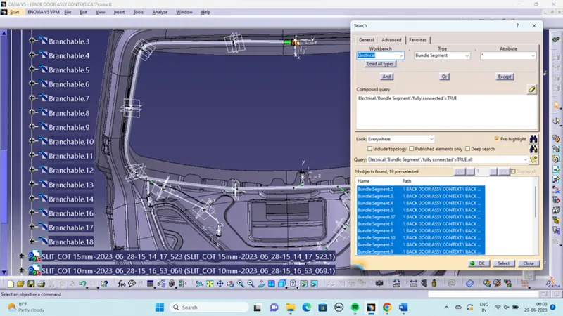
After the routing of harness bundle the I check the connectivity of the harness bundle.
HARNESS FLATTENING:
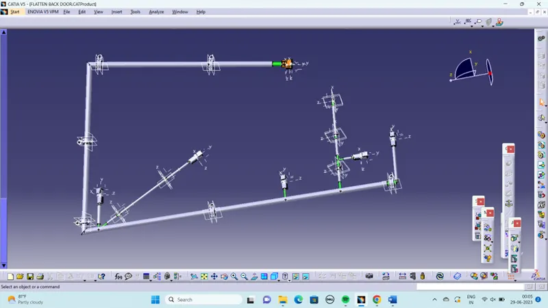
Create a new product file for flatten the wiring harness and save as in the same folder where the wiring harness is saved. Then switch to Electrical harness flattening workbench and select harness flattening parameters and define harness flattening parameters. Before creating flatten view, make sure that selecting 'Double line' for bundle segment and 'Double' line for protective covering.
STEPS TO FOLLOW:
- We go to the harness flattening workbench and define the flattening parameters.
- While defining the harness flattening parameters in the drawing menu single line is selected for bundle segment and double line is selected for protective coverings in order to differentiate between the wire bundle and cot tubes in drafting.
- We use the extract command to bring the harness assembly to the flattening workbench here.
- Then wire harness assembly is imported to the Wire flattening product file with 'EHF' extension added to the geometric bundle assembly name
- Choosing a suitable plane to flatten the harness assembly.
- Bundle segments are rotated at the required angles. The harness assembly is then drafted.
- Flattening parameters are defined in order to make the bundle and the corrugated tubes visible in the 3d drawings.
- Save the product file using 'Save management' option so that all the related product files and part files are stored in single directory.
DRAFTING:
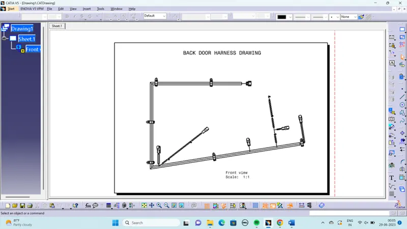
- Create a new drawing file and save the file in the same location.
- Add the front view of the harness assembly Here I select the surface of the connector. and orient the view as per the requirement.
- Go to the properties of the view and select the '3D Wireframe' on and ' Is always visible' option in order to see properly the Wire bundle, connectors and the protection coverings.
- Then Naming the connectors and cot tubes.
- To add the length details of the bundle segments.