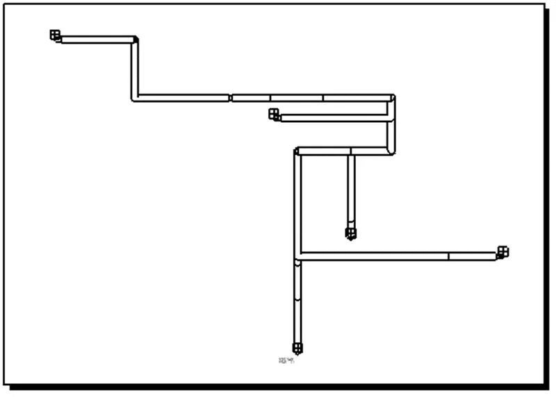
Project 2
Project 2: Designing a thorough Wiring Harness Assembly for a Car's Backdoor
Statement of Assignment:
Route the Wiring harness on the given car body and prepare a flattened view drawing in CATIA V5. Application of all Packaging rules, Industry best practices studied in this course shall be demonstrated in design. Apply Protection coverings as required.
Available connector 3D data can be used, or you can download the connectors from www.te.com
Prepare & Submit all necessary reports like clearance, Clipping/Clamping selection, Harness fixing requirements, Harness continuity, and Assumptions if any along with CATIA 3D data.
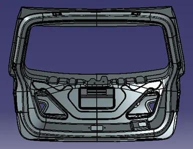
Back View
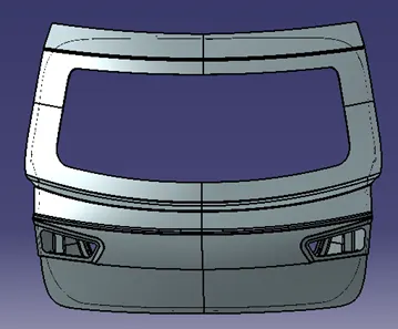
Front View
Problem Description:
- The front and back views of a car's backdoor are displayed in the images above, and a wiring harness needs to be made for it.
- There will be a wire harness made for the number plate light and the taillights.
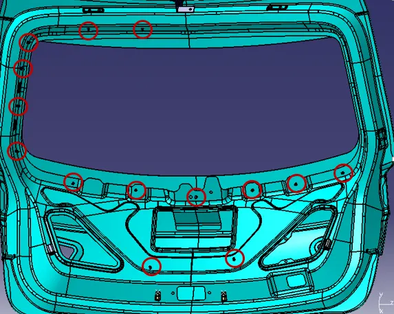
- There are two 2-pin connectors for the number plate light, two 4-pin connectors for the taillights, one interconnection connector, and 14 Omega clips for bundle routing
- The wiring harness starts from the interconnection connector, passes through the Omega clips, and ends in the 2-pole and 4-pole connectors
- All bundle segments should have a bend radius ratio of 1.4.
Background, Technical Specifications, and Assumptions
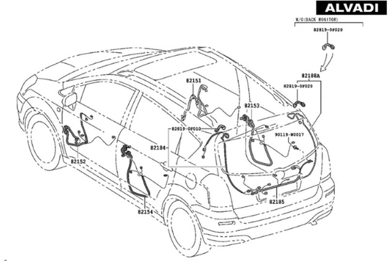
The following industry best practices and regulations regarding wiring harness packaging must be adhered to:-
- When designing the wiring harness, ease of manufacture, installation, removal, and maintenance must be taken into account.
- Avoid routing through tiny structural holes or apertures to reduce handling and chaffing during installation.
- When assembling or servicing a harness, avoid routing and clipping in regions that are difficult to access or in the blind zone.
- Provide additional slack when required according to the surroundings or the harness bending requirement. Slack values between 1% and 5% are used for this project.
- When designing the wiring harness in the CAD environment, it should be ensured that there are no instances of fouling. To prevent fouling, additional clips or clamps may be used.
- Protect the harness by avoiding routing it close to edges with sharp edges.
- There should be enough mounting tools like clamps and clips available.
- The branch length should be at least 50mm.
- A minimum of 25mm spacing should be kept between the clip and the branch point.
- There should be at least 50mm spacing between the two branch locations.
- The wire harness needs to be simple to assemble and access.
- To avoid paying extra costs for specialized mounting solutions, clips and clamps for the wiring harness should be easily obtainable on the market.
Step 1: Definition of Connectors, Mounting Clips, Brackets, and Supports
The following connectors are defined and used according to the application requirement:
- ‘C-776438’ which has 12 poles and is used as an interconnection connector
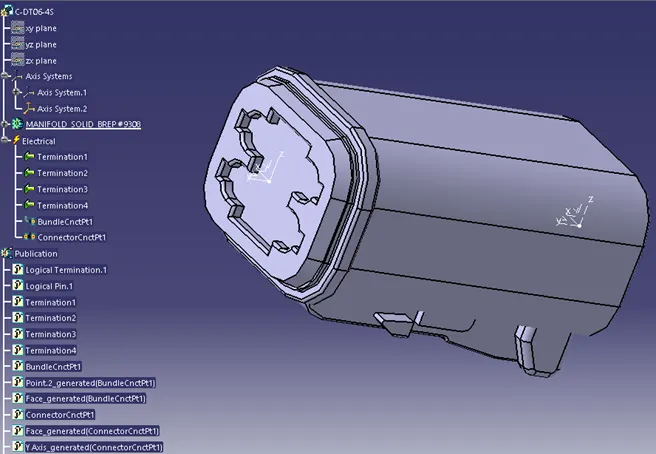
- "C-DT06-4S," which has 4 poles and is used for the taillight
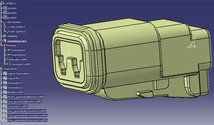
- "C-DT06-2S," which has 2 poles and is used for the number plate light.
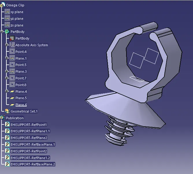
The CAD data was downloaded from te.com. In the "Electrical Part Design" workbench, we should first define the geometrical parameters such as the bundle connection point and connector connection point before we can electrically define a connector. Further, a mounting clip is defined and attached to the interconnection connector, and then they are both embarked on an L-sheet metal bracket. Additionally, Omega Clips are used as support and for routing the bundle segments. The Omega clips must be mounted on the backdoor in order to operate as a directing channel and support, so we must first specify it electrically with geometrical parameters, entry, and exit points on the left and right sides of the clips. Based on that, the aforementioned connectors, the interconnection connector, and the Omega clips are defined and prepared for the wiring harness and routing.
C-776438 (Interconnection Connector)
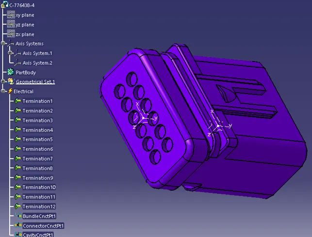
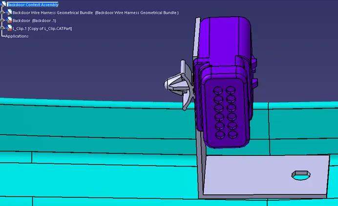
In addition to bundle and connector connection point, we should define the cavity point, so the interconnection connector can be mounted on a clip, and then parked on the L-sheet bracket.
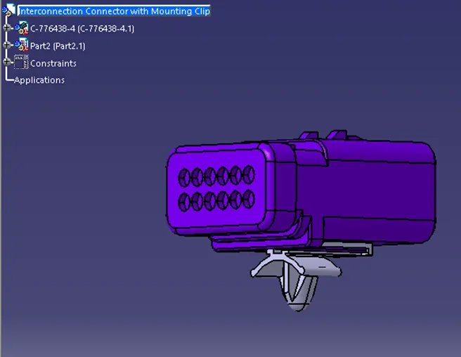
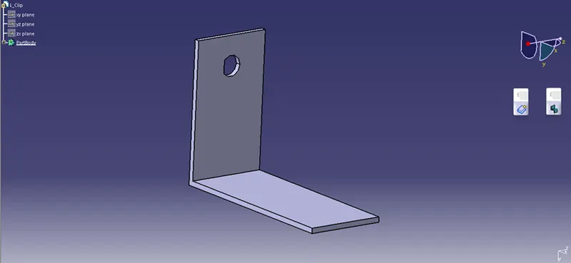
Sheet Metal Bracket
To provide parking for the interconnection connector, add L-sheet metal bracket. Additionally, we must ensure that the bracket is positioned outside of the backdoor and geometrical bundle assemblies and inside the context assembly.
C-DT06-4 (4-Pole Connector)
C-DT06-2S (2-Pole Connector)
Omega Clip
Step 2: Creating Context Assembly
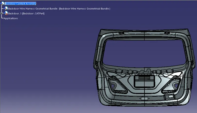
- The main assembly, as depicted in the above diagram, will be a Context Assembly for backdoor Wire Harness.
- Backdoor Wire Harness Geometrical Bundle Assembly and the backdoor body are parts of the backdoor Context Assembly.
Step 3: Placement of Connectors and Mounting of the Omega Clips
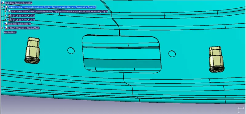
Place the interconnection connector with the attached mounting clip on the L-bracket
Place the 2-pole connectors in a suitable location for the number plate light
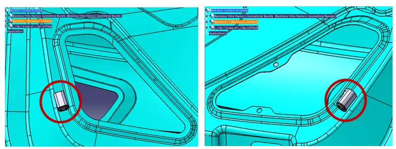
Place the 4-pole connectors in a suitable location for the tailpipe lights
Install the Omega clips to the backdoor to serve as a support and a channel for bundle guidance. The red circles show the location of the installed 14 Omega clips.
Step 4: Bundle Routing
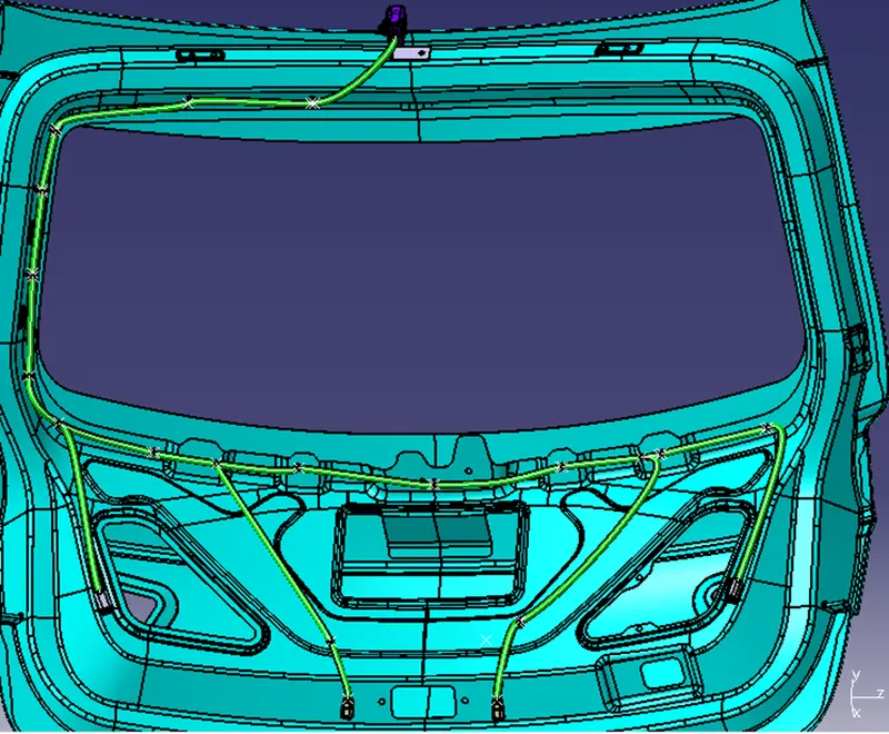
- The bundle segment is routed from the interconnection connector, through the Omega clips, up to the 2-pole and 4-pole connectors
- The ratio of bend radius is kept at 1.4
- The thicknesses of all bundle segments are 10mm
Step 5: Check for Bundle Continuity
Electrical Workbench Edit > Search > Advanced > Type: Fully Connected is a bundle segment attribute. When the attribute criterion's "FALSE" option is used, all of the related bundle segments are displayed.
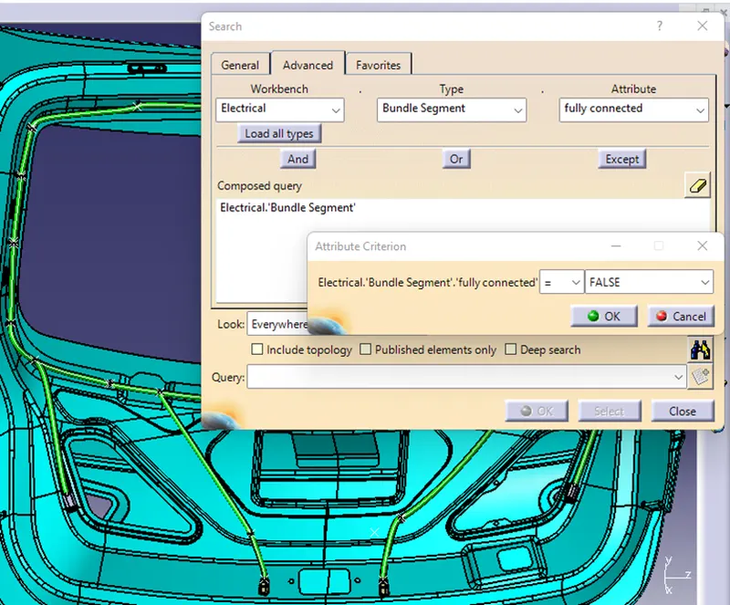
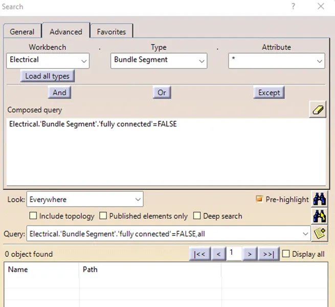
As can be illustrated, all the bundle segments are fully connected
Step 6: Apply Protective Coverings
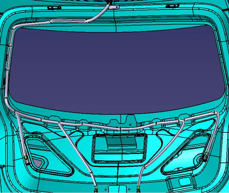
- To protect the bundles from high temperatures, add protective coverings to the wiring harness. The "define protection part" command in the "electrical part design" workbench creates a protective covering.
- By using the store device command and selecting the catalog file prepared for protective covering, the created corrugated tube can be added to the catalog. Then, the bundle segments are given the proper protective coatings keeping a 15mm distance from each connector.
Step 7: Wiring Harness Flattening
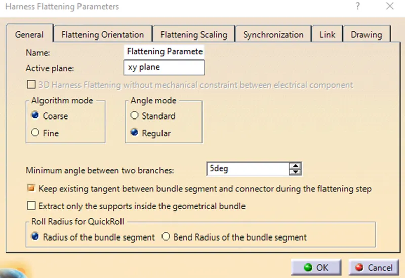
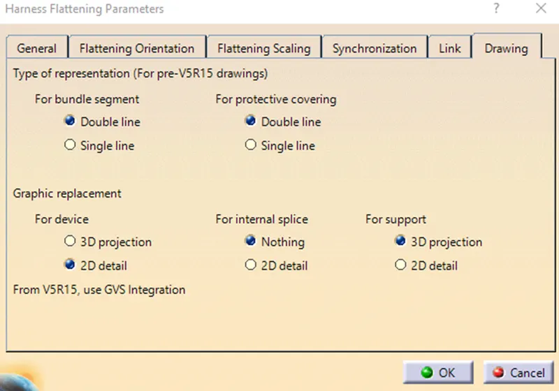
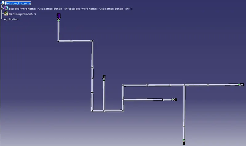
To flatten the wiring harness, create a new product file and save it with a representative name in the same folder as the backdoor context assembly. Then select Harness Flattening Parameters and define Harness Flattening Parameters on the “Electrical Harness Flattening” Workbench. 'Double line' for the bundle segment and 'Double' line for the protective covering must be selected before producing the flattened view.
Flattened View
Step 8: Drawing of the Flattened Wiring Harness
To generate a drawing of the harness, open a new drawing file, choose the command Select front view, then go to the flattened harness window and select an appropriate face. Right-click the drawing sheet and select properties. In the view tab, select "3D wireframe" and "is always visible" in the dress-up settings to make the bundle segments visible.