Project 2
BACK DOOR WIRING HARNESS
Aim: To design a geometrical bundle routing for the car back door.
What is Electric Harness?
Wire harness design is the process by which an engineer evaluates the requirements of an electrical part of system, given available physical space to create an assembly of wires to deliver power and information as needed.
For our wiring harness we had taken the reference of the Subaru Outback 05 for creating our harness routing for the back door.
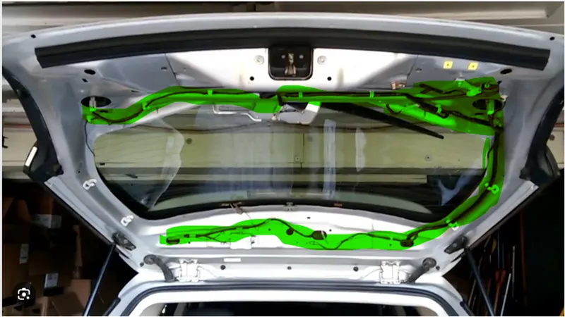
In this image we can see how the wiring is been routed around the back door and also what are the connection that are needed to be done at the back door of any normal car. The green color highlighted area is the harness of the back door. This includes the connection to the tail light, rear viper motor, antenna and No. plate light. We had route our Geometrical Bundle with this as a reference.
Wiring harness for the Back Door:
We were provided with the back door CAD file; on this CAD file we have to route our Geometrical Bundle.
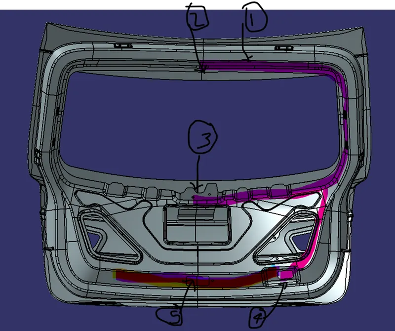
This is the CAD file we are provide with. As from the reference of our car we can see that wiring starts from the top of the door. So,
- ‘1’ is the entrance or the main supply port for the Geometrical Bundle
- ‘2’ is where the antenna is placed, so we have to route a small wire for the antenna from Main Supply
- ‘3’ is the Viper Motor placement, so we will split our main line and bring the connection to Viper Motor
- ‘4’ is the Tail Light connection, so we will bring the main bundle to the bottom and then split the main bundle in to three parts at the bottom to finish the electric harness
- ‘5’ is the No. Plate light, we had already split the main line for tail light and from that we will take one line for No. Plate
- The dark highlighted area is where the harness goes behind the internal panel.
Now, as we planned our Geometrical Bundle Routing its time to put the connector and necessary Clips in position for the Bundle Routing.
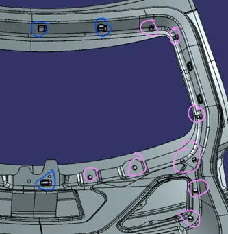
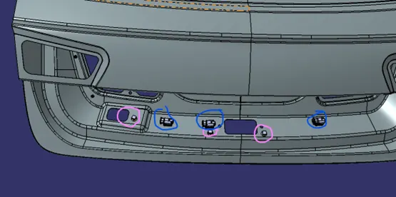
- Blue circles are the Connectors
- Pink circle are Clips
We have to route the wire on front and back of the inner panel, so we have placed the connectors and the clips in the position.
Note: Make sure the Clips are in proper orientation or else it will create the problem for bundle entry point.
For this Bundle Routing we had decided to use the following connector and clips for the better wire fitments.
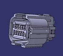
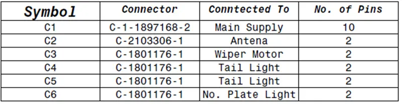
- C-1-1897168-2 (Main Entry Connector): This has 10 terminals for the all the wire routing.
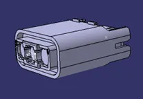
- C-2103306-1 (Antenna): This connector will provide the connection for the antenna. It only required the 2 terminals.
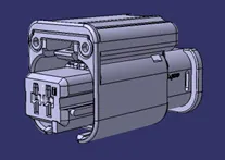
- C-1801176-1 (Viper Motor, Tail Light and No. Plate Light): This connector is used for the rest of the connection. This is also a 2-terminal connector.
All the connector are needed to the electrical defined. This will allow us to create the Bundle Routing.
We had also used the two different types of Clips for this harness routing.
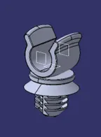
- C Mount Fir Tree (CAC702): This fir tree clip will hold the wire in position properly and it will not allow the wire to disturb the other components.
- Furr_Clip_20mm: This fir tree is commonly used for the electric harness.
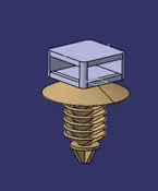
Just like the connector the clips are also needed to be electrically defined for routing the harness.
After all the components are the electrically defined and placed in required position, we can now the create the Geometrical Bundle.
Geometrical Bundle Routing
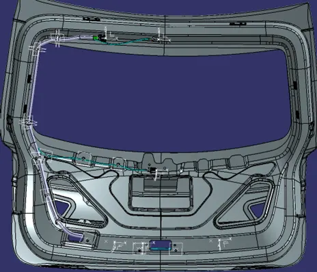
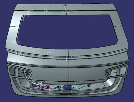
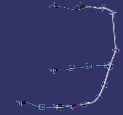
Note: Check the bundle continuity before flattening the Geometrical Bundle.
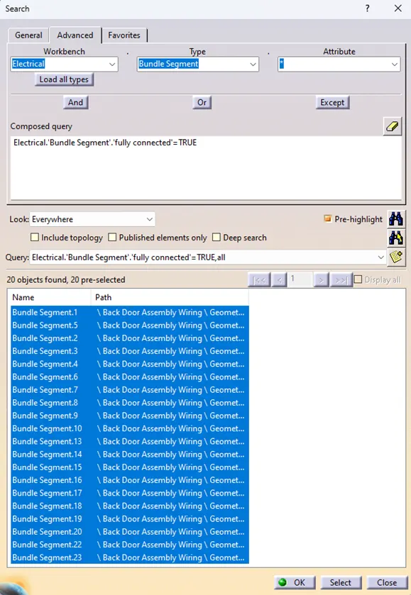
The Bundel continuity is checked. As, we can see that the all the bundle are connected. This step will confirm that the bundle is properly created and is fully connected. Sometimes the Geometrical Bundle is created but not full connected and it can cause a problem. So, always check for the Bundle continuity.
Geometrical Bundle Flattening
The Geometrical Bundle Flattening will give us a prospective of the geometrical bundle that is routed on the body in simpler form. One can read the drawing the and can understand the routing of the bundle. So, it is necessary to create the bundle flattening for the person to read the bundle.
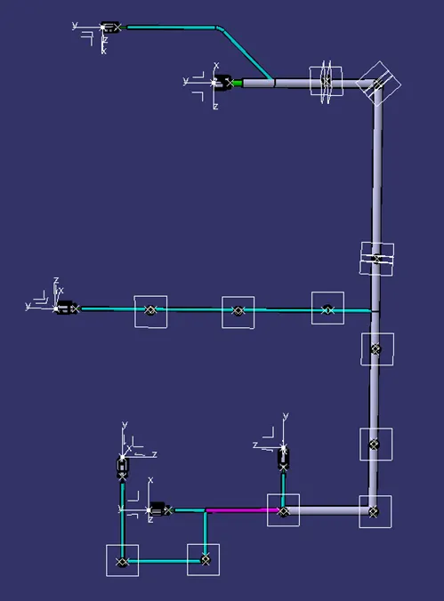
As, we can see how the bundle flattening simplifies the geometric bundle. This is flattening is then converted to drawing sheet so we can send it to Electric Harness Routing Engineer so he can route the harness.
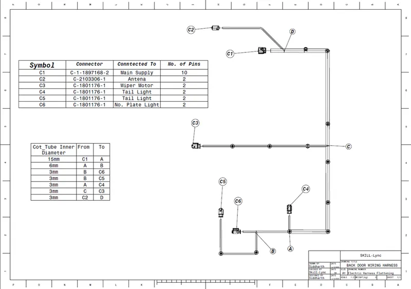
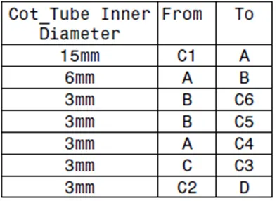
Just creating drawing is not enough so we have to give the details of the connector and clips that we used in the harness and also the protection covering that is used in the routing the harness because the Electric Harness Routing Engineer will not know about the types of connector and clips that are used in the routing.
Connectors Details
Cot_Tubes Details
Result: The Geometrical Bundle Routing of the car Back Door is completed and also all the required details is been added to finish the bundle routing.