Project 2
Project 2
For the same framing that was used in project 1, check if slab requires shear reinforcement or not. Also, check beam B1 for shear and see if stirrups is required. It is acceptable to use coefficients in IS 456-2000 for estimating shear force. If yes, provide stirrups as required.
Also, identify and design worst case column in the given plan using SP 16 (acceptable to generate interaction curve using spreadsheet). Finally, design the foundation for the same column assuming allowable bearing capacity of 100 kN/m2 at 2 m below ground level. Consider M30 concrete for column and M25 concrete for foundation.
Solution:
- Check of slab for shear
We can use coefficients in table 13 to determine shear force in slab. To determine if stirrups is required or not, let us consider the maximum shear force value based on the coefficients.
Per table 13, maximum shear force coefficient applicable is 0.6 for dead load as well as live load. This is applicable for location “At support Next to the End Support”.
Total factored uniform load on slab = 1.5*(6.25 + 3)=13.875 kN/m2
Maximum shear force =Vu=0.6* 13.875*L = 0.6*13.875*3=24.975 kN / m width
This shear force is acting within 1000 mm width of slab.
Vu/(b*d) = 24.975*1000/(1000*126)=0.198 MPa < τc,max (=3.1 MPa per table 20 for M25 concrete), OK.
Steel provided at top near support = 8 mm @200 mm
Number of rebars provided within 1000 mm width of slab = 6
Ast provided = 6*pi*82/4 = 301.6 mm2
Percentage steel provided = 100*Ast/(b*d) = 100*301.6/(1000*126) = 0.24%
Per table 19, τc for 0.24% steel and M25 concrete is 0.35 MPa
Concrete shear strength per meter width = τc*b*d = 0.35*1000*126 = 44100 N = 44.1 kN
Vu<Vc, therefore concrete is adequate, and no shear reinforcement is required in slab. Thickness of slab works as 150 mm.
- Design of beam for shear force
Dead load on beam = 22.25 kN/m
Live load on beam = 9 kN/m
Using table 13, the shear force coefficient to be used is 0.6
Maximum factored shear force in beam = Vu = 0.6*1.5*(22.25+9)*8 = 225 kN
Vu/(b*d) = 225*1000/(350*504)=1.28 MPa < τc,max, OK
Area of steel provided = 3*pi*322/4 = 2412.74 mm2
100*Ast/(b*d) = 100*2412.74/(350*504) = 1.368 %
Per table 19 of IS 456-2000, τc per 1.368% steel and M30 concrete = 0.73 MPa
Shear strength of concrete alone = Vc = τc*b*d = 0.73*350*504=128.8 kN
Vu > Vc, Stirrups is required
Stirrups need to be designed for force Vs = Vu – Vc = 225-128.8 = 96.2 kN
Let us assume 2 legged 8 mm stirrups
Asv = 2*pi*82/4 = 100.53 mm2
Let required spacing be s
Vs = 0.87*fy*Asv*d/sv
96.2*1000 = 0.87*415*100.53*504/sv
sv = 190.2 mm
Provide 175 mm stirrups spacing in the beam
Maximum spacing allowed = min(0.75*d, 300) = min (0.75*504, 300)= 300 mm
Minimum sear reinforcement:
Asv/(b*sv) >= 0.4/(0.87*fy)
100.53/(350*175) >= 0.4/(0.87*415)
1.64*10-3 > = 1.11*10-3
Therefore, the strirrups provided meets minimum shear reinforcement requirement
- Design of worst case column
The worst-case column is the one that is seeing maximum loading
Maximum loading will be seen by column with highest tributary area. This column is a typical edge column.
That column is the one indicated in the figure below:
Considering one of the 4 identified columns (each column will be subjected to equal load)
The column will see axial force from beams framing left to right and girder spanning North South.
Also, there will be moment acting in the column from the girder spanning North-South
The East-West beams are of size 350 mm x 550 mm. Let us assume the North-South girders are also of 350 mmx550 mm size.
Thickness of slab = 150 mm
Weight of slab = 25*0.15 = 3.75 kN/m2
Converting weight of beam as equivalent uniform load, we get
Equivalent uniform dead load of beam = 25*0.35*0.4/3 = 1.17 kN/m2
Weight of North South girder = 25*0.35*0.4=3.5 kN/m
Tributary width of girder = 8 m
Total uniform dead load on North-South girder = 3.5 + (3.75+1.17+2.5)*8 = 62.9 kN/m
Live load on girder = 3*8 = 24 kN/m
Factored uniform load on North South girder = 1.5*(62.9 + 24)=130.35 kN/m
Factored Load on column from this girder = 130.35*12/2 = 782.1 kN
Factored Moment in column from North South girder = 130.35*122/16 = 1173.2 kNm
Uniform dead load on East West beam supported by column = (3.75 + 2.5)*(3/2) + 1.17 = 10.5 kN/m
Live load on East West beam supported by column = 3*(3/2) = 4.5 kN/m
Axial load on column from East West beam due to dead load = 10.5*8 = 84 kN
Live load on column from East West beam due to live load = 4.5*8 = 36 kN
Factored compression on column from this beam = 1.5*(84+36)=180 kN
Total factored compression on column = 782.1 + 180 = 962.1 kN
Factored moment in column = 1173.2 kNm
Total service compression due to dead load on column = 62.9*6 + 84 = 461.4 kN
Total service compression due to live load on column = 24*6 + 36 = 180 kN
Service moment due to dead load = 62.9*122/16 = 566.1 kNm
Service moment in column due to live load = 24*122/16 = 216 kNm
Let us consider 500mm x 700mm column
Pu = 962.1 kN
Mu = 1173.2 kNm
B = 500 mm
D = 700 mm
The column is subjected to compression and uniaxial moment
Clear cover in column = 40 mm
Considering 8mm ties and 16mm longitudinal reinforcement, Effective cover to longitudinal reinforcement =d’= 40+8+16/2 = 56 mm
d’/D = 56/700=0.08
Using SP 16 and considering char per fy= 415 MPa, d’/D=0.1 and reinforcement distributed equally on four sides, we get
Mu/(fck*b*D2) = 1173.2*106/ (30*500*7002) = 0.16
Pu/(fck*b*D) = 962.1*1000/(30*500*700)=0.09
Based on the above parameters, p/fck = 0.12
P = 0.12*30 = 3.6
Total area of steel required = (3.6/100)*500*700 = 12600 mm2
Considering 32 mm diameter bars, total number of bars required = 12600/(pi*322/4) = 16
Provide 5 – 32 mm bars on each side so that total number of bars is 16
Minimum diameter of ties = max (6, Ф/4), where Ф is diameter of longitudinal reinforcement = max(6,32/4) = max(6,8) = 8 mm
Maximum allowable spacing of ties = min (Least dimension of column, 16*Ф, 300) = min(500,16*32,300)=min(500,512,300)= 300 mm
Provide 8mm ties@250 mm spacing
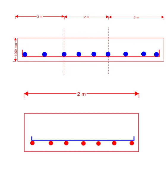
Since the center to spacing of rebar along width is 93 mm and along depth is 143 mm both of which are greater than 75 mm, each bar along edge needs to be ties in both directions. Therefore, additional links need to be provided as shown below
The above is the cross section of the column designed per the loads . 16-32 mm diameter bars and 8mm ties@250 mm spacing
- Design of foundation for this column.
Compression due to dead load from column = 461.4 kN
Compression due to live load from column = 180 kN
Moment due to dead load = 566.1 kNm
Moment due to live load = 216 kNm
Total service compression = P = 461.4+180 = 641.4 kN
Total service moment = M = 566.1 + 216 = 782.1 kNm
e = M/P = 782.1/641.4 = 1.22 m
For no net uplift, Length of the footing must be such that e < L/6
1.22 < L/6
L> 7.32 m
Let us consider 8 m long footing and 2m wide footing
Let us consider weight of backfill + weight of footing =ΔP= 15% of column load= 0.15*641.6 = 96.24 kN
Maximum bearing pressure under footing = (P+ΔP)/(B*L) + M*6/(B*L2) = (641.4+96.24)/(2*8) + (782.1*6)/(2*82) = 83 kN/m2 <100 kN/m2 , OK
Ultimate load on footing from column = Pu=1.5*641.4 = 962.1 kN
Ultimate moment on footing from column = Mu=1.5*782.1 = 1173.2 kNm
Ultimate net bearing pressure under footing = qu = Pu/(B*L) + Mu*6/(B*L2) = 961.2/(2*8) + 1173.2*6/(2/82) = 115 kN/m2
Let us conservatively assume that the bearing pressure under footing is uniform with magnitude of 115 kN/m2
Determination of Footing thickness :
One way shear force:
Critical section for one way shear check is at a distance ‘d’ away from face of column. Let effective depth be d meters
One way shear force = Vu = qu*2*(4-0.35-d) = 115*2*(4-0.35-d) = 839.5 – 230*d
Let us assume 0.25% steel in footing.
τc per table 19 for 0.25% steel and M25 concrete = 0.36 MPa
Shear strength of footing =Vc= 0.36*1000*2*d = 720*d
Vu = Vc
839.5-230*d = 720*d
d = 0.884 m = 884 mm
Two way shear strength:
Critical section for two way shear is at d/2 from face of column
Two way shear force demand = Vu = Pu – qu*(0.5+d)*(0.7+d) = 962.1-115*(0.5+0.884)*(0.7+0.884)=710 kN
Two way shear capacity = ks*0.25*sqrt(fck)*bo*d
Ks = 0.5 + 0.5/0.7 = 1.21
But ks cannot exceed 1. Therefore, ks = 1
bo = 2*(700+884 + 500+884)=5936 mm
d =884 mm
Two way shear capacity = 1*0.25*sqrt(25)*5936*884 = 6559280 N = 6559.28 kN
Two way shear demand is much less than two way shear capacity.
Therefore d = 884 mm is adequate for one way shear as well as two way shear
Let us consider 1000 thick footing.
Therefore, footing size is 2m x 8m x 1m
Pressure due to weight of footing = 25*1 = 25 kN/m2
Pressure due to weight of backfill = 18*(2-1)=18 kN/m2
Determination of flexural reinforcement:
Critical section for flexure is at face of column
Ultimate moment at face of column along long side = qu*B*(4-0.35)2/2 = 115*2*3.652/2 = 1532.1 kNm
Moment along short side at face of column = qu*L*(2-0.25)2/2 = 115*8*1.752/2 = 1408.75 kNm
Flexural reinforcement along long side:
Mu = 1532.1 kNm = 1532.1*106 Nmm
b = 2000 mm
fck = 25 MPa
fy = 415 MPa
Considering 50 mm cover and 20 mm rebar, effective depth along long side = dL = 1000-50-20/2 = 940 mm
Let percentage of steel required be p
Plugging all values as mentioned, we get
0.168*p2 -p + 0.24=0
p = 0.25%
Area of steel required = (0.25/100)*2000*940 = 4700 mm2 🡪 15 – 20mm bars
Spacing = (2000-50-50-20)/(15-1)=134 mm
Provide 125 mm spacing
Flexural reinforcement along short side:
Mu = 1408.75 kNm = 1408.75*106 Nmm
b = 7000 mm
fck = 25 MPa
fy = 415 MPa
Considering 50 mm cover and 20 mm rebar, effective depth along long side = dS = 1000-50—20-20/2 = 920 mm
Let percentage of steel required be p
Plugging all values as mentioned, we get
0.168*p2 -p + 0.066=0
p = 0.067%
Minimum percentage steel required = 0.12
Area of steel required = (0.12/100)*7000*920 = 7728 mm2 🡪 25 – 20mm bars
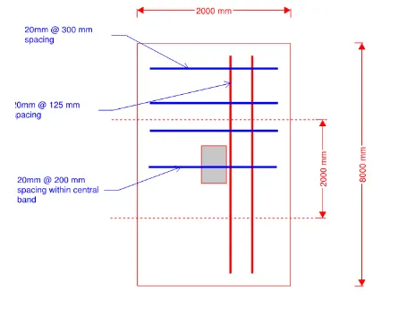
Area of steel required in central band of 2 m = Ast*2/(β+1) = 7728*2/[(8/2)+1] = 3091.2 mm2 🡪 10 – 20 mm bars
Spacing in central band = 2000/(10-1)=222.22 mm
Provide 200 mm spacing in central band
Number of bars outside central band = 25-10 = 15
Spacing required = [(8000-2000)-50-50-20]/(15-1)=420 mm
Maximum permissible spacing = 300 mm
Provide 300 mm spacing outside central band.
Therefore the reinforcement layout of footing is as shown below: