System-Level Simulation of an All-Terrain Vehicle
System-Level Simulation of an All-Terrain Vehicle
System-level simulation (SLS) is a collection of practical methods used in the field of systems engineering, in order to simulate, with a computer, the global behavior of large physical systems.
An all-terrain vehicle is an off-road vehicle which is capable of driving on and off paved or gravel surface.
A Model of BAJA ATV
The major Simulink blocks used to in-vehicle simulation model are:-
1. Driver Inputs - Throttle/brake profile
2. Engine - System-level model of spark-ignition or diesel engine
3. Transmission - continuously variable transmission (CVT)
4. Vehicle Body - Vehicle, tire, and brake
1. Driver Inputs
The input is taken from the driver in the form of throttle and brake.
1.1 Throttle
A throttle is a mechanism by which fluid flow is managed by constriction or obstruction. An engine's power can be increased or decreased by the restriction of inlet gases (by the use of a throttle), but usually decreased. The term throttle has come to refer, informally, to any mechanism by which the power or speed of an engine is regulated, such as a car's accelerator pedal.
Electronic Throttle Body
1.2 Brake
A brake is a mechanical device that inhibits motion by absorbing energy from a moving system. It is used for slowing or stopping a moving vehicle, wheel, axle, or to prevent its motion, most often accomplished by means of friction.
1.2.1 Double-Shoe Brake
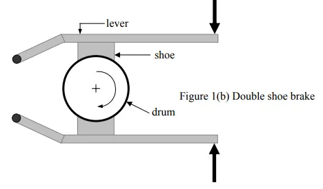
The Double-Shoe Brake block represents a frictional brake with two pivoted rigid shoes that press against a rotating drum to produce a braking action. The rigid shoes sit inside or outside the rotating drum in a diametrically opposed configuration. A positive actuating force causes rigid shoes to press against the rotating drum. Viscous and contact friction between the drum and the rigid shoe surfaces cause the rotating drum to decelerate.
2 Engine
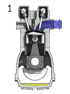
An engine is a machine designed to convert one form of energy into mechanical energy.
4-Stroke Petrol Engine
2.1 Generic Engine
Internal combustion engine with throttle and rotational inertia and time lag. Engine types include spark-ignition and diesel. Speed-power and speed-torque parameterizations are provided. A throttle physical signal input specifies the normalized engine torque. Optional dynamic parameters include crankshaft inertia and response time lag. A physical signal port outputs engine fuel consumption rate based on the choice of fuel consumption model.
3. Transmission
A transmission is a machine in a power transmission system, which provides controlled application of the power. Often the term 5-speed transmission refers simply to the gearbox that uses gears and gear trains to provide speed and torque conversions from a rotating power source to another device.
3.1 Continuously Variable Transmission (CVT)
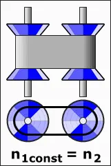
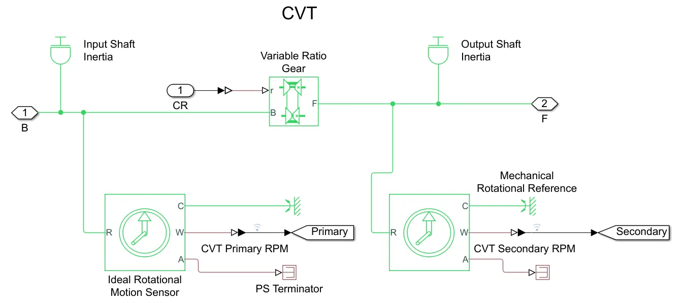
A continuously variable transmission (CVT) is an automatic transmission that can change seamlessly through a continuous range of gear ratios. This contrasts with other transmissions that provide a limited number of gear ratios in fixed steps. The flexibility of a CVT with suitable control may allow the engine to operate at a constant RPM while the vehicle moves at varying speeds.
3.1.1 Variable Transmission Ratio
Dynamic gearbox with variable and controllable gear ratio, transmission compliance, and friction losses. The Variable Ratio Transmission block represents a gearbox that dynamically transfers motion and torque between the two connected driveshaft axes, base and follower. Ignoring the dynamics of transmission compliance, the driveshafts are constrained to corotate with a variable gear ratio that you control.
4. Vehicle Body
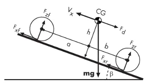
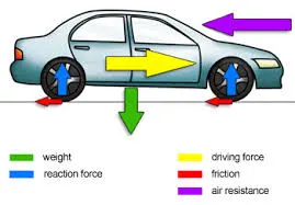
The Vehicle Body block represents a two-axle vehicle body in longitudinal motion. The vehicle can have the same or a different number of wheels on each axle. For example, two wheels on the front axle and one wheel on the rear axle. The vehicle wheels are assumed identical in size. The vehicle can also have a center of gravity (CG) that is at or below the plane of travel.
The block accounts for body mass, aerodynamic drag, road incline, and weight distribution between axles due to acceleration and road profile.
Vehicle Dynamics and Motion
where
`g` is acceleration due to gravity
`beta` is road inclination angle
`m` is mass of the vehicle
`h` is the height center of gravity (CG) above the ground
`a,b` are the distance of front and rear axles, respectively, from the normal projection point of vehicle CG onto the common axle plane
`V_x` is the velocity of vehicle
`F_(xf), F_(xr)` are the longitudinal forces on front and rear wheel respectively
`F_(Nf), F_(Nr)` are the Normal load forces on front and rear wheel respectively
Tire (Magic Formula)
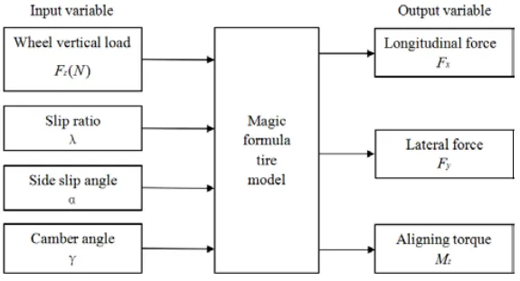
A tire with longitudinal behavior given by Magic Formula coefficients. An empirical equation based on four fitting coefficients. The block can model tire dynamics under constant or variable pavement conditions.
The general form of the Magic Formula,
`y=D*sin{C*arctan[Bx-E*(arctan(Bx))]}`
where B, C, D, and E or stiffness, shape, peak, and curvature represent fitting constants which are four dimensionless coefficients and y is a force or moment resulting from a slip parameter x.
Other Common Blocks Used
1. Inertia
The Inertia block represents an ideal mechanical rotational translational inertia. The ideal inertia torque is given by the relation
`T=J(dw)/dt`
`T` is the inertia torque
`J` is inertia
`w` is angular velocity
`t` is time
2. Gain
The Gain block multiplies the input by a constant value (gain). The input and the gain can each be a scalar, vector, or matrix. You specify the value of gain in the Gain parameter. The Multiplication parameter lets you specify element-wise or matrix multiplication. For matrix multiplication, this parameter also lets you indicate the order of the multiplicands.
3. PS Terminator
Use the PS Terminator block to cap physical signal output ports that do not connect to other blocks. Unconnected physical signal output ports do not generate warnings. However, you can use a PS Terminator block for clarity, to indicate that the signal was not inadvertently left unconnected.
4. PS Signal Constant
The PS Constant block generates a physical signal of a constant value. You specify the value and unit of the signal as the Constant parameter.
6. PS- Simulink Converter
Convert physical signal into the Simulink output signal. Use this block to connect outputs of a Physical Network diagram to Simulink scopes or other Simulink blocks.
7. Simulink-PS Converter
Convert a Simulink input signal into a physical signal. Use this block to connect Simulink sources or other Simulink blocks to the inputs of a Physical Network diagram.
8. Rotational Free End
The Rotational Free End block represents a mechanical rotational port that rotates freely, without torque. You can use this block to terminate mechanical rotational ports on other blocks that you want to leave unconnected.
9. Variable Transmission Ratio
Dynamic gearbox with variable and controllable gear ratio, transmission compliance, and friction losses. The Variable Ratio Transmission block represents a gearbox that dynamically transfers motion and torque between the two connected driveshaft axes, base and follower. Ignoring the dynamics of transmission compliance, the driveshafts are constrained to corotate with a variable gear ratio that you control.
10. Ideal Rotational Motion Sensor
Ideal Mechanical Rotational Motion Sensor is a device that converts an across variable measured between two mechanical rotational nodes into a control signal proportional to angular velocity or angle. You can specify the initial angular position (offset) as a block parameter.
11. PS Terminator
Use the PS Terminator block to cap physical signal output ports that do not connect to other blocks. Unconnected physical signal output ports do not generate warnings. However, you can use a PS Terminator block for clarity, to indicate that the signal was not inadvertently left unconnected.
12. Simple Gear
Simple gear of base and follower wheels with adjustable gear ratio, friction losses, and triggered faults. The Simple Gear block represents a gearbox that constrains the connected driveline axes of the base gear, B, and the follower gear, F, to corotate with a fixed ratio that you specify.
13. Mechanical Rotational Reference
Reference connection for mechanical rotational ports. It represents a reference point, or frame, for all mechanical rotational ports. All rotational ports that are rigidly clamped to the frame (ground) must be connected to a Mechanical Rotational Reference block.
14. Ideal Rotational Motion Sensor
Ideal Mechanical Rotational Motion Sensor is a device that converts an across variable measured between two mechanical rotational nodes into a control signal proportional to angular velocity or angle. You can specify the initial angular position (offset) as a block parameter.
15. PS Terminator
Use the PS Terminator block to cap physical signal output ports that do not connect to other blocks. Unconnected physical signal output ports do not generate warnings. However, you can use a PS Terminator block for clarity, to indicate that the signal was not inadvertently left unconnected.
16. Scope
Display signals generated during simulation. The Scope is optimized for general time-domain simulation.
17. From
The From block accepts a signal from a corresponding Goto block, then passes it as output. The data type of the output is the same as that of the input from the Goto block. From and Goto blocks allow you to pass a signal from one block to another without actually connecting them.
18. Goto
The Goto block passes its input to its corresponding From blocks. The input can be a real- or complex-valued signal or vector of any data type. From and Goto blocks allow you to pass a signal from one block to another without actually connecting them.
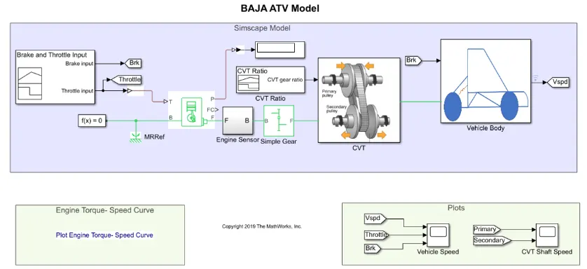
BAJA ATV model with Continuously Variable Transmission(CVT)
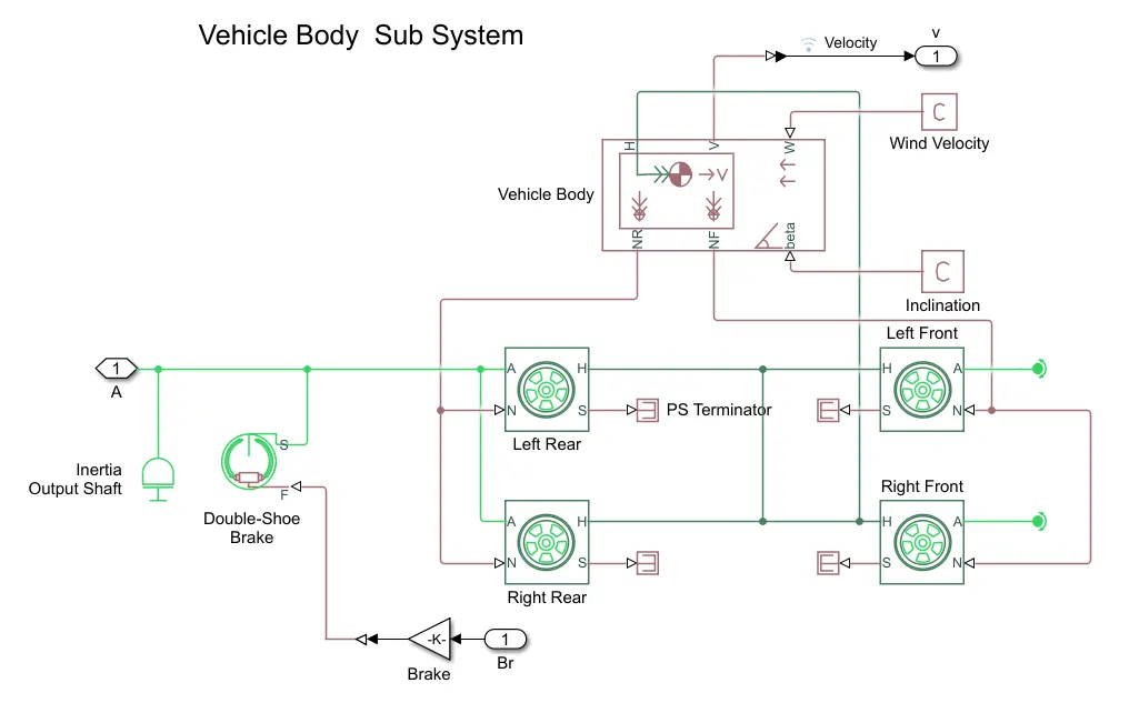
Vehicle Body Sub System
CVT Sub System
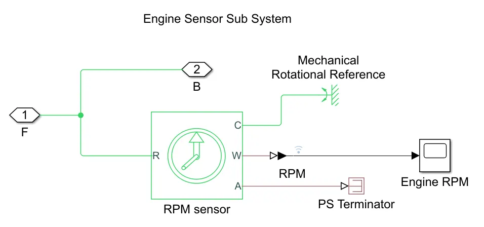
Engine Sensor Sub System
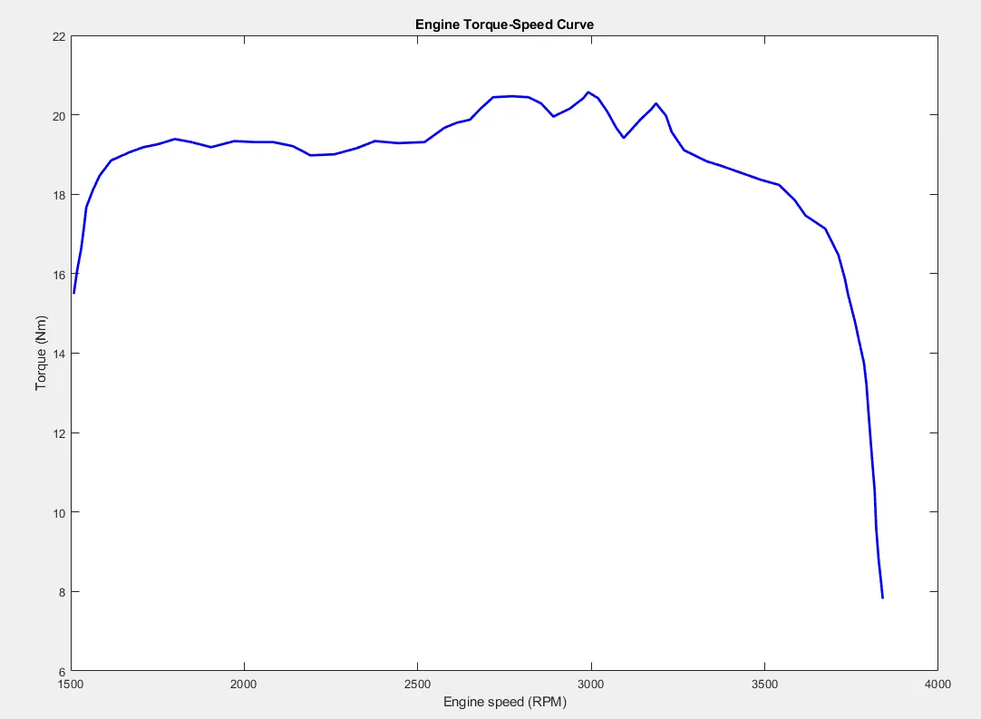
Torque vs RPM for the Engine
From the plot, it is absorbed that the maximum torque generated by the engine is at 2.9911e+03 rpm and the max torque is 20.5703
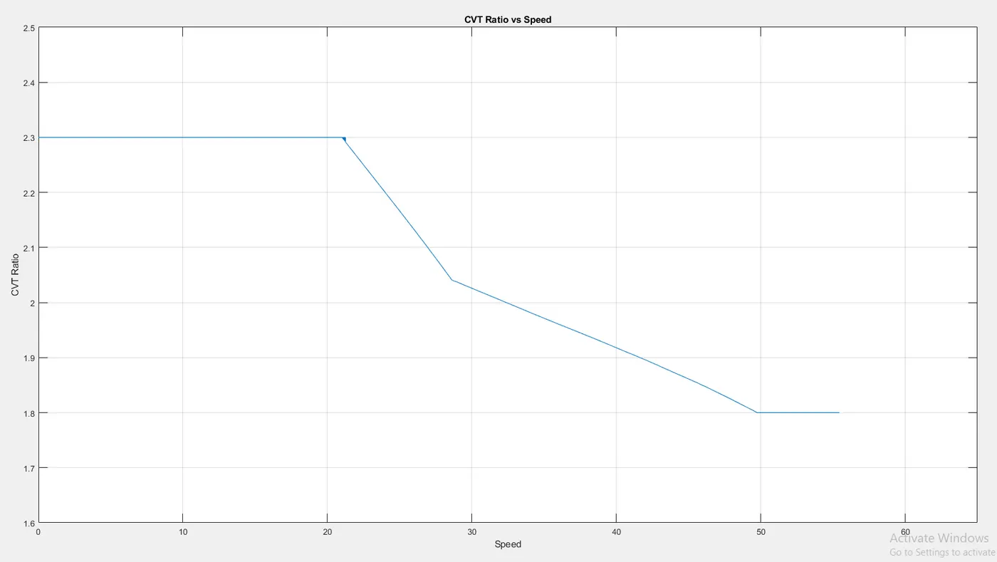
Lookup Table Visualisation
From the below graph it is visible that the Speed increases with the decrease in CVT Ratio. At the initial stage, the vehicle requires higher torque in order to overcome the force acting on it. But as the vehicle moves and the gear ratio decreases the speed of the vehicle starts to increase with an increase in the throttle. If the throttle is not given with the decrease in the gear ratio the vehicle speed will decrease and as the power is required to produce the torque at a lower gear ratio is high.
Running the Model
Case 1: Running the model with default signals
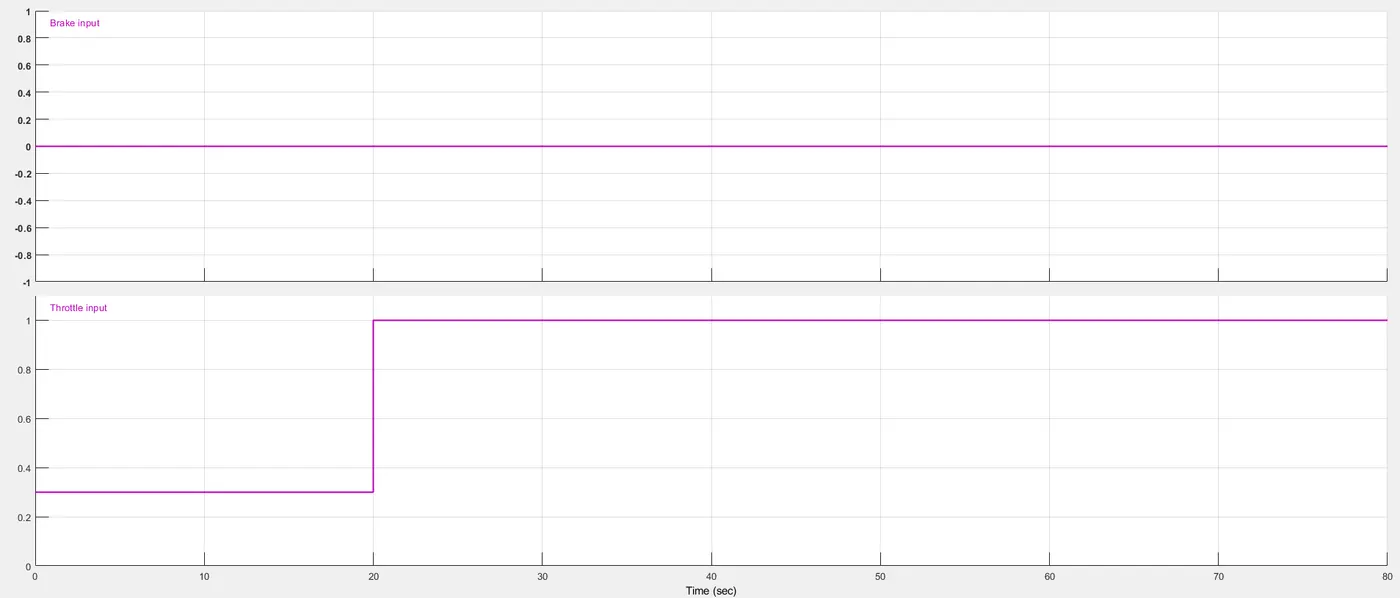
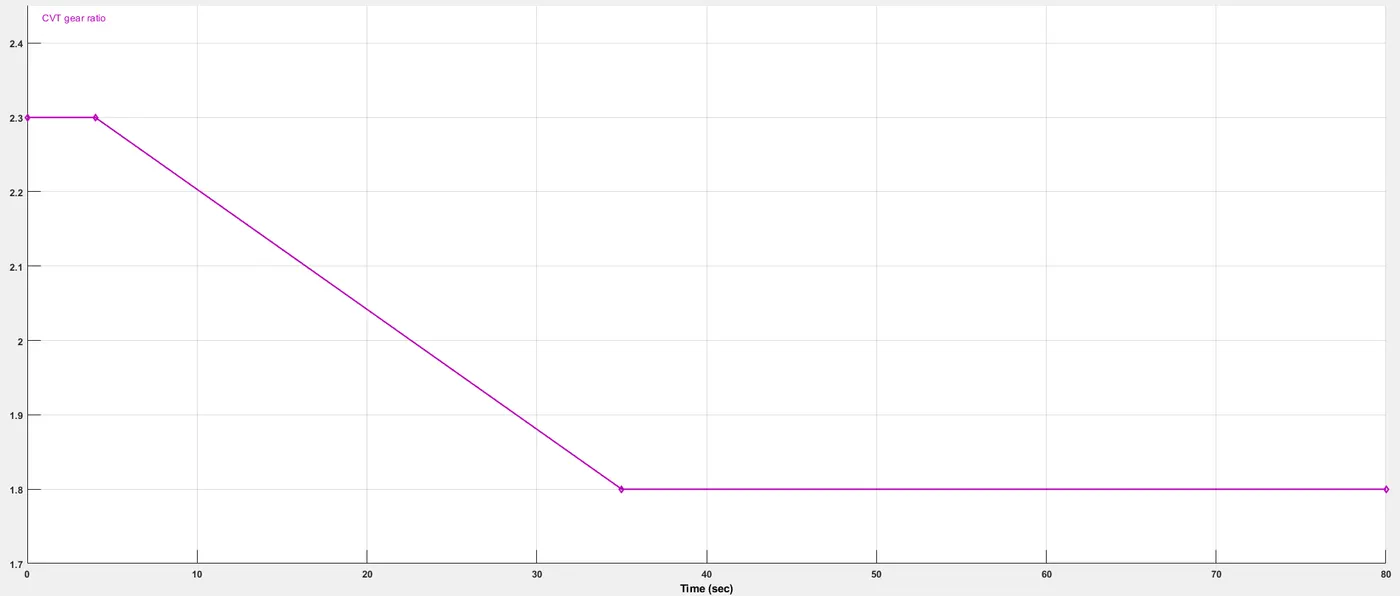
The vehicle when starts to move the CVT gear ratio is 2.3 which gives higher torque, which is kept constant for 3-5 seconds and enables the rapid acceleration which is seen as speed increases with the constant throttle. The Brake input is kept at zero throughout the simulation.
Throttle and Brake Default Signal
CVT Ratio Default Signal
Results from the Scope
Speed vs Throttle and Brake
The vehicle is accelerated rapidly as it goes from 0 to 20+ in milliseconds at the initial and then the rate of acceleration decreases as the throttle is kept constant and the CVT gear ratio is decreased. At time=20 the throttle is increased and the speed starts to increase at steady acceleration up till a point where the speed becomes constant . 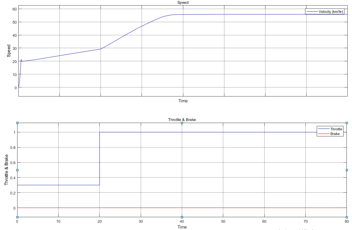
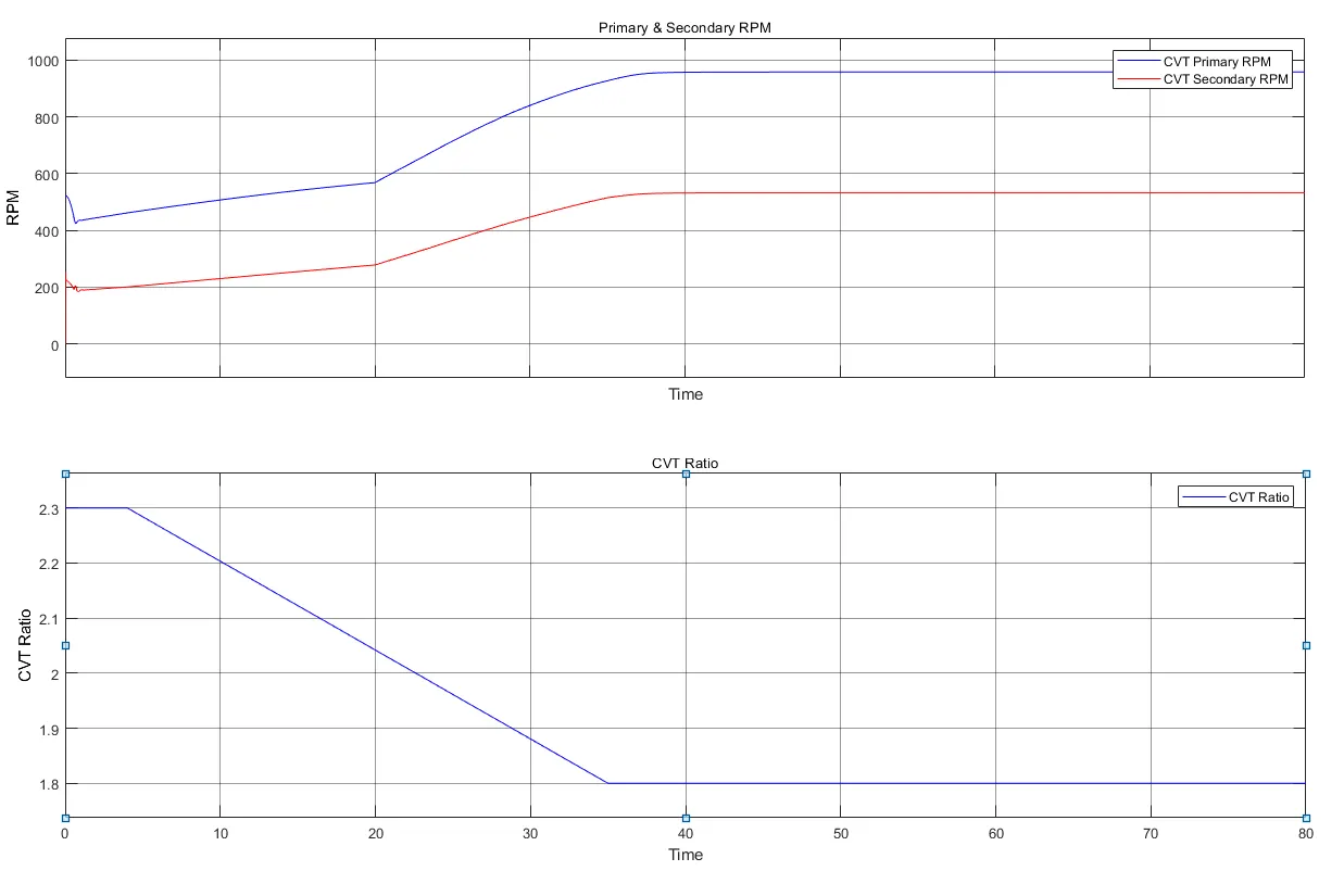
CVT Ratio Vs RPM of Primary and Secondary Shaft
In CVT the primary shaft is connected to the engine via a simple gear. The primary shaft shows a similar curve to the engine RPM and as the secondary shaft is connected to the wheels it shows characteristics similar to the vehicle speed as per the physical conditions.
As the engine is started we can see that the primary shaft starts from around 500 rpm and the secondary shaft starts from zero.
Engine RPM vs Time
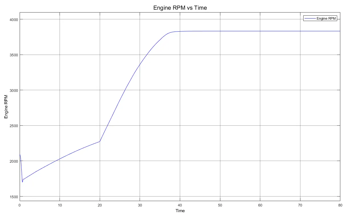
Case 2: Applying steady acceleration and brakes once the steady speed is achieved
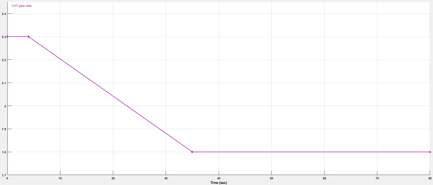
The Throttle is given with a uniform slope, starting at 0.3 and goes up till 1 in 20 seconds. The brake is gradually applied when the constant speed is achieved and the magnitude of the brake is increased to 1 and then the throttle is applied. The CVT ratio remains the same as per the initial condition.
Input Signal for steady acceleration and brakes once the steady speed is achieved
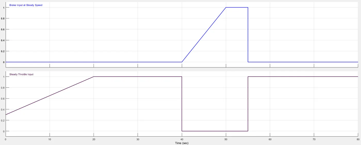
CVT Ratio
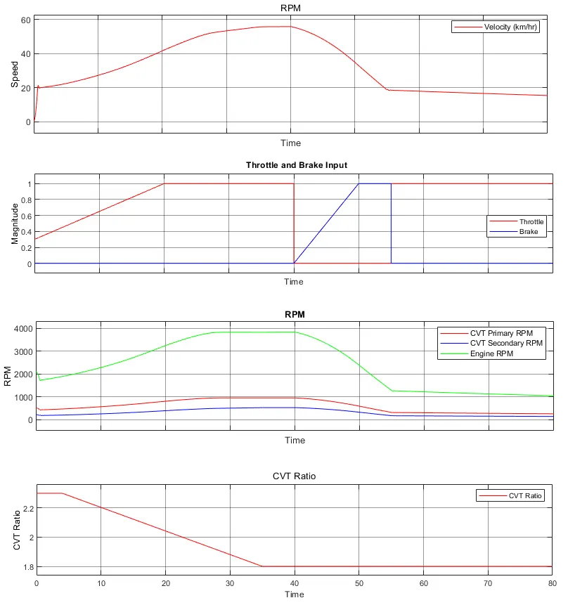
Results from the Scope
The results from the speed show that the vehicle accelerated from 0 to 20 in less than 4 seconds at CVT ratio of 2.3, but as the gear ratio starts to decrease the torque decreases, and the load on the engine increases, and the speed increases at a slow rate.
When the vehicle reaches a steady speed of about 55 the brakes are gradually applied and the throttle is removed for the applied brake. The vehicle speed and engine rpm decrease. The speed falls to below 20.
The brakes are removed and the throttle is applied with a magnitude of 1 but still, the vehicle does not accelerate, and the speed keeps decreasing due to the load increased by the smaller CVT Ratio.
Case 3: Throttle and Brake signal remains the same as case 2 and the CVT Ratio is varied at the application of brake
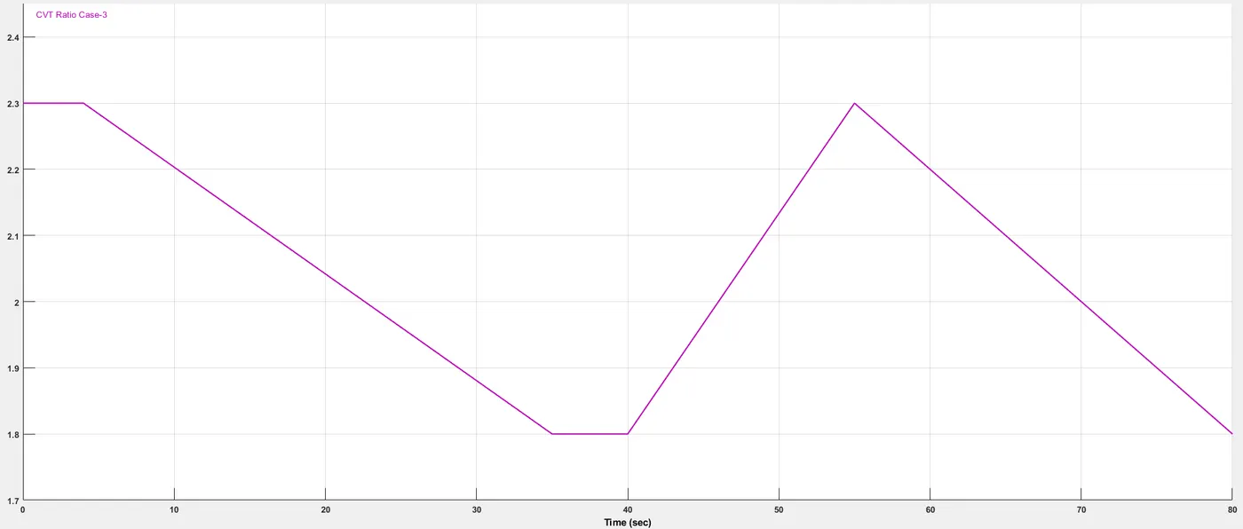
The Throttle is given with a uniform slope, starting at 0.3 and goes up till 1 in 20 seconds. The brake is gradually applied when the constant speed is achieved and the magnitude of the brake is increased to 1 and then the throttle is applied. The CVT ratio is changed with the application of brake to match the torque required at the lower speed. The CVT ratio is brought to the value of 2.3 and then gradually decreased to increase the speed of the vehicle.
Input Signals
Throttle and Brake
CVT Ratio
Initially, the CVT ratio is kept the same but after the application of brake, the CVT ratio is decreased in order to provide higher torque as per reduced speed of the vehicle.
Results from the Scope
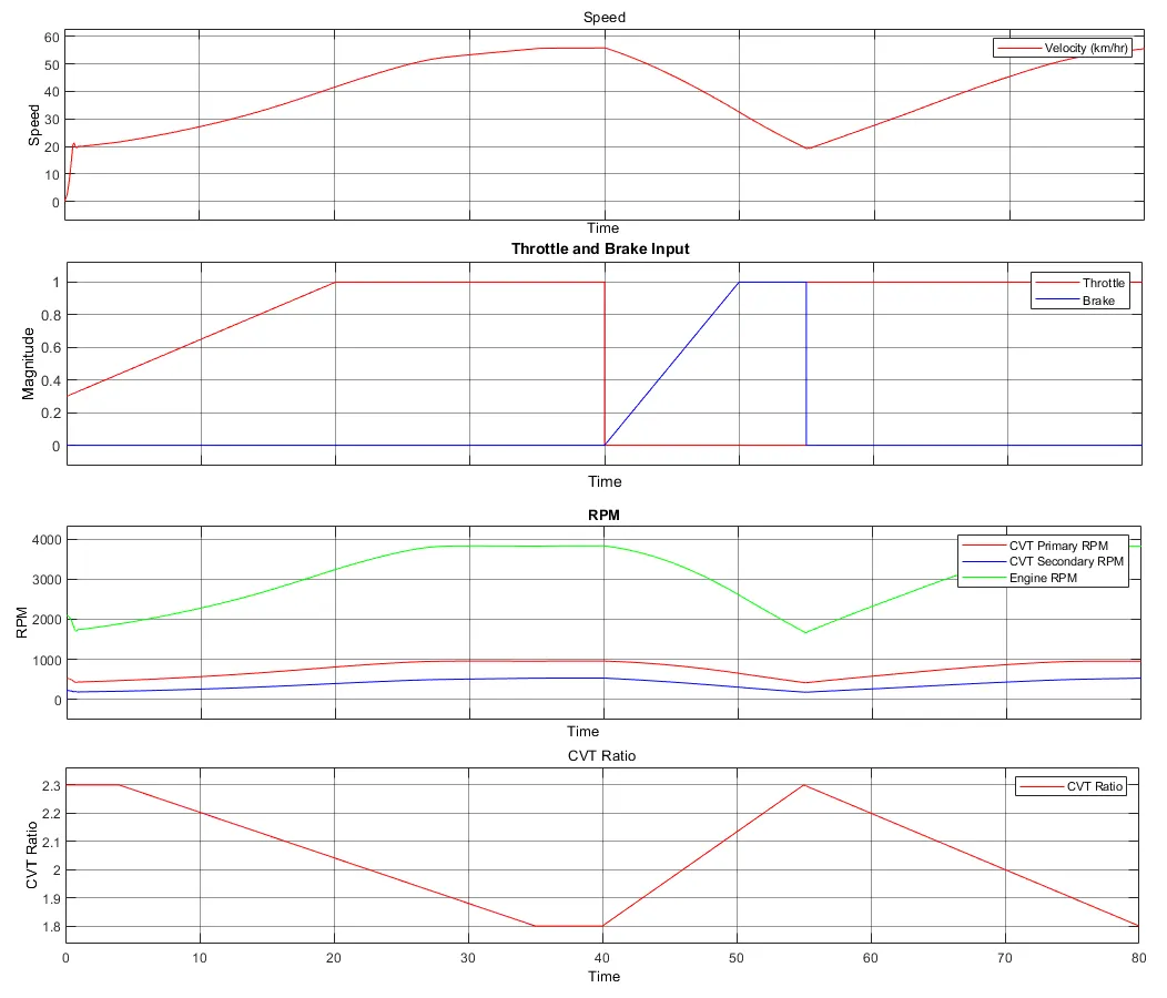
The results from the speed show that the vehicle accelerated from 0 to 20 in less than 4 seconds at CVT ratio of 2.3, but as the gear ratio starts to decrease the torque decreases, and the load on the engine increases, and the speed increases at a slow rate.
When the vehicle reaches a steady speed of about 55 the brakes are gradually applied and the throttle is removed for the applied brake. The vehicle speed and engine rpm decrease. The speed falls to below 20.
The brakes are removed and the throttle is applied with a magnitude of 1 and the CVT ratio is increased thus increasing the torque and reducing the load on the engine. The CVT ratio is gradually decreased, the vehicle speed also increases the reduction in CVTratio.
Conclusion
In real-world application is very important to understand the relation between the engine speed (rpm), the gear ratio, and torque. The acceleration and speed requirements can be met by varying the throttle(engine power) and the gear ratio.
For example in case 2 when the vehicle speed was decreased due to the application of brake we applied full throttle in order to accelerate but due to the less torque at lower gear ratio the acceleration was not achieved, while in case 3 the gear ratio was increased with the decrease in speed to meet the torque requirement and we saw that the vehicle was able to accelerate.