Project 1- Traffic Jam Assistant Feature
Project Title: Development of Traffic Jam Assistant Feature for Advanced Driver Assistance System (ADAS)
1. Introduction
The Traffic Jam Assistant is an essential feature in modern Advanced Driver Assistance Systems (ADAS). It is designed to assist drivers during dense traffic conditions and traffic jams by partially automating vehicle control. The system takes over longitudinal and lateral guidance of the vehicle, allowing it to drive off, accelerate, brake, and steer within the lane under certain constraints. This feature significantly reduces driver stress in heavy traffic and helps to avoid rear-end collisions.
2. Objective
The objective of this project is to develop and implement a specific requirement of the Traffic Jam Assistant algorithm using Model-Based Development (MBD) in MATLAB Simulink. The implementation focuses on the Instrument Panel Cluster (IPC) aspect of the system, which provides necessary information to the driver.
3. Basic Working Principle
The Traffic Jam Assistant is built on the foundation of Adaptive Cruise Control (ACC) with stop & go functionality, combined with Lane Keeping Support (LKS). When activated, the system continuously monitors the speed of surrounding vehicles and adjusts the vehicle's speed accordingly. If traffic is detected to be moving at speeds less than 60 kmph, the driver can activate the Traffic Jam Assistant, allowing the vehicle to automatically follow the car in front, handling acceleration, braking, and steering within the same lane.
4. Problem Statement
The project focuses on developing a specific requirement of the Traffic Jam Assistant algorithm, particularly the logic involved in the Instrument Panel Cluster (IPC) display. The project is a subset of the overall Traffic Jam Assistant algorithm, designed to familiarize developers with Model-Based Development (MBD) in MATLAB.
5. Methodology
The following steps and processes were followed to develop the model:
- Model Development in MATLAB Simulink: The model was created following MBD guidelines.
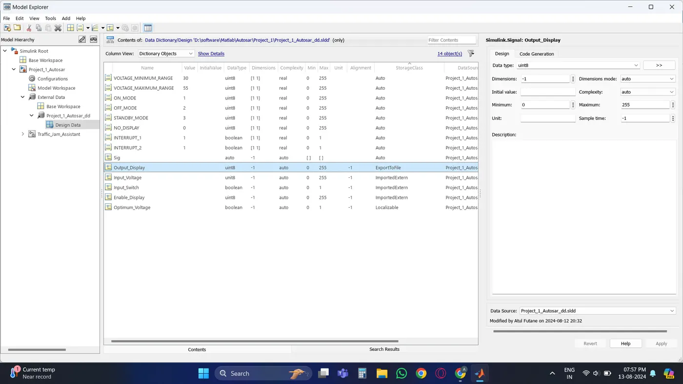
- Simulink Data Dictionary: A Simulink Data Dictionary was created and linked to the model for efficient data management.
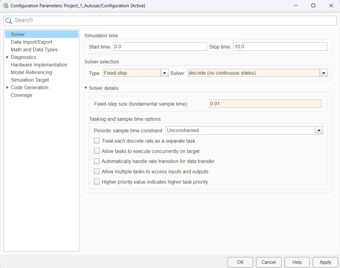
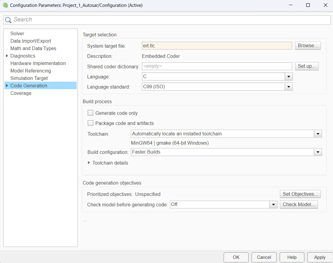
- Model Setting: The model was set up for code generation using Embedded Coder.
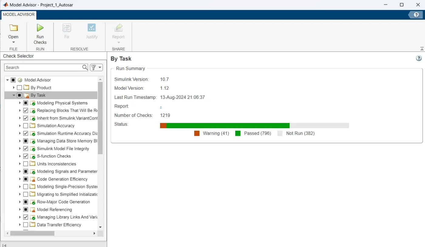
- Model Advisor Report: A Model Advisor Report was generated to ensure compliance with modeling standards.
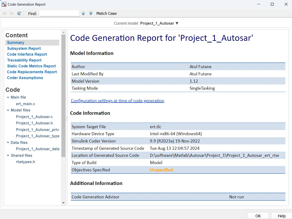
- Code Generation: The final step involved generating code from the Simulink model using Embedded Coder.
6. Input and Output Signals
Input Signals:
| Name | Data Type | Range |
|---|---|---|
| Input_Voltage | uint8 | 0 - 255 |
| Input_Switch | boolean | 0 - 1 |
| Enable_Display | uint8 | 0 - 255 |
Output Signal:
| Name | Data Type | Range |
|---|---|---|
| Output_Display | uint8 | 0 - 255 |
Calibration Signals:
| Name | Data Type | Range | Initial Value |
|---|---|---|---|
| VOLTAGE_MINIMUM_RANGE | uint8 | 0 - 255 | 30 |
| VOLTAGE_MAXIMUM_RANGE | uint8 | 0 - 255 | 50 |
| OFF_MODE | uint8 | 0 - 255 | 2 |
| ON_MODE | uint8 | 0 - 255 | 1 |
| STANDBY_MODE | uint8 | 0 - 255 | 3 |
| INTERRUPT_1 | boolean | 0 - 1 | 1 |
| INTERRUPT_2 | boolean | 0 - 1 | 1 |
| NO_DISPLAY | uint8 | 0 - 255 | 0 |
Local Signal:
| Name | Data Type | Range |
|---|---|---|
| Optimum_Voltage | boolean | 0 - 1 |
7. Requirements
Requirement No 1: Voltage Comparison
- The input signal Input_Voltage is compared against the calibration signals VOLTAGE_MINIMUM_RANGE and VOLTAGE_MAXIMUM_RANGE.
- The input signal Input_Voltage must be within the range defined by these calibration signals.
- The output signal Optimum_Voltage indicates whether the Input_Voltage is within the desired range and serves as an input to the DisplayUnit subsystem.
Requirement No 2: DisplayUnit Subsystem
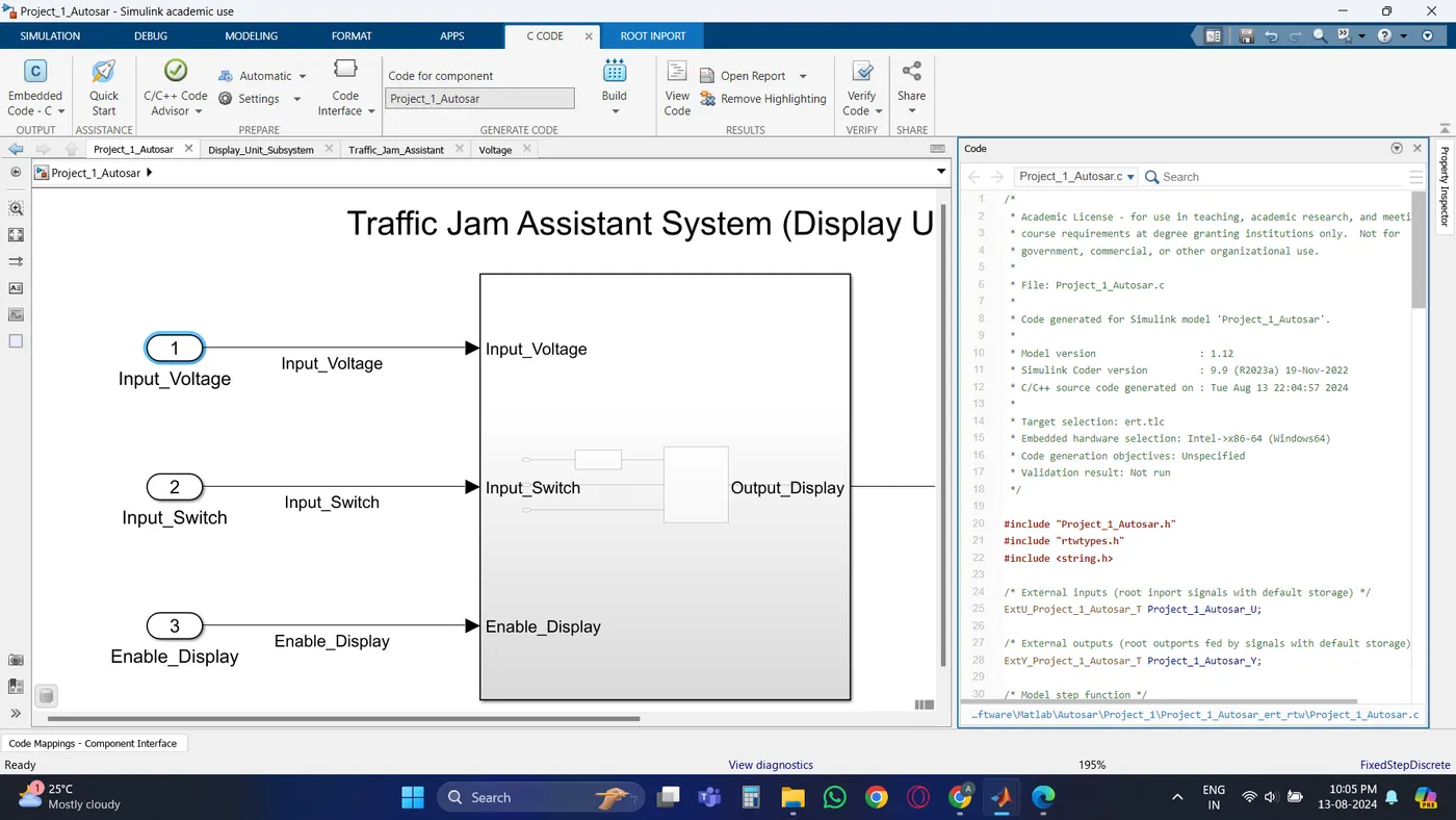
- The DisplayUnit subsystem receives the input signals Optimum_Voltage, Input_Switch, and Enable_Display.
- The signal Enable_Display is saturated within the range of 0 to 7.
- A multiport switch compares Enable_Display against predefined values, and its inputs are connected to the calibration signals ON_MODE, OFF_MODE, and STANDBY_MODE.
- The output of the multiport switch is fed into the first input of a Switch block, with the third input connected to NO_DISPLAY.
- An AND gate compares the NOT value of Input_Switch with Optimum_Voltage and the equality of INTERRUPT_1 and INTERRUPT_2. The result is fed into the second input of the Switch block.
- The final output from the Switch block is the Output_Display signal.
8. Implementation
The implementation followed the Model-Based Development approach, starting with the creation of the model in MATLAB Simulink. The model was then configured for code generation using Embedded Coder, and a Simulink Data Dictionary was used for data management. A Model Advisor Report was generated to ensure compliance with best practices, and the final step involved generating the code.
9. Model
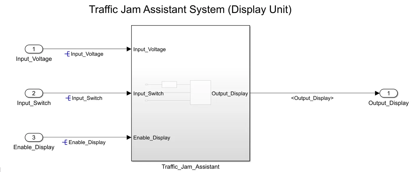
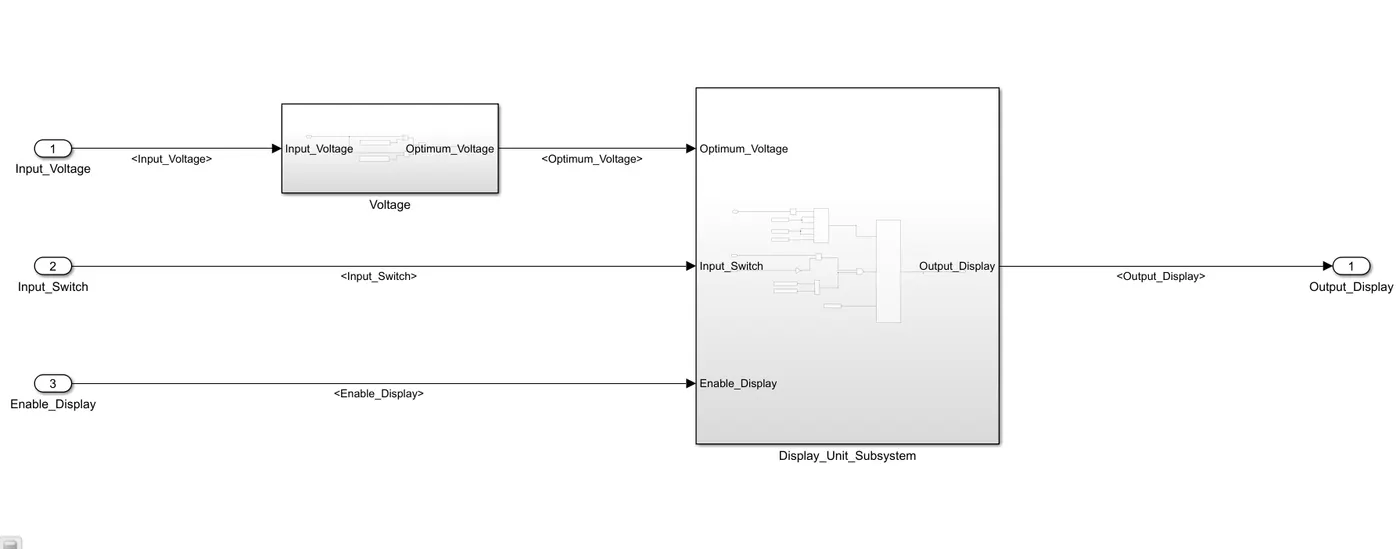
Subsystem1:
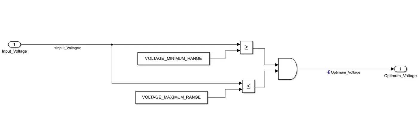
Subsystem2:
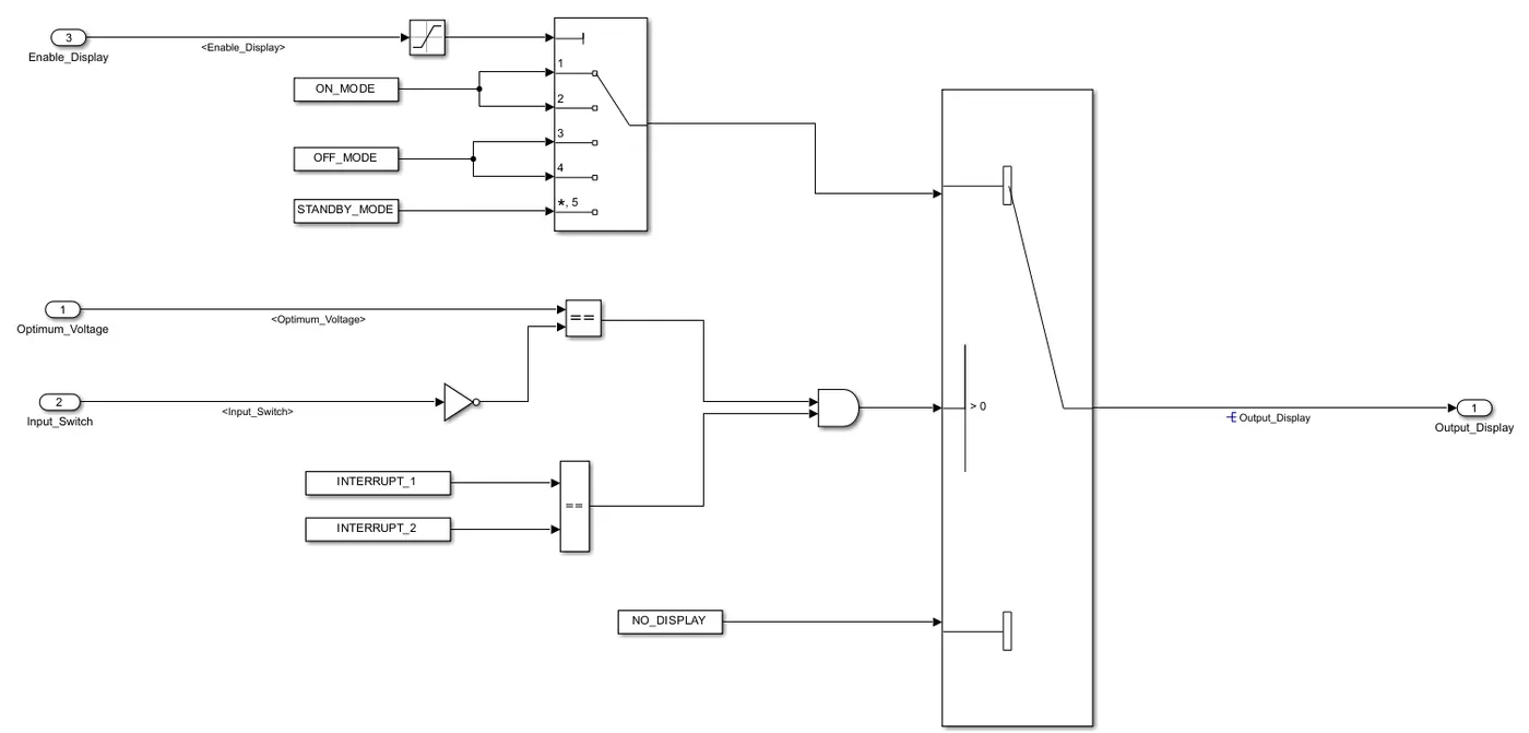
10. SLDD:
11. Model Setting:
12. Model Advisor Report:
13. Code Generation Report:
14. Generated Code
/*
* Academic License - for use in teaching, academic research, and meeting
* course requirements at degree granting institutions only. Not for
* government, commercial, or other organizational use.
*
* File: Project_1_Autosar.c
*
* Code generated for Simulink model 'Project_1_Autosar'.
*
* Model version : 1.12
* Simulink Coder version : 9.9 (R2023a) 19-Nov-2022
* C/C++ source code generated on : Tue Aug 13 22:04:57 2024
*
* Target selection: ert.tlc
* Embedded hardware selection: Intel->x86-64 (Windows64)
* Code generation objectives: Unspecified
* Validation result: Not run
*/
#include "Project_1_Autosar.h"
#include "rtwtypes.h"
#include <string.h>
/* External inputs (root inport signals with default storage) */
ExtU_Project_1_Autosar_T Project_1_Autosar_U;
/* External outputs (root outports fed by signals with default storage) */
ExtY_Project_1_Autosar_T Project_1_Autosar_Y;
/* Model step function */
void Project_1_Autosar_step(void)
{
real_T tmp;
/* Switch: '<S2>/Switch' incorporates:
* Constant: '<S3>/Constant'
* Constant: '<S3>/Constant1'
* Inport: '<Root>/Input_Switch'
* Inport: '<Root>/Input_Voltage'
* Logic: '<S2>/AND'
* Logic: '<S3>/AND'
* RelationalOperator: '<S2>/Equal'
* RelationalOperator: '<S3>/GreaterThan'
* RelationalOperator: '<S3>/GreaterThan1'
*/
if (((((Project_1_Autosar_U.Input_Voltage >= ((uint8_T)30U)) &&
(Project_1_Autosar_U.Input_Voltage <= ((uint8_T)55U))) ? ((int32_T)1) :
((int32_T)0)) != ((int32_T)(Project_1_Autosar_U.Input_Switch ? 1 : 0))) &&
(Project_1_Autosar_ConstB.Equal1)) {
/* Saturate: '<S2>/Saturation' incorporates:
* Inport: '<Root>/Enable_Display'
*/
if (Project_1_Autosar_U.Enable_Display > 7.0) {
tmp = 7.0;
} else if (Project_1_Autosar_U.Enable_Display < 0.0) {
tmp = 0.0;
} else {
tmp = Project_1_Autosar_U.Enable_Display;
}
/* MultiPortSwitch: '<S2>/Multiport Switch' incorporates:
* Saturate: '<S2>/Saturation'
*/
switch ((int32_T)tmp) {
case 0:
/* Outport: '<Root>/Output_Display' incorporates:
* Constant: '<S2>/Constant'
*/
Project_1_Autosar_Y.Output_Display = ((uint8_T)1U);
break;
case 1:
/* Outport: '<Root>/Output_Display' incorporates:
* Constant: '<S2>/Constant'
*/
Project_1_Autosar_Y.Output_Display = ((uint8_T)1U);
break;
case 2:
/* Outport: '<Root>/Output_Display' incorporates:
* Constant: '<S2>/Constant1'
*/
Project_1_Autosar_Y.Output_Display = ((uint8_T)2U);
break;
case 3:
/* Outport: '<Root>/Output_Display' incorporates:
* Constant: '<S2>/Constant1'
*/
Project_1_Autosar_Y.Output_Display = ((uint8_T)2U);
break;
default:
/* Outport: '<Root>/Output_Display' incorporates:
* Constant: '<S2>/Constant2'
*/
Project_1_Autosar_Y.Output_Display = ((uint8_T)3U);
break;
}
/* End of MultiPortSwitch: '<S2>/Multiport Switch' */
} else {
/* Outport: '<Root>/Output_Display' incorporates:
* Constant: '<S2>/Constant3'
*/
Project_1_Autosar_Y.Output_Display = ((uint8_T)0U);
}
/* End of Switch: '<S2>/Switch' */
}
/* Model initialize function */
void Project_1_Autosar_initialize(void)
{
/* Registration code */
/* external inputs */
(void)memset(&Project_1_Autosar_U, 0, sizeof(ExtU_Project_1_Autosar_T));
/* external outputs */
Project_1_Autosar_Y.Output_Display = 0U;
}
/*
* File trailer for generated code.
*
* [EOF]
*/
has popup
15. Results
- The model successfully implemented the specific requirement of the Traffic Jam Assistant algorithm.
- The Input_Voltage was correctly compared against the calibration signals, and the Optimum_Voltage output was generated as expected.
- The Display Unit subsystem accurately processed the input signals and produced the correct Output_Display signal based on the logic implemented.
- The model advisor check perform successfully.
- Code generated successfully.
16. Conclusion
This project provided valuable hands-on experience with Model-Based Development using MATLAB Simulink. The specific requirement of the Traffic Jam Assistant algorithm was successfully implemented, demonstrating the use of MBD techniques for developing complex automotive features. The model was developed following industry best practices, and the generated code is ready for integration into the larger Traffic Jam Assistant system.