Project 1- Traffic Jam Assistant Feature
Ans)
Working Principle:
Traffic Jam Assistant is based on the sensors and the functionality of the Adaptive Cruise Control (ACC) with stop & go and Lane Keeping Support (LKS). When ACC ‘Stop & Go’ is turned ON, the Traffic Jam Assistant continuously analyses the speed of the surrounding vehicles and compares it with the own driving speed. If the system detects dense traffic or a traffic jam at speeds less than 60 kmph, the driver can activate the functionality by press of a button. The vehicle will now automatically follow the vehicle in front, takes over driving off, acceleration, braking and steering within same lane.
Information regarding the Traffic Jam Assistant will be available to be displayed to the driver in the Instrument Panel Cluster (IPC). The Algorithm which the students need to implement here in this project is predominantly based on IPC units.
Problem Statement:
To develop one specific requirement of Traffic Jam Assistant algorithm which would predominantly feature in the IPC algorithm.Please note that the whole Traffic Jam Assistant is a very huge algorithm & only one small part of the logic is implemented here. Idea is to familiarize with concepts of Model Based Development in MATLAB Environment. The Project must be done keeping in mind the following processes & steps.
- This model must be developed in MATLAB Simulink as per MBD guidelines.
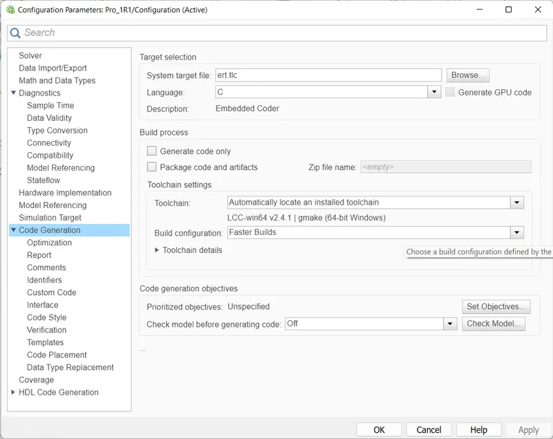
- Code Generation Profile must be in Embedded Coder.
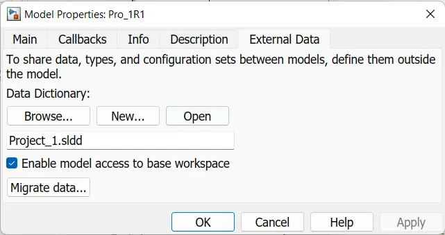
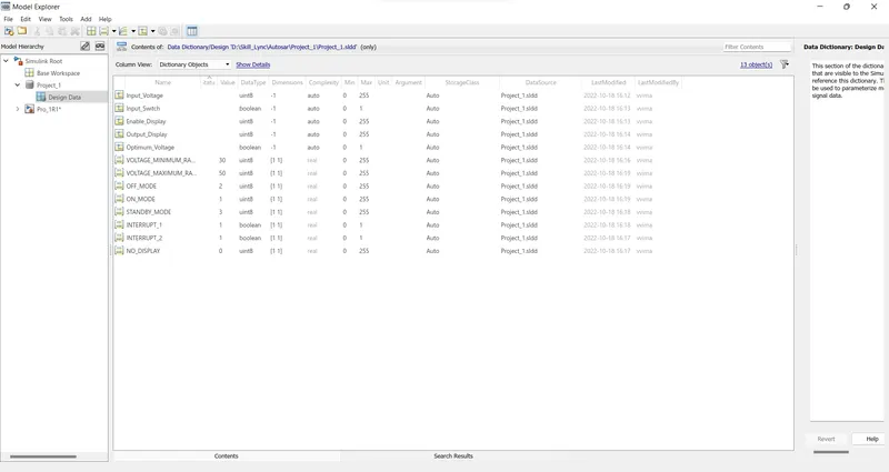
- Simulink Data Dictionary must be created for the model & must be linked to the model.
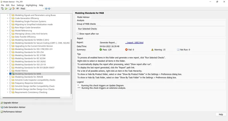
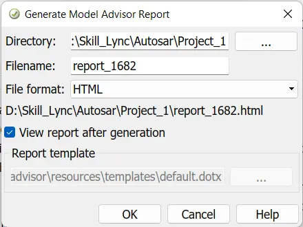
- Model Advisor Report is mandatory & this will be followed by Code Generation.
Input Signals:
|
Name of the Signal |
Data Type |
Range |
|
Input_Voltage |
uint8 |
0 - 255 |
|
Input_Switch |
boolean |
0 – 1 |
|
Enable_Display |
uint8 |
0 - 255 |
Output Signal:
|
Name of the Signal |
Data Type |
Range |
|
Output_Display |
uint8 |
0 - 255 |
Calibration Signals:
|
Name of the Signal |
Data Type |
Range |
Initial Value |
|
VOLTAGE_MINIMUM_RANGE |
uint8 |
0 – 255 |
30 |
|
VOLTAGE_MAXIMUM_RANGE |
uint8 |
0 – 255 |
50 |
|
OFF_MODE |
uint8 |
0 – 255 |
2 |
|
ON_MODE |
uint8 |
0 – 255 |
1 |
|
STANDBY_MODE |
uint8 |
0 – 255 |
3 |
|
INTERRUPT_1 |
boolean |
0 – 1 |
1 |
|
INTERRUPT_2 |
boolean |
0 - 1 |
1 |
|
NO_DISPLAY |
uint8 |
0 – 255 |
0 |
Local Signal:
|
Name of the Signal |
Data Type |
Range |
|
Optimum_Voltage |
boolean |
0 - 1 |
Simulink Data Dictionary must be created for the model & must be linked to the model.
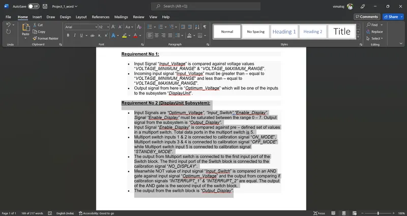
Requirement No 1:
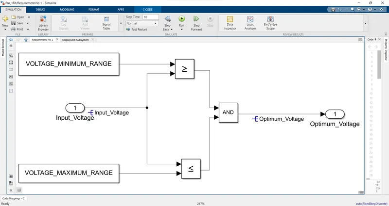
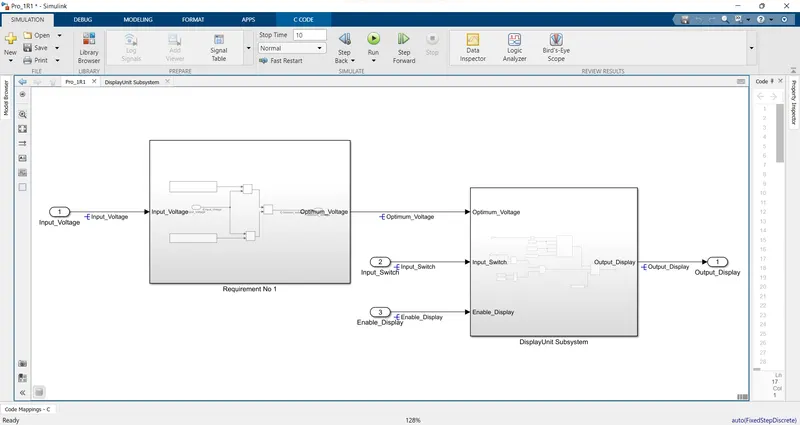
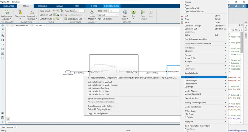
- Input Signal “Input_Voltage” is compared against voltage values “VOLTAGE_MINIMUM_RANGE” & “VOLTAGE_MAXIMUM_RANGE”.
- Incoming input signal “Input_Voltage” must be greater than – equal to “VOLTAGE_MINIMUM_RANGE” and less than – equal to “VOLTAGE_MAXIMUM_RANGE”.
- Output signal from here is “Optimum_Voltage” which will be one of the inputs to the subsystem “DisplayUnit”.
Requirement No 2 (DisplayUnit Subsystem):
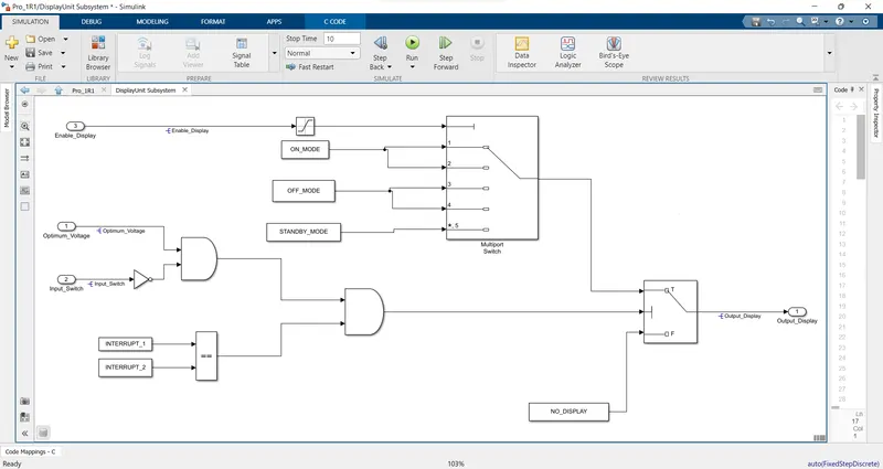
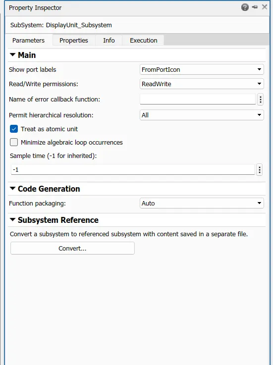
- Input Signals are “Optimum_Voltage”, “Input_Switch”,“Enable_Display”. Signal “Enable_Display” must be saturated between the range 0 – 7. Output signal from the subsystem is “Output_Display”.
- Input Signal “Enable_Display” is compared against pre – defined set of values in a multiport switch. Total data ports in the multiport switch is 5.
- Multiport switch inputs 1 & 2 is connected to calibration signal “ON_MODE”, Multiport switch inputs 3 & 4 is connected to calibration signal “OFF_MODE” while Multiport switch input 5 is connected to calibration signal “STANDBY_MODE”.
- The output from Multiport switch is connected to the first input port of the Switch block. The third input port of the Switch block is connected to the calibration signal “NO_DISPLAY”.
- Meanwhile NOT value of input signal “Input_Switch” is compared in an AND gate against input signal “Optimum_Voltage” and the output from comparing if calibration signals “INTERRUPT_1” & “INTERRUPT_2” are equal. The output of the AND gate is the second input of the switch block.
- The output from the switch block is “Output_Display”.
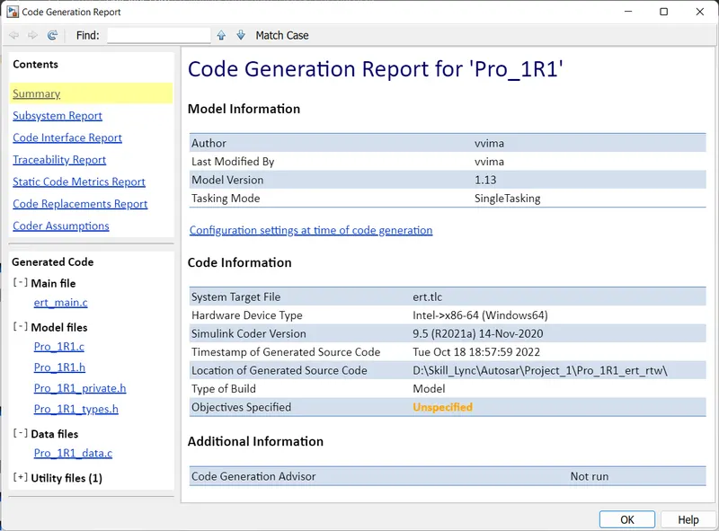
Code Generation Report
File: ert_main.c
1	/*
2	 * File: ert_main.c
3	 *
4	 * Code generated for Simulink model 'Pro_1R1'.
5	 *
6	 * Model version                  : 1.13
7	 * Simulink Coder version         : 9.5 (R2021a) 14-Nov-2020
8	 * C/C++ source code generated on : Tue Oct 18 18:57:59 2022
9	 *
10	 * Target selection: ert.tlc
11	 * Embedded hardware selection: Intel->x86-64 (Windows64)
12	 * Code generation objectives: Unspecified
13	 * Validation result: Not run
14	 */
15
16	#include <stddef.h>
17	#include <stdio.h>              /* This ert_main.c example uses printf/fflush */
18	#include "Pro_1R1.h"                   /* Model's header file */
19	#include "rtwtypes.h"
20
21	/*
22	 * Associating rt_OneStep with a real-time clock or interrupt service routine
23	 * is what makes the generated code "real-time".  The function rt_OneStep is
24	 * always associated with the base rate of the model.  Subrates are managed
25	 * by the base rate from inside the generated code.  Enabling/disabling
26	 * interrupts and floating point context switches are target specific.  This
27	 * example code indicates where these should take place relative to executing
28	 * the generated code step function.  Overrun behavior should be tailored to
29	 * your application needs.  This example simply sets an error status in the
30	 * real-time model and returns from rt_OneStep.
31	 */
32	void rt_OneStep(void);
33	void rt_OneStep(void)
34	{
35	  static boolean_T OverrunFlag = false;
36
37	  /* Disable interrupts here */
38
39	  /* Check for overrun */
40	  if (OverrunFlag) {
41	    rtmSetErrorStatus(Pro_1R1_M, "Overrun");
42	    return;
43	  }
44
45	  OverrunFlag = true;
46
47	  /* Save FPU context here (if necessary) */
48	  /* Re-enable timer or interrupt here */
49	  /* Set model inputs here */
50
51	  /* Step the model */
52	  Pro_1R1_step();
53
54	  /* Get model outputs here */
55
56	  /* Indicate task complete */
57	  OverrunFlag = false;
58
59	  /* Disable interrupts here */
60	  /* Restore FPU context here (if necessary) */
61	  /* Enable interrupts here */
62	}
63
64	/*
65	 * The example "main" function illustrates what is required by your
66	 * application code to initialize, execute, and terminate the generated code.
67	 * Attaching rt_OneStep to a real-time clock is target specific.  This example
68	 * illustrates how you do this relative to initializing the model.
69	 */
70	int_T main(int_T argc, const char *argv[])
71	{
72	  /* Unused arguments */
73	  (void)(argc);
74	  (void)(argv);
75
76	  /* Initialize model */
77	  Pro_1R1_initialize();
78
79	  /* Attach rt_OneStep to a timer or interrupt service routine with
80	   * period 0.2 seconds (the model's base sample time) here.  The
81	   * call syntax for rt_OneStep is
82	   *
83	   *  rt_OneStep();
84	   */
85	  printf("Warning: The simulation will run forever. "
86	         "Generated ERT main won't simulate model step behavior. "
87	         "To change this behavior select the 'MAT-file logging' option.\n");
88	  fflush((NULL));
89	  while (rtmGetErrorStatus(Pro_1R1_M) == (NULL)) {
90	    /*  Perform other application tasks here */
91	  }
92
93	  /* Disable rt_OneStep() here */
94
95	  /* Terminate model */
96	  Pro_1R1_terminate();
97	  return 0;
98	}
99
100	/*
101	 * File trailer for generated code.
102	 *
103	 * [EOF]
104	 */
105
| Model Advisor Report - Pro_1R1.slx | |
| Simulink version: 10.3 | Model version: 1.13 |
| System: Pro_1R1 | Current run: 18-Oct-2022 18:39:48 |
| Treat as Referenced Model: off | |
Run Summary
| Pass | Fail | Warning | Not Run | Total |
|---|---|---|---|---|
 129 129 |
 0 0 |
 15 15 |
 0 0 |
144 |
Modeling Standards for MAB
1 Naming Conventions
19 0 1 0
1.1 General
4 0 0 0
Check file namesCheck the model file name to ensure that the name complies with the recommended guidelines.
Passed
All files have correct names.
Check folder namesCheck the folder name to ensure that the name complies with the recommended guidelines.
Passed
All folders have correct names.
1.2 Content
15 0 1 0
Check subsystem namesIdentify subsystem names with incorrect characters.
Passed
All the subsystem names use correct characters.
Check port block namesIdentify Inport or Outport block names with incorrect characters.
Passed
All the Inport or Outport block names use correct characters.
Check character usage in block namesIdentify block names with incorrect characters.
Passed
All the block names use correct characters.
Check length of Inport and Outport namesCheck length of Inport and Outport names
Passed
All Inport and Outport names are valid.
Check character usage in signal names and bus namesIdentify signal and bus names with invalid characters.
Passed
No invalid characters are used in signal and bus names.
Check character usage in parameter namesIdentify parameter names with invalid characters.
Passed
No invalid characters are used in parameter names.
Check length of signal and bus namesCheck length of signal and bus names
Passed
All signal and bus names are valid.
Check character usage in Stateflow data namesIdentify Stateflow data names with invalid characters.
Passed
No invalid characters are used in Stateflow data names.
Check length of Stateflow data nameCheck if the length of Stateflow data names are within limit.
Passed
All Stateflow data names are valid.
Check duplication of Simulink Data namesSimulink Data names should be unique across base workspace, model workspace and data dictionary.
Passed
All Simulink Data names are unique.
Check unused data in Simulink ModelCheck for unused data in Data Dictionary
Warning
The following data variables in the data dictionary are unused:
| Data Objects | Source |
|---|---|
| Input_Voltage | Project_1.sldd |
| Optimum_Voltage | Project_1.sldd |
| Output_Display | Project_1.sldd |
Recommended Action
Consider removing the unused data variables.
Check for unused data in Stateflow ChartsChecks if the model parameter 'Unused data, events, messages and functions' is not set to 'none'.
Passed
All constraints on model configuration parameters have been met.
| Status | Parameter | Current Value | Recommended Values |
|---|---|---|---|
| Pass | Unused data, events, messages and functions (SFUnusedDataAndEventsDiag) | warning | error, warning |
2 Simulink
49 0 14 0
2.1 Configuration Parameters
4 0 0 0
Check Implement logic signals as Boolean data (vs. double)Identify whether Implement logic signals as Boolean data (vs. double) is selected.
Passed
Implement logic signals as Boolean data (vs. double) is selected.
Check Signed Integer Division Rounding modejc_0642: Integer rounding mode setting
Identifies blocks with block parameter 'Integer Rounding Mode' set to 'Simplest' when the configuration parameter 'Signed integer division rounds to' is set to 'Undefined'.
Passed
Configuration parameter 'Signed integer division rounds to' is not set to 'Undefined'.
Check diagnostic settings for incorrect calculation resultsIdentify data validity diagnostic settings which detect incorrect calculation results.
Passed
All constraints on model configuration parameters have been met.
| Status | Parameter | Current Value | Recommended Values |
|---|---|---|---|
| Pass | Division by singular matrix (CheckMatrixSingularityMsg) | error | error |
| Pass | Inf or NaN block output (SignalInfNanChecking) | error | error |
| Pass | Wrap on overflow (IntegerOverflowMsg) | error | error |
| Pass | Saturate on overflow (IntegerSaturationMsg) | error | error |
2.2 Diagram Appearance
13 0 4 0
Check for Simulink diagrams using nonstandard display attributesIdentify nonstandard display attributes in Simulink diagrams.
_________________________________________________________________________________________
Check format settings
Identify incorrect model-level format options.
Passed
The format options are correct.
_________________________________________________________________________________________
Check block colors
Identify blocks using nonstandard colors.
Passed
All blocks use standard colors.
_________________________________________________________________________________________
Check canvas colors
Identify canvases that are not white.
Passed
All diagrams use a white canvas.
_________________________________________________________________________________________
Check diagram zoom
Identify diagrams that do not have zoom factor set to 100 %.
Note: Zoom factors can differ for each instance of a model diagram opened in Simulink Editor
Warning
The following diagrams do not have zoom factor set to 100 percent:
For each listed diagram, select Modeling > Environment > Zoom > Normal View (100%).
Check Model font settingsIdentify blocks and charts with different font settings from input parameters.
Passed
Font settings of the blocks and charts and input parameters are same.
Check whether block names appear below blocksIdentify blocks where the name is not displayed below the block.
Passed
All blocks have names displayed below the block.
Check the display attributes of block namesIdentify whether to display block names.
Check for blocks with hidden names and obvious function
Identify block names that are displayed but can be hidden due to obvious behavior.
Passed
All blocks with obvious behavior have hidden names.
Check for non-descriptive displayed block names
Identify block names that are displayed but should be hidden due to a lack of a descriptive name.
Passed
All displayed names provide descriptive information.
Check for missing block names
Identify block names that are hidden but should be displayed to show a descriptive name.
Passed
All displayed names provide descriptive information.
Check for nondefault block attributesIdentify blocks that use and fail to display nondefault values.
Warning
The following blocks use and fail to display nondefault values:
| Block | Parameter | Expected Value | Actual Value |
|---|---|---|---|
| Pro_1R1/DisplayUnit_Subsystem/Saturation | UpperLimit | 0.5 | 7 |
| Pro_1R1/DisplayUnit_Subsystem/Saturation | LowerLimit | -0.5 | 0 |
| Pro_1R1/DisplayUnit_Subsystem/Saturation | LinearizeAsGain | on | off |
Recommended Action
For the above blocks, display the nondefault value using the Block Annotation pane of the Block Properties dialog box.
Check Model DescriptionIdentify layers in the model having inconsistent description format.
Warning
Following layers do not have model descriptions:
Consider adding model description for all the layers.
Check if blocks are shaded in the modelCheck if blocks are shaded in the model
Passed
Blocks in the model are not shaded.
Check for unconnected signal lines and blocksIdentify unconnected signal lines, subsystems and basic blocks.
Passed
All signal lines and blocks in the model are connected.
Check signal line connectionsIdentify intersections and overlaps of signals in a model.
Passed
No signal intersections or overlaps found.
Check signal flow in modelIdentify subsystems which do not have a signal flow from left to right.
Warning
The signal flow of diagrams in the following subsystems can be improved:
Ensure that the signal flow in the mentioned subsystems is from left to right.
- All sequential blocks, except the blocks on feedback path, must be placed from left to right.
- All parallel blocks, except the blocks on feedback path, must be placed from top to bottom.
- All blocks should be oriented to the right.
Check usage of tunable parameters in blocksIdentify tunable parameters used to specify expressions, data type conversions, or indexing operations.
Passed
Tunable parameters are not used in the model.
Check connections between structural subsystemsIdentify connections between structural subsystems.
Passed
All connections to structural subsystems adhere to the guideline.
Check for consistency in model element namesCheck if model elements connected to a signal are following consistent naming.
Passed
Model elements connected to a signal are following consistent names.
Check trigger signal namesIdentify trigger blocks where the origin of the trigger signal and the destination have dissimilar names.
Passed
No violation of the guideline for use of trigger signal names.
Check for mixing basic blocks and subsystemsIdentify levels in the model that include basic blocks and subsystems. Each level of a model must be designed with blocks of the same level (for example, only subsystems or only basic blocks).
Passed
The model does not mix basic blocks and subsystems at the same level.
2.3 Signal
2 0 4 0
Check usage of vector and bus signalsIdentify mixed usages of vector and bus signals.
Passed
No mixing of vector and bus signals found in the system.
Check definition of signal labelsIdentify blocks that require labeled signals. A subset of source and destination blocks require labeled signals.
Check source block labels
Warning
The following signals have no label:
- Pro_1R1/Input_Voltage/
- Pro_1R1/DisplayUnit_Subsystem/Optimum_Voltage/
- Pro_1R1/DisplayUnit_Subsystem/Input_Switch/
- Pro_1R1/DisplayUnit_Subsystem/Enable_Display/
- Pro_1R1/Requirement No 1/Input_Voltage/
- Pro_1R1/DisplayUnit_Subsystem/
- Pro_1R1/Requirement No 1/
Add a new or propagated label to the signal line.
_________________________________________________________________________________________
Identify blocks that require labeled signals. A subset of source and destination blocks require labeled signals.
Check destination block labels
Warning
The following signals have no label:
- Pro_1R1/DisplayUnit_Subsystem/Output_Display/
- Pro_1R1/Requirement No 1/Optimum_Voltage/
- Pro_1R1/Output_Display/
- Pro_1R1/DisplayUnit_Subsystem/
- Pro_1R1/Requirement No 1/
Add a new or propagated label to the signal line.
Check Signal name propagationCheck Signal name propagation for subsystems
Warning
The following subsystems do not have propagated signal labels:
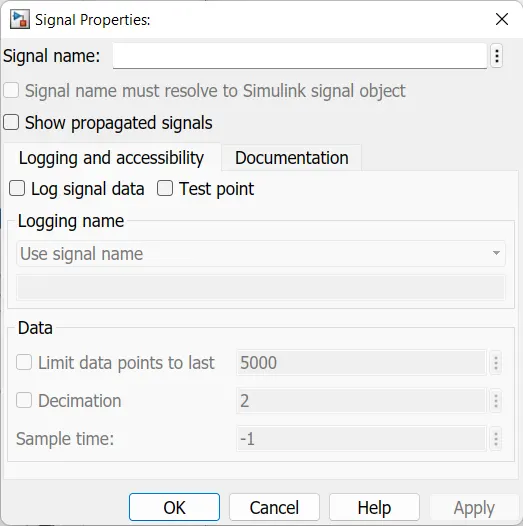
Add labels and enable signal propagation by selecting 'Show propagated signal' parameter for signals.
Check position of signal labelsCheck location of signal labels
Warning
The following signals do not have labels located at the origin of the signal line:
Consider placing the labels at the origin of the signal line.
Check signal line labelsIdentify blocks that require labeled signals. A subset of source and destination blocks require labeled signals.
Check source block labels
Warning
The following signals have no label:
- Pro_1R1/Input_Voltage/
- Pro_1R1/DisplayUnit_Subsystem/Optimum_Voltage/
- Pro_1R1/DisplayUnit_Subsystem/Input_Switch/
- Pro_1R1/DisplayUnit_Subsystem/Enable_Display/
- Pro_1R1/Requirement No 1/Input_Voltage/
- Pro_1R1/DisplayUnit_Subsystem/
- Pro_1R1/Requirement No 1/
Add a new or propagated label to the signal line.
_________________________________________________________________________________________
Identify blocks that require labeled signals. A subset of source and destination blocks require labeled signals.
Check destination block labels
Warning
The following signals have no label:
- Pro_1R1/DisplayUnit_Subsystem/Output_Display/
- Pro_1R1/Requirement No 1/Optimum_Voltage/
- Pro_1R1/Output_Display/
- Pro_1R1/DisplayUnit_Subsystem/
- Pro_1R1/Requirement No 1/
Add a new or propagated label to the signal line.
2.4 Block Consistency
4 0 2 0
Check Indexing ModeCheck for Zero-Based Indexing Mode.
Warning
The following blocks or charts have One-Based Indexing mode:
Consider remodeling by using Zero-Based Indexing.
Check block orientationIdentify blocks which are rotated or reversed.
Passed
No blocks found with rotated or reversed orientation
Check if tunable block parameters are defined as named constantsCheck if tunable block parameters are defined as named constants
Warning
The following tunable block parameters are not defined as named constants.
| Block | Violations |
|---|---|
| Pro_1R1/DisplayUnit_Subsystem/Saturation | UpperLimit : 7 |
Recommended Action
Consider changing tunable block parameter literal values to named constants.
Check for sample time settingCheck if sample time property of a block is set to -1 (inherited).
Passed
All permitted blocks have sample time set to -1 (inherited).
2.5 Conditional Subsystem relations
5 0 0 0
Check position of conditional blocks and iterator blocksIdentify conditional and iterative blocks that are positioned inconsistently in the model.
Passed
The conditional and iterative blocks are correctly placed in the model.
Check undefined initial output for conditional subsystemsIdentify undefined initial output for Outports/Merge blocks in conditional subsystems
Passed
The initial output setting for all Conditional Subsystems are valid.
Check usage of Merge blockjc_0659: Usage restrictions of signal lines input to Merge blocks
There must not be any block between a Conditional Subsystem block and a Merge block.
Passed
No Merge block found.
2.6 Operation Blocks
12 0 3 0
Check fundamental logical and numerical operationsCheck input data types of blocks meant for numerical operations
Warning
The following numerical operation blocks have boolean data type as input:
Consider having non-boolean inputs for the numerical operation blocks.
Check usage of Sum blocksIdentify Sum block usage that can affect readability.
Passed
No violations of the guideline found with the usage of the Sum block.
Check operator order of Product blocksOperator order for Product blocks.
Passed
All Product blocks have valid operator order.
Check signs of input signals in product blocksjc_0611: Input sign for multiplication and division blocks
Identify blocks that perform division whose inputs have different sign bit.
Passed
No product block with division of different sign bits found.
Check for parentheses in Fcn block expressionsIdentify order of parentheses in Fcn block expressions.
Passed
All Fcn blocks use parentheses to mark operator precedence.
Check icon shape of Logical Operator blocksIcon shape of Logical Operator blocks.
Passed
All Logical Operator blocks have consistent icon shape.
Check usage of Relational Operator blocksIdentify Relational Operator blocks that connect to constants with the first (upper) input value.
Passed
All Relational Operator blocks with constant input values are configured correct.
Check comparison of floating point types in Simulinkjc_0800: Comparing floating-point types in Simulink
Equivalence comparison should not be used for floating point numbers.
Passed
No Equivalence comparison done on floating point numbers.
Check usage of Lookup TablesCheck usage of recommended settings for Lookup Table blocks to prevent unexpected results.
Passed
All Lookup Table blocks have recommended settings.
Check usage of Memory and Unit Delay blocksIdentify Memory blocks not using a continuous sample time
Passed
No Memory blocks found with inappropriate sample time
_________________________________________________________________________________________
Identify Unit Delay blocks with non-discrete sample time
Passed
No Unit Delay blocks found with non-discrete sample time
Check for cascaded Unit Delay blocksIdentify cascaded and tapped pattern of Unit Delay blocks.
Passed
No cascaded Unit Delay blocks found that can be changed to Tapped Delay/Delay block.
Check usage of Discrete-Time Integrator blockCheck usage of recommended settings for Discrete-Time Integrator blocks to prevent unexpected results.
Passed
All Discrete-Time Integrator blocks have recommended settings.
Check usage of the Saturation blocksjc_0628: Usage of Saturation blocks
Identify the Saturation and Saturation Dynamic blocks that perform type casting.
Warning
The blocks listed below have one or more of the following issues -
1. For Saturation block, Output data type property is not set to "Inherit: Same as input".
2. For Dynamic Saturation block, Output data type property is not set "Inherit: Same as second input".
3. For Saturation block, upper limit of input signal is not set to less than the maximum value of the output data type.
4. For Saturation block, lower limit of input signal is not set to more than the minimum value of the output data type.
Perform following actions for Saturation and Dynamic Saturation blocks -
1. For Saturation block, set Output data type property to "Inherit: Same as input"
2. For Dynamic Saturation block, set Output data type property to "Inherit: Same as second input"
3. For Saturation block, set upper limit of input signal to less than the maximum value of the output data type.
4. For Saturation block, set lower limit of input signal to more than the minimum value of the output data type.
Check output data type of operation blocksjc_0651: Implementing a type conversion
Identify operation blocks that specify output data type.
Warning
Following operation blocks explicitly specify output data type:
- Pro_1R1/DisplayUnit_Subsystem/AND
- Pro_1R1/DisplayUnit_Subsystem/AND1
- Pro_1R1/DisplayUnit_Subsystem/NOT
- Pro_1R1/DisplayUnit_Subsystem/Relational Operator
- Pro_1R1/Requirement No 1/Logical Operator
- Pro_1R1/Requirement No 1/Relational Operator
- Pro_1R1/Requirement No 1/Relational Operator1
Instead of explicitly specifying output data type on operation blocks, use 'Data Type Conversion' block when changing the data type of the block output signal.
2.7 Other blocks
9 0 1 0
Check position of Inport and Outport blocksCheck positions of Inport blocks
Warning
The following Inport blocks are not placed to the extreme left side of the diagram:
Move the Inport blocks identified to the left of all other blocks in the diagram.
It is acceptable to move the Inport block to the right only to prevent signal crossings.
Check display for port blocksIdentify Inport and Outport blocks that do not specify Port number for the Icon display block parameter.
Passed
All port blocks display the port number.
Check scope of From and Goto blocksIdentify incorrect scoping of From and Goto blocks. For signal flows, From and Goto blocks must use local scope. Control flow can use global scope.
Passed
All From and Goto blocks are used correctly.
Check for usage of Data Store Memory blocksIdentify the usage of Data Store Memory blocks.
Passed
Usage of Data Store Memory blocks is correct.
Check usage of Switch blocksIdentify Switch blocks that do not use Boolean inputs for the switch condition (input 2), and do not use u2 ~= 0 for the Criteria for passing first input block parameter.
_________________________________________________________________________________________
Check Switch block parameters
Identify Switch blocks with the parameter Criteria for passing first input not set to u2 ~= 0.
Passed
The block parameter Criteria for passing first input is correctly configured.
_________________________________________________________________________________________
Check for Boolean switch condition
Identify blocks that do not use Boolean signal switch conditions (input 2).
Passed
The switch condition is a Boolean signal.
Check input and output datatype for Switch blocksIdentify Switch blocks with mismatched input and output data types.
Passed
No Switch blocks found with mismatched input and output data types
Check settings for data ports in Multiport Switch blocksIdentify Multiport Switch blocks that violate data port settings.
Passed
No Multiport Switch blocks found with inappropriate data port settings.
Check for missing ports in Variant SubsystemsCheck for number of inputs/outputs to a Variant Subsystem.
Passed
No Variant Subsystems found having different number of inputs/outputs in the Variant Subsystem choices.
3 Stateflow
52 0 0 0
3.1 Block/Data/Events
7 0 0 0
Check for Strong Data Typing with Simulink I/OCheck whether labeled input and output signals are strongly typed.
Passed
No Stateflow charts have Use Strong Data Typing with Simulink I/O cleared.
Check for names of Stateflow ports and associated signals
Identify mismatches between names of Stateflow ports and the associated signals.
Passed
No Stateflow charts were found.
Check execution timing for default transition path'Execute (enter) Chart At Initialization' should be set to OFF.
Passed
All Stateflow Charts pass the check.
Check definition of Stateflow dataIdentify the Scope value set on Stateflow data defined at machine level.
Passed
All Stateflow data at machine level has been defined as per guideline.
Check usable number for first indexIdentify usage of first index of Stateflow data.
Passed
All Stateflow data first index values are uniform.
3.2 Diagram
14 0 0 0
Check for unconnected objects in Stateflow ChartsIdentify dangling transitions and unconnected Stateflow States and Junctions in Stateflow Charts.
Passed
No unconnected transitions, states or junctions found in Stateflow Charts.
Check for exclusive states in state machinesIdentify states which are the only sub-state within a state with OR(exclusive) type decomposition.
Passed
All states with OR(exclusive) type decomposition have more than one sub-state.
Check usage of parallel statesSubstates of parallel states should not be parallel states.
Passed
All Stateflow Charts pass the check.
Check Stateflow transition appearanceIdentify Stateflow transitions visually overlapping other Stateflow objects.
Passed
No transition violates the guidelines for Stateflow transition appearance.
Check default transition placement in Stateflow chartsjc_0531: Default transition
Identify all groupings of states that do not have a default transition or do not have the default state as the top-most state.
Passed
No Stateflow transitions and states found that violate the guidelines for default transition placement in Stateflow charts.
Check usage of transitions to external statesIdentify transitions ending on external child states.
Passed
No direct transitions found from external state to child state.
Check for unexpected backtracking in state transitionsIdentify configuration parameter settings which identify unexpected backtracking in state transitions.
Passed
All constraints on model configuration parameters have been met.
| Status | Parameter | Current Value | Recommended Values |
|---|---|---|---|
| Pass | Unexpected backtracking (SFUnexpectedBacktrackingDiag) | error | error |
Check usage of internal transitionInternal transition lines should start from the left edge of the state.
Passed
No Stateflow transitions found that violate the guidelines for starting point of internal transition in Stateflow.
Check usage of internal transitions in Stateflow statesIdentify Stateflow states using multiple internal transitions.
Passed
No Stateflow states found with multiple internal transitions
Check prohibited combination of state action and flow chartState actions and flow charts should not be combined in states.
Passed
No Stateflow states were found that combine state action and flow chart.
Check transitions in Stateflow flow chartsIdentify transitions in Stateflow flow charts that are drawn incorrectly.
Passed
All Stateflow transitions in flow charts are drawn correctly.
Check usage of unconditional transitions in flow chartsIdentify unconditional transitions in flow charts.
Passed
All unconditional transitions adhere to the guideline.
3.3 Condition Transition/Action
17 0 0 0
Check Stateflow chart action languageCheck if the action language of Stateflow charts is set to 'C'.
Passed
All Stateflow Charts have action language set to 'C'.
Check usage of numeric literals in StateflowIdentify use of numeric literals in Stateflow states and transitions.
Passed
No numeric literals found in Stateflow charts.
Check for pointers in Stateflow chartsIdentify pointer operations on custom code variables.
Note: This check applies only to Stateflow charts that use C as the action language.
Passed
No pointer operations were found.
Check usage of events in Stateflow chartsIdentify undirected event broadcasts in Stateflow.
Passed
No instances of undirected event broadcast were found.
Check order of state action typesIdentify out of order state action types in Stateflow states.
Passed
No Stateflow states found with out of order state action types
Check repetition of Action typesjc_0734: Number of state action types
Identifies repeated action types in a Stateflow State.
Passed
No Stateflow States were found.
Check if state action type 'exit' is used in the modelCheck if state action type 'exit' is used in the model.
Passed
State action type 'exit' is not used in the model.
Check updates to variables used in state transition conditionsjc_0741: Timing to update data used in state chart transition conditions
Variables used in state transition conditions must not perform an update by "during" state action type.
Passed
No Stateflow states found that violate the guidelines for updating the variables used in state transition conditions.
Check usage of transition conditions in Stateflow transitionsIdentify unconditional Stateflow transitions with higher priority than conditional transitions.
Passed
No unconditional Stateflow transitions found with higher priority than conditional transitions
Check condition actions and transition actions in StateflowIdentify usage of transition actions in Stateflow.
Passed
No Stateflow charts have transition actions.
Check for MATLAB expressions in Stateflow blocksIdentify MATLAB expressions that are not suitable for code generation in Stateflow blocks.
Passed
No Stateflow objects found using MATLAB expressions unsuitable for code generation.
Check usage of floating-point expressions in Stateflow chartsIdentify equality or inequality operations (==,~=,!=) in expressions involving floating-point variables or constants.
Passed
No equality or inequality to operations in expressions where at least one side of the expression is a floating-point variable or constant were found.
Check Stateflow operatorsIdentify the usage of operators in Stateflow.
Passed
No Stateflow blocks found with incorrect operator usage.
Check prohibited comparison operation of logical type signalsIdentify boolean variables in Stateflow charts using comparison operations.
Passed
No boolean variables use comparison operations of logical type in the model.
Check usage of unary minus operations in Stateflow chartsIdentify unary minus operations applied to unsigned integers in Stateflow objects.
Passed
No unary minus operations applied to unsigned integers in Stateflow objects were found.
3.4 Label Description
10 0 0 0
Check uniqueness of Stateflow State and Data namesjc_0732: Distinction between state names, data names, and event names
Identify Stateflow State and Stateflow Data that have identical names in a given chart.
Passed
No Stateflow charts were found.
Check uniqueness of State namesjc_0730: Unique state name in Stateflow blocks
Identifies identical State names within a Stateflow Chart.
Passed
No Stateflow charts were found.
Check usage of State namesjc_0731: State name format
Identify state names with '/' at its end.
Passed
No Stateflow states were found.
Check entry formatting in State blocks in Stateflow chartsIdentify missing line breaks between entry action (en), during action (du), and exit action (ex) entries in states. Identify missing line breaks after semicolons (;) in statements.
Passed
All state entries found are correctly formatted.
Check indentation of code in Stateflow statesIdentify non-uniform indentation in Stateflow blocks.
Passed
All Stateflow blocks have uniform indentation.
Check for usage of text inside statesIdentify Stateflow states with text exceeding the boundary of the state.
Passed
No Stateflow states found with text exceeding the boundary of the state.
Check position of label string in Stateflow transitionIdentify placement of label string in Stateflow transition.
Passed
All Stateflow transitions are placed uniformly.
Check position of comments in transition labelsIdentify comments in transition labels that are not positioned uniformly.
Passed
Comments in transition labels are positioned uniformly.
3.5 Miscellaneous
4 0 0 0
Check return value assignments in Stateflow graphical functionsIdentify graphical functions with multiple assignments of return values in Stateflow charts.
Passed
No Stateflow charts were found.
Check uniqueness of Stateflow State and Data namesjc_0732: Distinction between state names, data names, and event names
Identify Stateflow State and Stateflow Data that have identical names in a given chart.
Passed
No Stateflow charts were found.
4 MATLAB
9 0 0 0
4.1 Data and Operations
3 0 0 0
Check MATLAB code for global variablesCheck for global variables in MATLAB code
_________________________________________________________________________________________
Check for global variables in MATLAB code used in MATLAB Function blocks
Passed
No MATLAB Function blocks found
_________________________________________________________________________________________
Check for global variables in MATLAB functions defined in Stateflow charts
Passed
No MATLAB functions defined in Stateflow charts found
_________________________________________________________________________________________
Check for global variables in called MATLAB functions
Passed
No external MATLAB functions found
_________________________________________________________________________________________
4.2 Usage
6 0 0 0
Check lines of code in MATLAB FunctionsIdentify MATLAB Functions with high number of effective lines of code.
Passed
No MATLAB Function found with high number of effective lines of code.
Check the number of function calls in MATLAB Function blocksChecks whether number of function calls in MATLAB Function blocks is less than 3.
Passed
Number of function calls in MATLAB Function blocks is less than 3.
Check nested conditions in MATLAB FunctionsIdentify nested if/else and case statements in MATLAB Functions.
Passed
No MATLAB Function found with deeply nested if/else and case statements.
Check usage of character vector inside MATLAB Function blockChecks whether character vectors are being used inside MATLAB Function blocks
Passed
No character vectors found in MATLAB Function block