Project 1 - Simulating a BTMS
AIM
The aim of this project is to simulate the flow inside a Battery Thermal Management System
OBJECTIVES
The main objectives are as follows
1.Excel Calculator for Volumetric heat generation source
2. Run the case for different mesh sizes - 12,8,6 and 4 mm
3. Effect of element length on accuracy of results
EXCEL CALCULATOR :
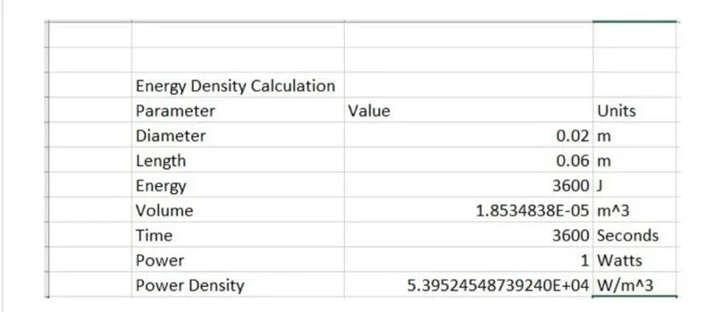
Since an Amp Hour (Ah) is a measure of charge (measured in "Coulombs") whereas a Joule is a measure of energy, you can't convert mAh to Joules without first knowing the voltage (Volts) a which the charge was transferred. Given that voltage the conversion is just:
Charge (C) x Voltage (V) = Energy (1)
and,
Current (A) x time (seconds) = Charge (C)
To find the mAh to Joule conversion we first find the charge in a mAh.
mA means 1/1000 of an Amp for an hour and there are 60 x 60 = 3600 seconds per hour. So,
ImAh = 0.001 Amps x 3600 seconds = 3.6 Coulombs of charge. Choosing 1 Volts for the voltage, we can now convert mAh to Joules.
3.6 (C) x 1 (V) = 3.6 (J)
We say at 1 Volts, 1mAh of charge equals 3.6 Joules of energy. This is a handy value for mAh to Joule conversions.
For any voltage, mAh X voltage x 3.6 = Joules of energy.
For example. A 7.2 Volt battery that delivers 100 mAh of charge has delivered,
100 x 7.2 x 3.6=2592 Joules of energy.
As we saw above, since a mAh is 1/1000 of an Ah, to convert Ah (amp hours) to
Joules just use 1000 x 3.6=3600 as the conversion factor instead of 3.6. An Amp Hour (Ah) is a measure of charge (measured in "Coulombs") whereas a Watt Hour (Wh) is a measure of energy. The two are related by voltage. So a 36 V battery
stores twice the energy (Wh) of an 18 V battery.
When only an Ah specification is given it is understood that the voltage that determines the energy this represents is that of the battery (storage device).
In summary, the energy (measured in "Joules") stored in a 36 V, 15 Ah (15,000 mAh) battery is 36x15 540 "Volt-Amp-hours" or Watt-hours. Where a Volt-Amp-hour (Wh) is 3600 Joules (J). So our battery has stored 1,944,000 Joules of energy!
That's pretty close to the -2,110,000 Joules in a stick of dynamite? A good reason to respect storage batteries!
BATTERY THERMAL MANAGMENT SYSTEM SIMULATION CASE 1 :
Now for the simulation of BTMS we have to follow these steps
• Geometry
• Mesh
• Solution
• Setup
• Results
Geometry.
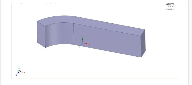
This is the CAD model of a made up BTMS which contains 5 cells which is enclosed in the fluid volume and air is cooling fluid which is being ciculated around the battery.
MESH :
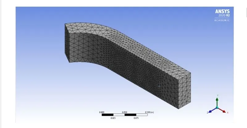
Now here an element size of 12mm is used which takes the count of the number of elements to 85127 elements. The tetrahedral mesh is used for the fluid volume. But when we say that the cell is a solid zone it creates ordinary mesh.
Setup :
1. Solver-Density solver 2. Solver state-Steady state
3. turbulence Model - K-Epsilon Model 4. Inlet Velocity = 4m/s
5. Volumetric Heat source= 30000 W/m^3
6. Outlet Pressure = 0 Pascals
While simulating the BTMS, it is not fine to use any solid material because the battery manufacturer would have specified the material that is being used for the battery. cells. But for the simulation purpose it should be seen that the material should have certain thermal properties to conduct the heat easily to the cooling liquid in the battery pack
During the previous derivation of 1D heat energy balance equation we see the terms like thermal conductivity and heat generation term.
Residual Plot :
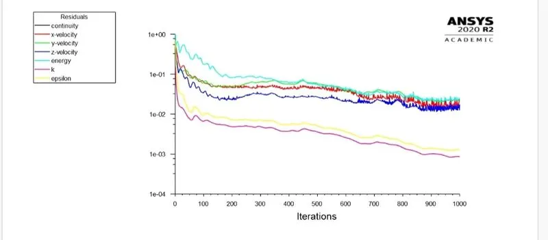
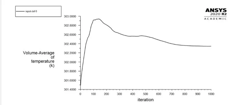
Now here the simulation was run for 1000 iterations and we observe that the solution has converged after 900 iterations
Volume Average Temperature plot :
Results :
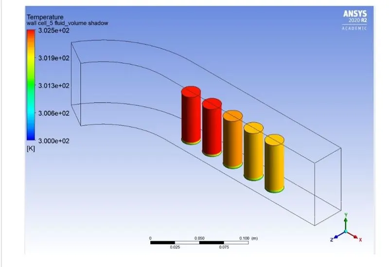
Temperature contour of cells :
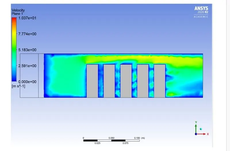
Velocity contour plot :
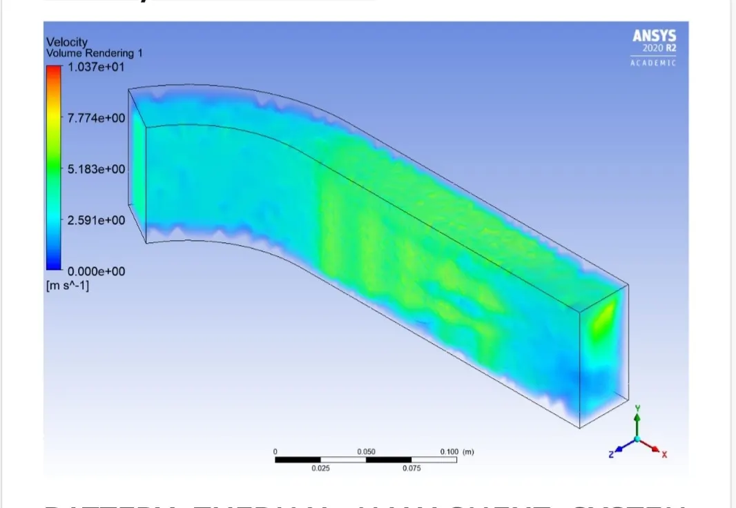
Velocity volume render :
BATTERY THERMAL MANAGMENT SYSTEM SIMULATION-CASE 2
Now for the simulaton of BTMS we have to follow these steps
1.Geometry
2.Mesh
3.Solution
4.Setup
5.Results
Geometry :
This is the CAD model of a made up BTMS which contains 5 cells which is enclosed in the fluid volume and air is cooling fluid which is being circulated around the battery.
MESH :
Now here an element size of 8mm is used which takes the count of the number of elements to 85127 elements. The tetrahedral mesh is used for the fluid volume. But when we say that the cell is a solid zone it creates ordinary mesh.
Setup
1. Solver-Density solver
2. Solver state - Steady state
3. turbulence Model - K-Epsilon model
4. Inlet Velocity = 4m/s
5. Volumetric Heat source= 30000 W/m^3
6. Outlet Pressure = 0 Pascals
While simulating the BTMS, it is not fine to use any solid material because the battery manufacturer would have specified the material that is being used for the battery cells. But for the simulation purpose it should be seen that the material should have certain thermal properties to conduct the heat easily to the cooling liquid in the battery pack
During the previous derivation of 1D heat energy balance equation we see the terms
like thermal conductivity and heat generation term.
Residual Plot :
Now here the simulation was run for 1000 iteration and we observe that the solution has converged after 900 iterations
Volume average temperature plot :
Results :
Temperature contour of cells :
Velocity contour plot :
Velocity volume render :BATTERY THERMAL MANAGMENT SYSTEM SIMULATION-CASE 3
Now for the simulaton of BTMS we have to follow these steps
1.Geometry
2.Mesh
3.Solution
4.Setup
5.Results
Geometry:
This is the CAD model of a made up BTMS which contains 5 cells which is enclosed in the fluid volume and air is cooling fluid which is being circulated around the battery.
Mesh:
Now here an element size of 6mm is used which takes the count of the number of elements to 85127 elements. The tetrahedral mesh is used for the fluid volume. But when we say that the cell is a solid zone it creates ordinary mesh.
Setup
1. Solver-Density solver
2. Solver state - Steady state.
3. turbulence Model - K-Epsilon Model
4. Inlet Velocity = 4m/s
5. Volumetric Heat source= 30000 W/m^3
6. Outlet Pressure = 0 Pascals
While simulating the BTMS, it is not fine to use any solid material because the battery manufacturer would have specified the material that is being used for the battery cells. But for the simulation purpose it should be seen that the material should have certain thermal properties to conduct the heat easily to the cooling liquid in the battery pack
During the previous derivation of 1D heat energy balance equation we see the terms like thermal conductivity and heat generation term.
Residual Plot :
Now here the simulation was run for 1000 iterations and we observe that the solution has converged after 900 iterations
Volume Average Temperature plot :
Results :
Temperature contour of cells :
Velocity contour plot :
Velocity volume render :BATTERY THERMAL MANA SYSTEM SIMULATION-CASE 4 :
Now for the simulaton of BTMS we have to follow these steps
1.Geometry
2.Mesh
3.Solution
4.Setup
5.Results
Geometry:
This is the CAD model of a made up BTMS which contains 5 cells which is enclosed in the fluid volume and air is cooling fluid which is being circulated around the battery.
Mesh
Now here an element size of 4mm is used which takes the count of the number of elements to 85127 elements. The tetrahedral mesh is used for the fluid volume. But when we say that the cell is a solid zone it creates ordinary mesh.
Setup
1. Solver-Density solver
2. Solver state - Steady state
3. turbulence Model - K-Epsilon model
4. Inlet Velocity = 4m/s
5. Volumetric Heat source = 30000 W/m^3
6. Outlet Pressure = 0 Pascals
While simulating the BTMS, it is not fine to use any solid material because the battery. manufacturer would have specified the material that is being used for the battery cells. But for the simulation purpose it should be seen that the material should have certain thermal properties to conduct the heat easily to the cooling liquid in the battery pack.
During the previous derivation of 1D heat energy balance equation we see the terms like thermal conductivity and heat generation term.
Residual Plot :
Now here the simulation was run for 1000 iterations and we observe that the solution has converged after 900 iterations
Volume Average Temperature plot :
Result :
Temperature contour of cells :
Velocity contour plot :
Velocity volume render :SIMULATION ACCURACY :
When we compare all the 4 cases of the residual plot, and the various contour plots, we can observe that if we refine the mesh to fine level we see an increase in the accuracy of the results. But after a certain mesh size the accuracy almost remains constant
CONCLUSION :
1. The flow over a BTMS is performed
2.The heat generation source term was derived based on battery specifications
3. The mesh size was varied and we see that there is a slight improvements in the results and plots.