Project 1 - Review of Shear & Moment Connections in RAM Connection
Question. Design and optimize typical shear, moment and Splice joints in RAM Connection for the following structure modelled in Staad Pro. Design and optimize base plate connection.
Structure: A 2D portal frame fixed support spanning 15m with a pitched roof ridge height of 12m, slope of 4 degrees. A uniformly distributed load of 10kN/m is applied on the roof beams. Optimize the beams and columns for 85% utilization and consider splice joints at 6m from base and 4m from beam column joints. Consider a hanger beam shear connected with column support of 4m height from the splice joint with a length of 3m from beam-column corner joint carrying 5kN/m load. Use hot rolled sections.
Solution:
AIM: To design and optimize typical shear,moment and Splice joint in RAM connections for the following structure Staad Pro.
Structure: A 2D portal frame fixed support spanning 15m with a pitched roof ridge height of 12m, slope of 4 degrees. A uniformly distributed load of 10kN/m is applied on the roof beams. Optimize the beams and columns for 85% utilization and consider splice joints at 6m from base and 4m from beam column joints. Consider a hanger beam shear connected with column support of 4m height from the splice joint with a length of 3m from beam-column corner joint carrying 5kN/m load. Use hot rolled sections.
Given Data:
|
Fixed. |
|
15m. |
|
Pitched Roof. |
|
12m. |
|
4 degree. |
|
10kN/m UDL. |
|
At 6m. |
|
Shear connected with column support of 4m height from splice joint with a length of the 3m with a beam column corner joint carrying 5kN/m load. |
PROCEDURE:
- So the very first step in design the typical shear, moment and splice joint in the STAAD Pro software, Open the staad.pro and make a portal frame
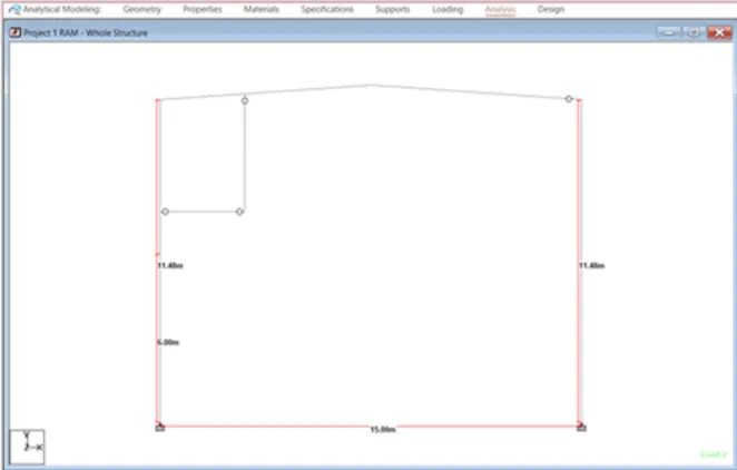
- Create the 2D portal frame as per given data and loading in the above question just as shown in the below given image:
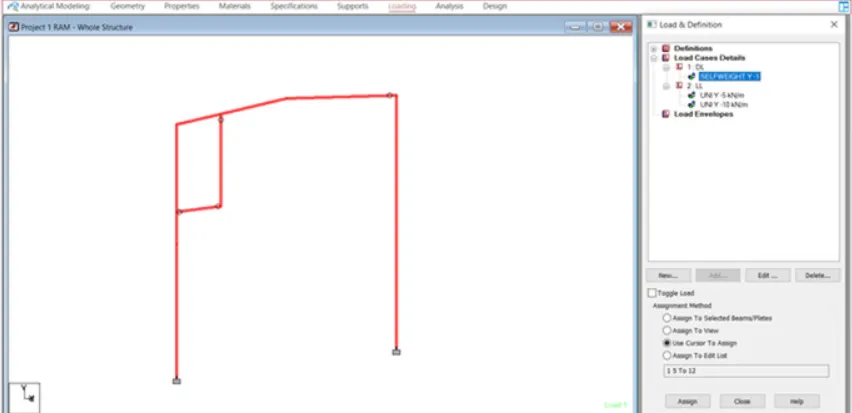
- Next go to the Loading ribbon and apply the self-weight in the form of Dead load and assign the load to the frame just as shown in the below given image:
- Now assign the Live loading of 10 kN/m as the UDL on roof beam just as shown in the below given image:
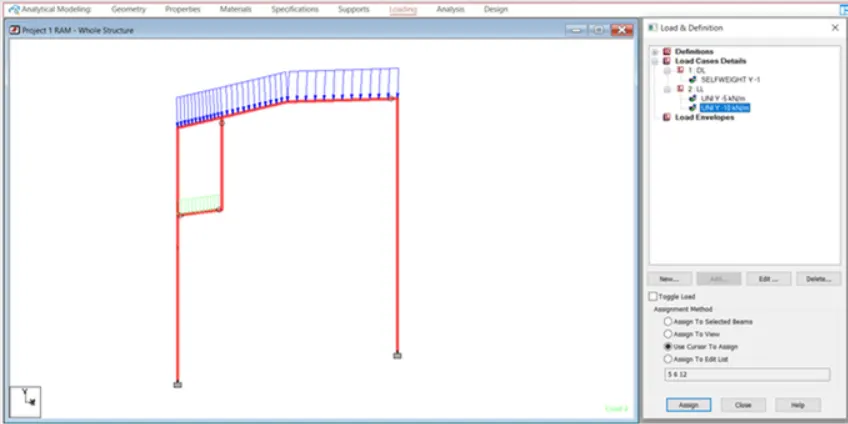
- Live load of 5 Kn/m as UDL on hanger beam is assigned just as shown in the below given image:
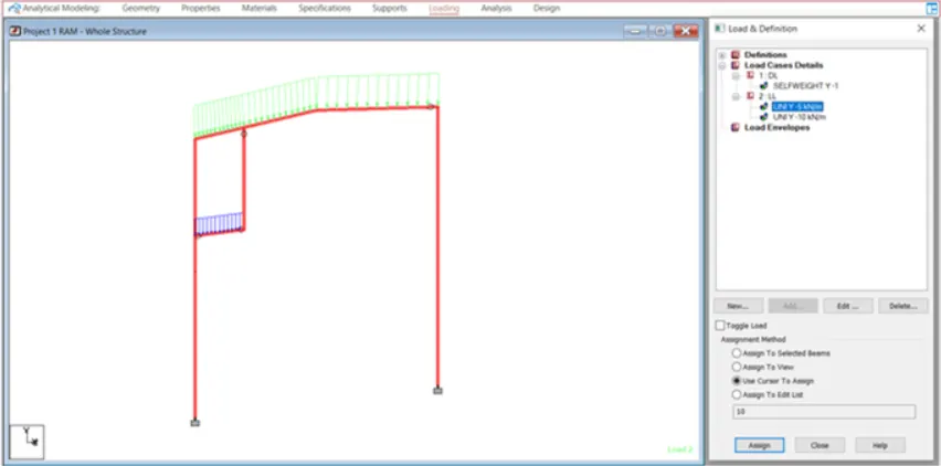
- Our 2D frame is ready below is the given image of the 3D view of 2D portal frame:
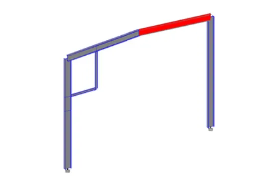
- Shear, moment and splice joints are created as shown in the below given image:
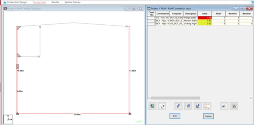
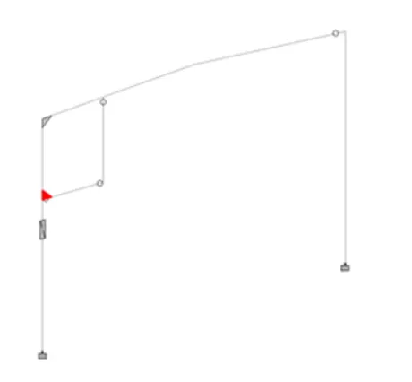
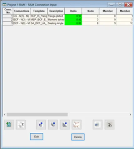
- Bolted splice flange plate joint is between member 1 & 8 at node 7. Beam column flange bolted moment joint is between member 5 & 9 at node 3. Beam column flange seating angle shear connection at node 8 between member 9 &10 as we can see in the above given image:
- Above steps are common to all the other joints so shall not be repeated, do the same procedures for the remaining joints.
Design - 1st Joint:
- The very first step in order to design the seating angle bolted BCF joint go to the RAM connection software, go to the Home page and in that Home page there will be a New ribbon tab under the Home tab just click on that option just as shown in the below given image:

- After that there will be a new dialouge box named as the New Joint opens just as shown in the below given image:
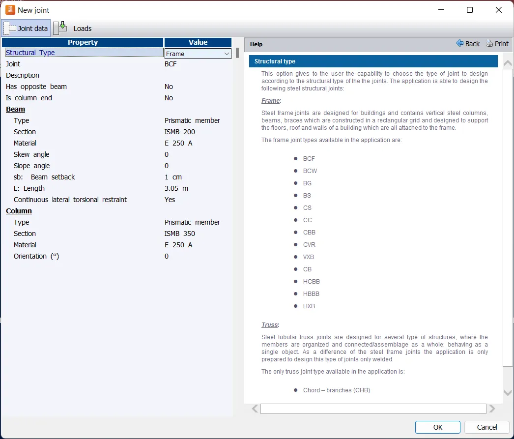
- Next is to select the joint type, Structural Type, Material of the beam and column, Type of beam and column, Section of beam and column etc and hit OK just as shown in the below given image:
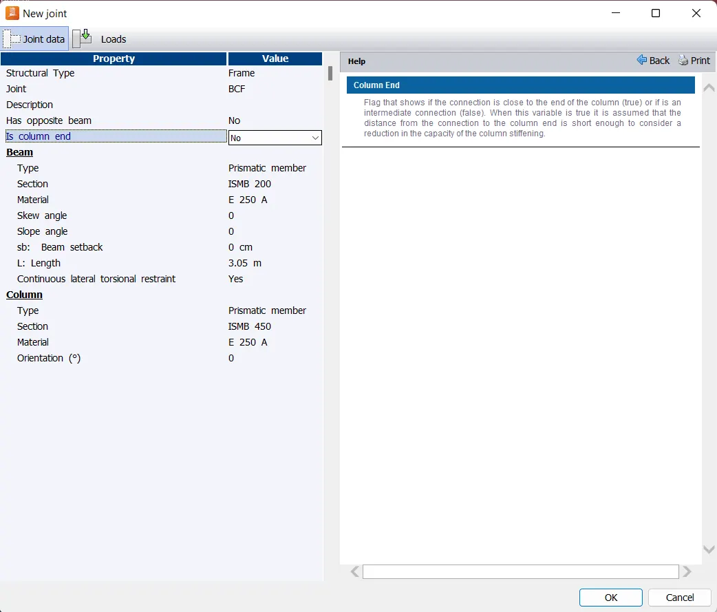
- The joint has been created just as shown in the below given image:
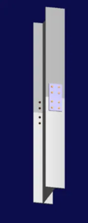
- Next we are going to define the Load conditions, and in order to do that go to the Load Conditions sub-ribbon under Home tab there will be an option named as the Add/Edit just click on that option just as shown in the below given image:

- Next there will be a dialouge box opened named as the Load Conditions, generate the Load cases and the combinations according to the scenario just as shown in the below given image:
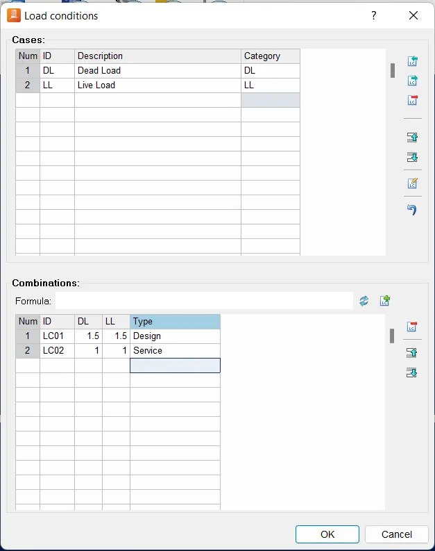
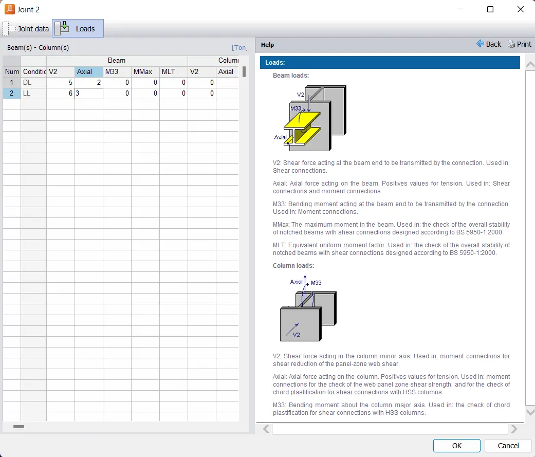
- Next we will be assigning the Loads, and in order to assign the Loads go to the Joints sub-ribbon under Home tab there will be an option named as the Edit just click on that option just as shown in the below given image:

- Next there will be another dialouge box named as the New Joint opens, in that dialouge box fill out the details accordingly and hit OK just as shown in the below given image:
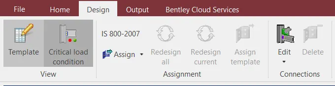
- Next go to the View sub-ribbon tab under Design ribbon tab there will be an option named as the Template just hit on that button just as shown in the below given image:
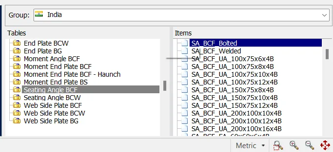
- After which we can select the intended joint for this particular example, first we need to select the group i.e, India and after selecting the group we need to scroll down to the appropriate table to select clip angle joint for this particular connections like Seating Angle BCF table next from the Items section select SA_BCF_Bolted just as shown in the below given image:
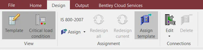
- Next we have to assign this template to the joint and in order to do that go to the Assignment sub-ribbon under Design ribbon tab there will be an option named as the Assign template just hit that button as shown in the below given image:
- Next the joint has been created just as shown in the below given image:
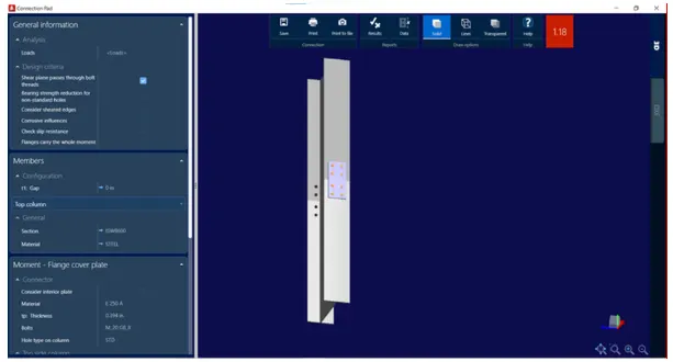
- Bolted splice flange plate joint is between member 1 & 8 at node 7 just as shown in the below given image:
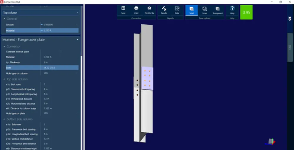
- Design of Bolted splice flange plate joint is designed as shown in the below given image in which utilisation ratio is 0.95 < 1.0:
Report- Data and DXF Details:
DXF Details:
- On the right hand side of the screen there is an option named as the DXF, just click on that option just as shown in the below given image:

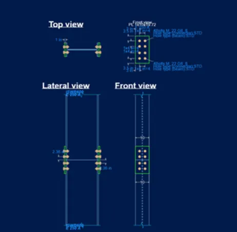
- After selecting the DXF, it gives us the drafting view the Top View, Lateral View and the Front View of the connections just as shown in the below given image:
Report Details:
- So next we will review the results for the joint and in order to view the report or the result there will be an option named as the Data just as shown in the below given image:

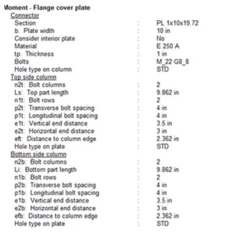
- Below is the result :
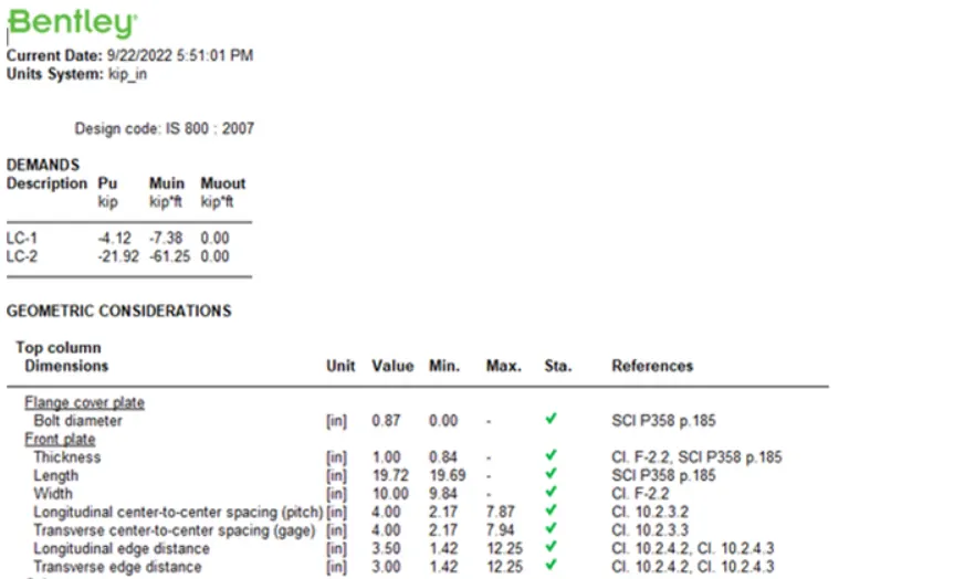
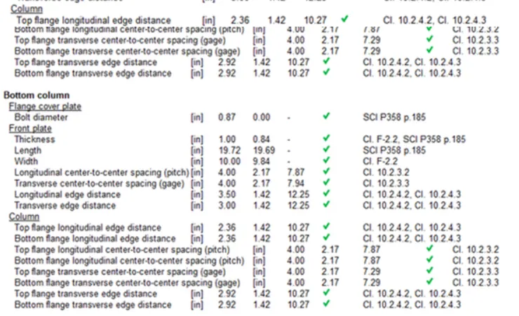
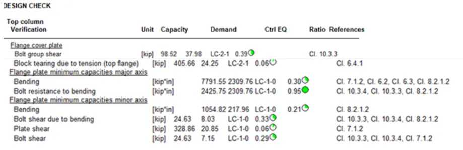
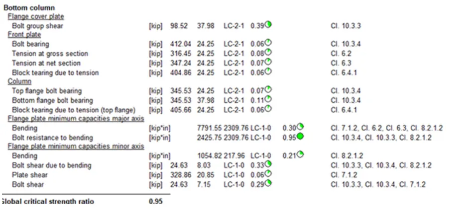
- So next we will review the results for the joint and in order to view the report or the result there will be an option named as the Results just as shown in the below given image:

- Below is the result:
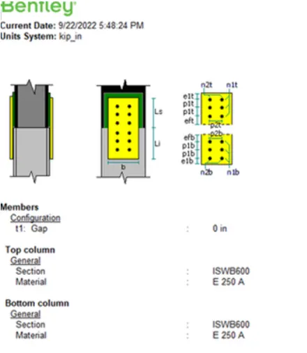
Design - 2nd Joint:
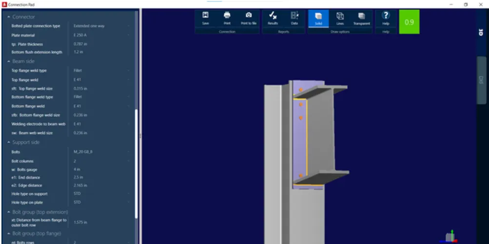
- Beam column flange bolted moment joint is between member 5 & 9 at node 3:
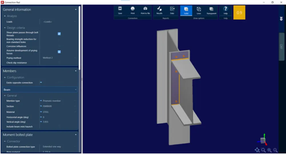
- Design of Beam column flange bolted moment joint is between member 5 & 9 at node 3 is as shown in the below given image in which utilisation ratio is 0.9 <1.0 ( safe):
DXF Details:
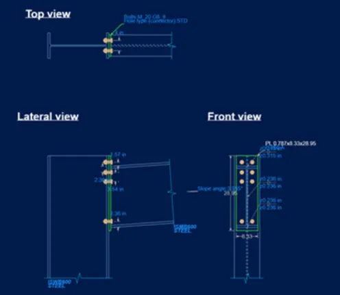
- On the right hand side of the screen there is an option named as the DXF, just click on that option just as shown in the below given image:
- After selecting the DXF, it gives us the drafting view the Top View, Lateral View and the Front View of the connections just as shown in the below given image:
Design -3rd Joint:
- Beam column flange seating angle shear connection at node 8 between member 9 &10 as shown in the below given image:
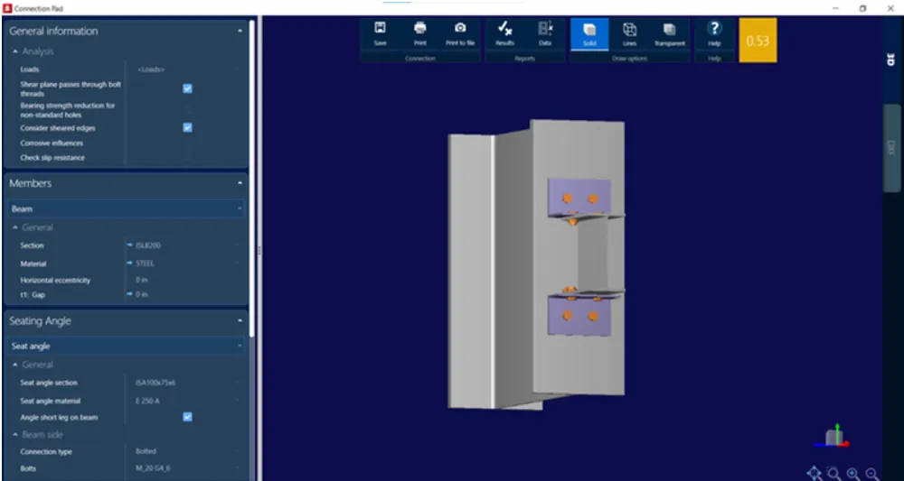
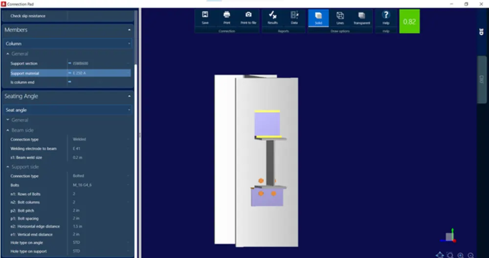
- Design of Beam column flange seating angle shear connection at node 8 between member 9 &10 as shown in the below given image:
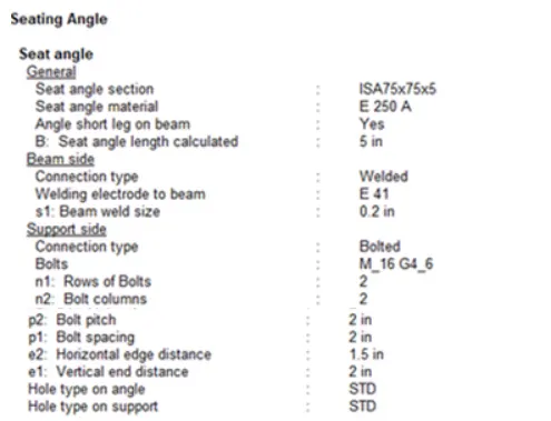
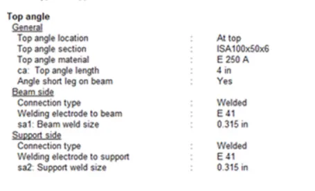
Report and Data Details:
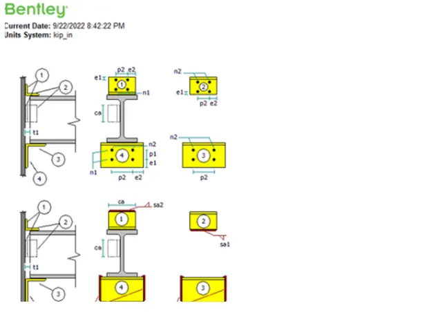
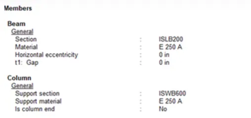
- So next we will review the results for the joint and in order to view the report or the result there will be an option named as the Data just as shown in the below given image:
- Below is the result :
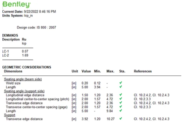
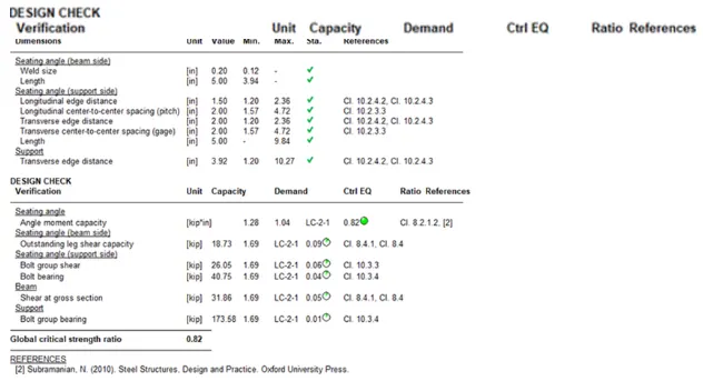
- So next we will review the results for the joint and in order to view the report or the result there will be an option named as the Results just as shown in the below given image:
- Below is the result:
-
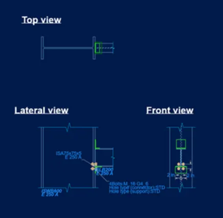
DXF Details:
- On the right hand side of the screen there is an option named as the DXF, just click on that option just as shown in the below given image:
- After selecting the DXF, it gives us the drafting view the Top View, Lateral View and the Front View of the connections just as shown in the below given image:
- Below is the given result in the STAAD Pro software: